NOMENCLATURE
- A 8
-
geometrical nozzle throat area
- A8c
-
ideal nozzle throat area given by engine control system
- A 8
-
equivalent nozzle throat area
- A8i
-
real isentropic throat area
- A 9
-
geometrical nozzle exit area
- Cc
-
mass flow coefficient of cooling air
- Cd
-
nozzle discharge coefficient
- Cf
-
nozzle thrust coefficient
- Fj
-
real nozzle thrust
-
 $L$
-
area of divergent flaps
-
${m_i}$
-
ideal isentropic gas flow through
${A_{8e}}$
-
${P_0}$
-
ambient pressure
-
$P_7^*$
-
total pressure at nozzle inlet
-
${P_9}$
-
static pressure at nozzle exit
-
$R$
-
gas constant
-
$T_4^*$
-
total temperature at turbine inlet
-
$T_7^*$
-
total temperature at nozzle inlet
-
${\beta _1}$
-
upper divergent flap angle
-
${\beta _2}$
-
lower divergent flap angle
-
${\delta _g}$
-
geometrical nozzle vector angle
-
${\delta _f}$
-
nozzle thrust vector angle
-
$\theta $
-
average divergent angle of the nozzle divergent flaps
-
$\pi $
-
nozzle pressure ratio
-
$\gamma $
-
specific heat ratio


Subscripts
-
$c$
-
parameters related to nozzle cooling air
-
$g$
-
parameters of the exhaust gas


1.0 INTRODUCTION
1.1 Background and related work
For modern multi-purpose operational aircraft, key characteristics, such as better manoevrability, survivability, and economic efficiency, are increasingly required. The purpose of thrust vectoring is to adjust the nozzle jet’s direction to deflect the jet thrust in pitch, yaw, and even reverse directions, and thus provide the aircraft with an extra steering moment. With this additional moment, aircraft have better performance in short take-off and landing, flight mobility, and post-stall manoeuvrability. Therefore, applying TV nozzles on existing non-thrust-vectored aircraft and aeroengines can greatly expand their flight control envelope and even reduce their infrared detectability. These outcomes improve the aircraft’s comprehensive operational capability(Reference Wilson, Adler and Bar-Yoseph1–Reference Benjamin3).
For a mature, deployed aeroengine, the operational characteristics are already deeply embodied, and the engine control system is optimised to ensure the engine components work in optimal operating states under most flight conditions. Under this circumstance, applying the TV nozzle on an existing aeroengine must retain the engine’s original operating states; these states must not be disturbed, even in the thrust-vectored states. Therefore, a relatively reliable TV nozzle configuration with the potential to retain the engine’s operational conditions is an ideal option(Reference Benjamin2,Reference Benjamin, Sherbaum and Lichtsinder4) .
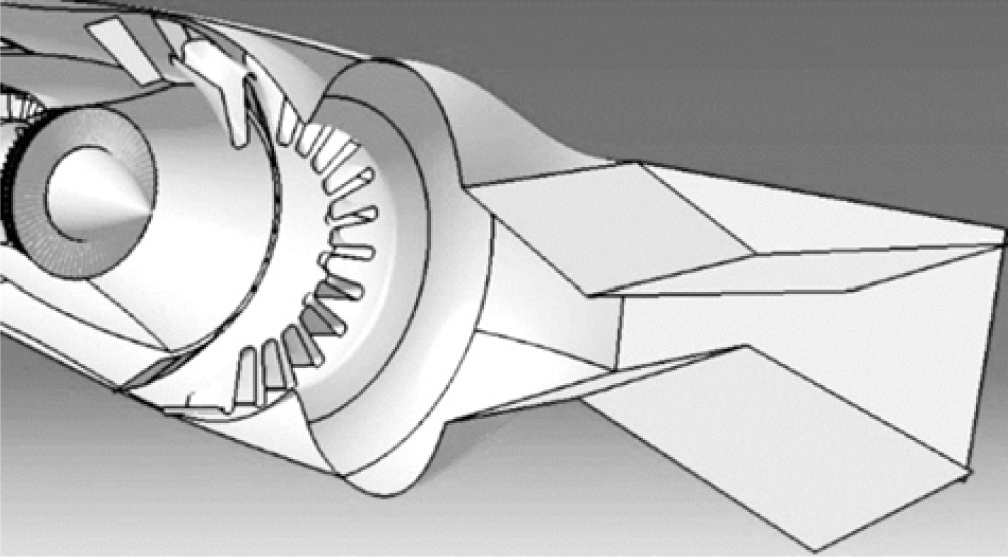
There are many kinds of TV nozzles that have been investigated, which can be grouped into two main categories: variable geometry, or mechanical, TV nozzles and fluid TV nozzles. The variable geometry TV nozzles can be further organised into jet vane, axisymmetric, spherical convergent flap, and 2-D TV nozzles(Reference Joslin and Miller5). The jet vane TV nozzle has a simple structure that has three or four jet vanes mounted behind the nozzle exit. By deflecting the jet vanes, the jet is vectored and the nozzle is supplied with a transverse aerodynamic force(Reference Berrier and Manson6). The jet vane TV nozzle is able to produce a substantial steering moment, but the thrust loss is unacceptable for aeroengines; thus, these are usually used in missiles(Reference Asbury and Capone7,Reference Orbekk8) . The axisymmetric TV nozzle is efficient in thrust. The inner flow channel is circular, and it can be vectored in both pitch and yaw directions. However, its configuration is not well suited for the integrated design with the afterbody of the airframe; the high-temperature core of the jet plume is relatively long, producing a disadvantageous infrared radiation source which limits it application(Reference Syed, Erhart and King9,Reference Chu, Der and Wun10) . The spherical convergent flap TV nozzle has a semi-spherical convergent section and a variable divergent section with a rectangular cross-section. It is able to produce vectored thrust in both pitch and yaw directions while maintaining low aerodynamic loss. Nonetheless, its configuration is complex and the spherical convergent section takes up a larger cross sectional area, making it inappropriate for transonic and supersonic aircraft(Reference Syed, Erhart and King9,Reference Cler, Mason and Guthrie11–Reference Mace, Smereczniak, Krekeler, Bowers, Maclean and Thayer13) . The 2-D TV nozzle, as shown in Fig. 1, has a thrust loss that is comparatively larger than axisymmetric TV nozzles and spherical convergent flap TV nozzles because its non-axisymmetric flow channel has a larger wet friction area. The 2-D TV nozzle is distinguished for being able to produce a substantial steering moment, control the nozzle and exit area independently with a relatively uncomplicated structure, and has a flat external configuration that is convenient for its integrated design with the airframe afterbody. Moreover, its rectangular exit enhances the mixing of the jet and the ambient atmosphere. This diminishes the high-temperature region of the jet plume and hence benefits its infrared stealthiness(Reference Parviz and Mcguirk14). These traits make the 2-D TV nozzle a promising option for aeroengine updates(Reference Joslin and Miller5,Reference Chu, Der and Wun10,Reference Mo, Xu, Gu and Fan15–Reference Hiley, Wallacet and Booz18) .
Sketch map of a 2-D TV nozzle.

The fluid TV nozzles can be further organised into dual throat (or confined jet), secondary gas injection (or shock), virtual aerodynamic surface skewing, and TV nozzles based on the Coanda effect(Reference Joslin and Miller5,Reference Chandra Sekar, Kushari, Mody and Uthup19,Reference Sellam, Zmijanovic, Leger and Chpoun20) . Among them, the dual throat TV nozzle is verified to produce vectored thrust by injecting secondary jet from near the front throat. This keeps the flow separation, i.e. the flow occupies one of the two recessed cavities. Thus, the flow channel is reshaped and the nozzle jet is deflected from the axis direction. However, the dual throat TV nozzles are reported to have deficiencies, such as thrust loss, instability in the thrust vectoring starting process, difficulty of secondary jet control, and non-linear responding characteristics(Reference Gu and Xu21–Reference Talda and Franke25). The secondary gas injection TV nozzle operates by injecting secondary gas into the over-expanded flow at the divergent section. This blocks the flow area and induces an oblique shock wave, so that gas passing through it and the jet thrust are deflected(Reference Li, Hirota, Ouchi and Saito26,Reference Li, Wang and Saito27) . Although a secondary gas injection TV nozzle produces considerable vectored thrust, it is beset with problems such as thrust loss due to the oblique shock and instability due to the interaction of shock and boundary layer separation. The independent control of the throat area and the thrust vector is less studied(Reference Deng, Kong and Kim28–Reference Asbury, Gunther and Hunter30). Studies of the virtual aerodynamic surface skewing TV nozzle and nozzles based on the Coanda effect, such as co-flow and counter-flow TV nozzles, are in the exploratory stages. The former uses secondary gas injected from the throat and the divergent section to realise nozzle throttling and jet deflection(Reference Williams and Vittal31). The latter injects or extracts gas beside the main flow. This creates an imbalanced pressure distribution in the divergent section which deflects the jet thrust(Reference Heo and Sung32–Reference Strykowski and Krothapalli35). In summary, fluid TV nozzles have numerous advantages, including a fixed geometry, and the potential to realise light-weight, high-thrust-efficiency, high manoeuvrability, high-speed flight, high-reliability, stealthiness, and highly integration with airframe. Therefore, they hold the promise to be an indispensable component for the next one or two generations of aircraft(Reference Chandra Sekar, Kushari, Mody and Uthup19). However, for modern aeroengines, the fluid TV nozzles consume a great amount of high-pressure secondary gas. This greatly influences the operating state of the engines and deteriorates the engine’s overall performance, ultimately offsetting some of the benefits of applying them(Reference Joslin and Miller5). Even for fluid TV nozzles that use no extra secondary gas(Reference Gu, Xu and Guo36,Reference Gu and Xu37) or newly proposed nozzles, studies of them are not mature at this time(Reference Cornelius and Lucius38–Reference Raman, Packiarajan, Papadopoulos, Weissman and Raghu40). In conclusion, for modern aeroengines, the variable geometry TV nozzles, especially the 2-D TV nozzle, offer a promising way to realise thrust vector capabilities.
Since the last three decades of 20th century, much research has been carried out on the 2-D TV nozzles; fluid dynamic analysis methods, such as experimental and computational fluid dynamics (CFD), have been used to simulate the nozzle flow fields and predict their performance(Reference Kashimura, Masuda, Miyazato and Matsuo41–Reference Hunter44). However, most of the research has focused on nozzle performance under certain working conditions. Little has been devoted to establish a set of nozzle performance characterisation methods that is conducive to aeroengine/TV nozzle integrated design in the whole flight envelope. In addition, little has been reported to deeply analyse the mechanism for the deterioration of the engine operating state and the decrease of the fan surge margin that are caused by the deflection of the TV nozzle, or to propose solutions to this problem(Reference Wilson, Adler and Bar-Yoseph1,Reference Wilson, Adler, Bal-Or, Sherbaum and Lichtsinder45–Reference Matesanz, Velazquez and Rodriguez47) . Furthermore, the indispensable nozzle cooling is also rarely considered. Accordingly, the aeroengine/TV nozzle matching mechanism, 2-D TV nozzle control schedule, and integrated aeroengine/TV nozzle modeling method that suits the requirements of promoting the overall engine performance to the greatest extent, lack systematic study. Under this condition, experiments and simulations of the nozzle may be restricted to the situation that performance data are measured in certain working conditions while the nozzle performance distribution in the whole flight envelope remains unknown, or that the resulting data do not fit the needs of engine overall performance design. For example, research has shown that an over-expanded jet is prone to suffer shock and separation at the end of the nozzle divergent section(Reference Xiao, Tsai, Papamoschou and Johnson48–Reference Munday, Gutmark, Liu and Kailasanath50), even incur an unbalanced jet force(Reference Johnson and Papamoschou51). Nevertheless, in some research, for not properly selecting the independent variables, the nozzle performance at the over-expanded conditions is tested, which is unwanted in practice. In other cases, for not properly controlling the nozzle throat area when deflecting, the decrease of the nozzle flow capacity incurs a conspicuous loss of the fan surge margin. Thus, a TV nozzle matching theory that is compatible to overall engine performance design is needed. Some researchers have made progress on this topic by establishing an integrated engine simulation model, designing nozzle control schedules, and implementing adaptive control(Reference Wilson, Adler and Bar-Yoseph1,Reference Benjamin2,Reference Gamble, Terrell and Defrancesco17,Reference Wilson, Adler, Bal-Or, Sherbaum and Lichtsinder45,Reference Hui-Min, Si-Qi and Han-Ping46,Reference Matesanz, Velazquez and Rodriguez52–Reference Lu, Zheng, Huang and Feng58) , but a comprehensive conclusion on cooled 2-D TV nozzle performance characterisation and integrated engine/nozzle control and modeling method is still lacking.
1.2 Research problem and methodology overview
This paper aims to address the gap identified above in the literature by solving this problem: how can the cooled 2-D TV nozzle performance in the whole flight envelope with minimal parameters be depicted and applied to aeroengine design to produce an optimal overall performance?
In order to achieve this goal, firstly, the geometrical features and operational mechanism of the nozzle are reviewed. Then, the matching mechanism of cooled TV nozzle with engine is analysed and the results are used to derive the guiding design principles for the cooled TV nozzle control.
Subsequently, the performance parameters of the cooled 2-D TV nozzle are defined and, based on the achievements obtained in the first section, a nozzle performance characterisation method is established. This method clarifies the mapping relation of the nozzle performance and the aerodynamic and the geometrical parameters.
Furthermore, a set of cooled 2-D TV nozzle control schedules with corresponding nozzle control and performance prediction algorithms is put forward, making the integrated aeroengine/TV nozzle control realisable in the engine control module.
Finally, in order to verify the feasibility of the control schedule, a 0-D component-level engine overall performance simulation model is reprogrammed so that it is able to calculate the nozzle control parameters and predict its performance. The testing results show that the integrated model is convergent in the whole flight envelope and is able to produce reliable nozzle control parameters. The comparative tests demonstrate the advantages of the nozzle control schedule put forward in this paper in maintaining the optimal engine working conditions over the basic approach currently available.
The detailed research steps and processes are presented in Section 2.
1.3 Contributions
The innovative contributions of this research are as follows:
First, on the component level, a succinct cooled 2-D TV nozzle performance characterisation method based on flow similarity theory is proposed. It portrays and predicts the nozzle performance in the whole flight envelope with only three independent variables, and may help to instruct future experimental and simulation work to better fit the needs of an engine’s overall performance design.
Second, on the engine/propeller matching level, the mechanisms of the problems that happen commonly in nozzle research, such as the fan surge margin loss and the thrust loss due to improper nozzle control, are analyzed and simulated in the paper. Based on these results, a set of control schedules and the corresponding implementation algorithms of cooled 2-D TV nozzle is put forward. These may help avoid these problems and produce maximum engine performance whenever nozzles deflect.
Moreover, on the engine/propeller modeling and simulation level, an integrated aeroengine/TV nozzle modeling method is put forward based on the former achievements. It helps to decouple these two parts, so that the effects of the cooled TV nozzle installed on the engine can be conveniently estimated. With this modeling method, engine operating state remains stable and exhaust gas expands completely whenever the nozzle deflects, and the proper nozzle control parameters can be calculated within a short amount of time.
These contributions can instruct the future experiments and CFD simulations of TV nozzles to better fit the needs of overall performance designs for engines.
1.4 Organisation of the article
The remainder of this article is organised as follows.
Section 2 presents the research methodology. The structure and cooling scheme of the 2-D TV nozzle are described, and the matching mechanism of it and the engine is analyzed in Section 3. Section 4 defines the nozzle performance parameters, and establishes a method for nozzle performance characterisation and prediction. In Section 5, the nozzle control schedules, together with the corresponding algorithms for nozzle control and performance prediction are put forward. And in Section 6, an integrated modeling method for aeroengines and cooled 2-D TV nozzle is proposed, and a programming application case of the method and the nozzle control schedules is presented. Conclusions are in Section 7.
2.0 RESEARCH METHODOLOGY
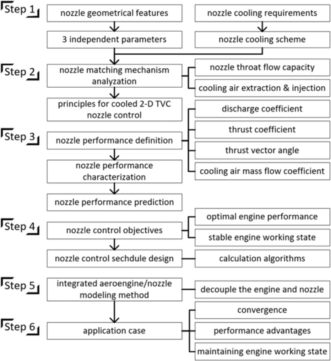
The research methodology utilised in this work to investigate the research question identified in the previous section consists of six main steps (refer to Fig. 2).
Flowchart of research methodology.

The first two steps guide the orientation of the following steps by ascertaining the structure and the cooling scheme of the nozzle and providing the guiding design principles for the nozzle control. Based on these foundations, the third and fourth steps establish the nozzle performance characterisation method and put forward the nozzle control schedules and the corresponding implementation algorithms, thus connect the research of nozzle with the needs of engine overall performance control. Based on the afore-proposed methods, the fifth and sixth steps establish and validate an integrated modeling method of the cooled 2-D TV nozzle and the engine. The validation consists of a demonstrative case to illustrate the application of the modeling method. In each of the main research steps, several processes are used; these steps are described below.
Step 1. Nozzle geometry and cooling scheme
In the first step, in order to facilitate the further study of matching mechanism of the cooled 2-D TV nozzle and the engine, the geometrical features and the working mechanism of the nozzle are firstly presented. Through a series of geometrical derivations, three independent parameters are ascertained to describe the nozzle geometry. Then, in view of the high nozzle wall temperature on engine afterburning conditions, cooling of the nozzle is added with a simplified scheme. This work acts as the foundation of the following research.
Step 2. Nozzle operational and matching mechanism
With the foundation stated afore, the matching problems of the nozzle and the engine, such as the fan surge margin loss caused by nozzle deflection, and the increase of the turbine inlet temperature caused by cooling air extraction, are analysed and simulated with an engine overall performance model. Based on the findings, design principles are put forward to guide the control of the cooled 2-D TV nozzle, which are adopted in the following steps. The details of step 1 and step 2 are available in Section 3.
Step 3. Nozzle performance characterisation and prediction
From the view of engine control and performance optimisation, the nozzle performance in the whole flight envelope is needed to be estimated with finite aerodynamic parameters. In order to simplify the estimation, the number of independent parameters used should be as few as possible. In this step, initially, four major performance parameters of cooled 2-D TV nozzle, which are discharge coefficient, thrust coefficient, thrust vector angle and cooling air mass flow coefficient are defined. Then, in order to simply the performance estimation process, based on flow similarity theory, a nozzle performance characterisation method that uses only three independent parameters is put forward. Based on that, the nozzle performance prediction method is established. This step is presented in Section 4.
Step 4. Design and implementation of nozzle control schedule
In the fourth step, the control schedule of the cooled 2-D TV nozzle is designed to ensure the aeroengine produces the optimum performance, and in the meantime, maintains a sufficient compressor surge margin. Corresponding to each engine operating state (e.g. idle, nozzle unchoked, nozzle choked, and afterburning), the nozzle control schedule is proposed. In order to properly control the nozzle geometry and predict the engine performance in an engine model or in practice, the algorithms to implement the control schedules are put forward. The details of this step are available in Section 5.
Step 5. Study on the integrated aeroengine/TV nozzle modeling method
In the fifth step, utilising the results of the prior steps, an integrated modeling method of the aeroengine and the cooled 2-D TV nozzle is proposed. This allows the performance of a low by-pass ratio (BPR) engine equipped with the nozzle to be simulated; the nozzle control parameters and its performance are obtainable.
Step 6. Validation of the integrated modeling method
To test the convergence and the feasibility of the proposed modeling method, a demonstrative application case is carried out in the sixth step. The testing results of the case show that the integrated model is convergent in the whole flight envelope and is able to produce reliable nozzle control parameters. And the comparative tests demonstrate the advantages of the proposed nozzle control schedule over the currently available basic approach with respect to maintaining better engine working conditions. The details about the fifth and the sixth step are presented in Section 6.
3.0 COOLED 2-D TV NOZZLE COOPERATING MECHANISM AND MATCHING WITH THE ENGINE
In this section, first the 2-D TV nozzle structure and geometrical characteristics are depicted and then the cooling scheme for the nozzle is stated. Then, the cooperating mechanism of the cooled 2-D TV nozzle with aeroengine is analysed, and the adverse consequences of their mismatching are illustrated. Based on these, some design principles for TV nozzle application and control are set forth to guide the following research.
3.1 Structure and geometrical parameters of a cooled 2-D TV nozzle
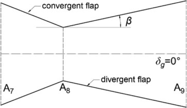
A 2-D TV nozzle has a relatively concise structure, of which the flow channel is mainly confined to a circle to rectangle transition section (not shown in the following figures), two convergent flaps, two divergent flaps, and two static side walls. The nozzle throat area can be adjusted when the convergent flaps rotate synchronously inward or outward, and the nozzle exit area and geometrical vector angle change if the divergent flaps rotate around the end of the convergent flaps.
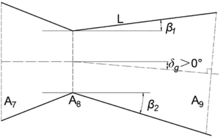
The structure and geometrical parameters are shown in Figs. 3 and 4.
As shown in Fig. 3, from a side view perspective, the two convergent flaps and the two divergent flaps confine the nozzle flow channel. The nozzle is a conjunct of a convergent section and a divergent section, and
 ${A_8}$
is the geometrical nozzle throat area.
Geometrical parameters of the 2-D TV nozzle (undeflected).

Geometrical parameters of the 2-D TV nozzle (downward deflected when
 $\beta $
s remain positive).

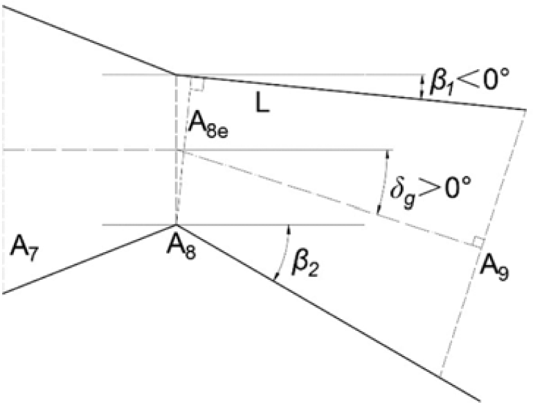
As shown in Fig. 4, in order to determine the geometry of the 2-D TV nozzle, in this paper,
 ${\beta _1}$
is defined as the upper divergent flap angle and
 ${\beta _2}$
is defined as the lower divergent flap angle; the angles are positive when the flaps turn outwards.
 ${\delta _g}$
represents the geometrical nozzle vector angle and is defined as follows:
 \begin{equation}{\delta _g} = {{\left( {{\beta _2} - {\beta _1}} \right)}/2}\end{equation}
Thus,
 ${\delta _g}$
is positive when
 ${\beta _1} < {\beta _2}$
, which means the nozzle turns downwards.
When the nozzle deflects, the nozzle’s exit position and area (
 ${A_9}$
) change as well. In this paper, for better describing the nozzle geometry and convenience in calculation, the nozzle exit is defined to be a specific surface. This surface is perpendicular to the average direction of the two divergent flaps, while meeting with the end of the one flap which turns more inward, as shown in Fig. 4.
It is admitted that
 ${A_9}$
under this definition does not thoroughly cover the whole nozzle channel (as shown in Fig. 4, the end part of the lower divergent flap is not covered by
 ${A_9}$
), and this may underestimate the gas expansion in the nozzle divergent section to some degree. However, the disadvantages of this definition can be offset in some aspects. First, as the gas flow at the nozzle exit is radially backward, choosing
 ${A_9}$
that is perpendicular to the average outflow direction can better represent the flow area. Second, this definition of
 ${A_9}$
can precisely describe the nozzle geometry. Finally, the deviation of the jet thrust prediction for non-isentropic effects and incomplete expansion is considered in the thrust coefficient.
Then,
 $\theta $
is defined as the average divergent angle as follows:
 \begin{equation}\theta = {\left( {{\beta _1} + {\beta _2}} \right)}/2\end{equation}
Furthermore,
 $L$
is defined to be the area of the divergent flaps, as shown in Fig. 4. For the reason that the 2-D TV nozzle is equal in width along the flow channel, the area ratios of the surface perpendicular to the page are also the length ratios presented in Figs. 3 and 4.
According to the former definitions, the geometrical equation between
 ${A_8}$
,
 ${A_9}$
,
 ${\delta _g}$
,
 $\theta $
and
 $L$
can be derived. When the nozzle deflects downwards, it can be written as follows:
 \begin{equation}{A_9}=2\sin (\theta )L + (\cos ({\delta _g}) - \tan (\theta )\sin ({\delta _g})){A_8}\end{equation}
or that between
 ${A_8}$
,
 ${A_9}$
,
 ${\beta _1}$
,
 ${\beta _2}$
, and
 $L$
is as follows:
 \begin{equation}{A_9}=2\sin \left(\frac{{{\beta _1} + {\beta _2}}}{2}\right)L + \frac{{\cos {\beta _2}}}{{\cos \left(\frac{{{\beta _1} + {\beta _2}}}{2}\right)}}{A_8}\end{equation}
When the nozzle deflects upwards (i.e.
 ${\delta _g}$
turns negative), the former equations are as follows:
 \begin{equation}{A_9}=2\sin (\theta )L + (\cos ({\delta _g}){\rm{ + }}\tan (\theta )\sin ({\delta _g})){A_8}\end{equation}
and
 \begin{equation}{A_9}=2\sin \left(\frac{{{\beta _1} + {\beta _2}}}{2}\right)L + \frac{{\cos {\beta _1}}}{{\cos \left(\frac{{{\beta _1} + {\beta _2}}}{2}\right)}}{A_8}\end{equation}
As shown in Fig. 5, the nozzle throat area is actually diminished when the nozzle deflects to an angle large enough such that one of the
 $\beta $
s turns negative. The equivalent nozzle throat area at this circumstance is named
 ${A_{8e}}$
. The relation between
 ${A_8}$
and
 ${A_{8e}}$
can be described as follows:
 \begin{equation}{A_{8e}} = \cos (\min (0,{\beta _1},{\beta _2})){A_8}\end{equation}
In this section, the structure and geometrical parameters of a 2-D TV nozzle are ascertained. Although actual 2-D TV nozzles are more complicated in structure, with these parameters the geometry of a 2-D TV nozzle can still be described in essence.
Geometrical parameters of the 2-D TV nozzle (downward deflected when
${\beta _1}$
is negative).

3.2 2-D TV nozzle cooling scheme
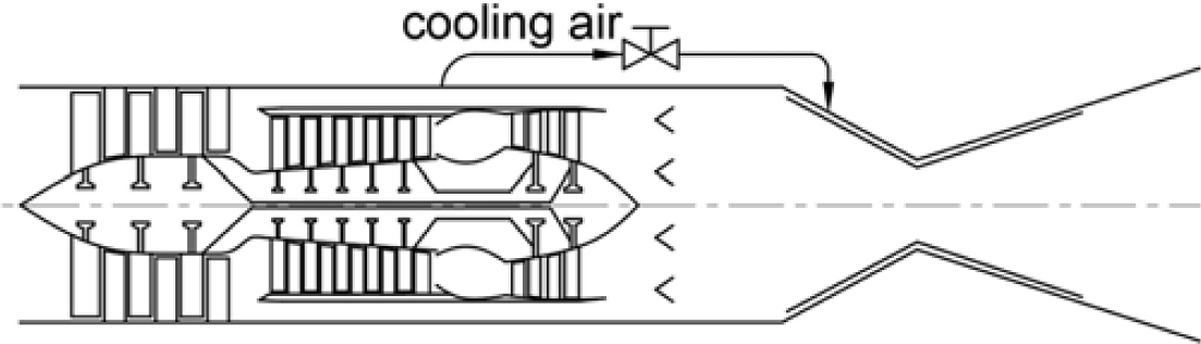
For military aircraft, afterburners are usually lit during taking offs and battles. In order to lower the nozzle surface temperature and prolong its life span, cooling measures are necessary. This paper aims to study the nozzle performance characterisation and control schedules from an overall perspective, and analyse the influence of a cooled nozzle on the primary engine; an over-detailed cooling scheme is inexpedient. Here, the nozzle cooling scheme is that the cooling holes are distributed on the nozzle side walls, convergent flaps, and front part of the divergent flaps; the cooling air is taken from one single resource.
As the total pressure of by-pass air flow in military aircraft engines is usually higher than that of the nozzle, especially when the afterburner is lit, and the temperature of the by-pass air is cool enough for the nozzle, this paper chooses the by-pass air as the cooling air resource.
Thanks to the advances of material technologies such as alloy design, casting, and thermal barrier coatings, the working temperature limits of aeroengine components are constantly increasing(Reference Clarke and Levi59,Reference Padture, Gell and Jordan60) . Considering the balance of costs and benefits, different components of aeroengines vary in material, technology, and consequently, working temperature limits. For nozzles, the working temperature limits of existing nozzle materials lies between 800
 $^{\circ}$
C to 1000
 $^{\circ}$
C(Reference Qin, Zhang, Bao, Zhou and Yu61,Reference Duan, Zhou, Qin, Bao and Yu62) . Usually, the total temperature of exhaust gas with the afterburner unlit is lower than this range, but the temperature rises rapidly and soon exceeds this range once the afterburner is lit. Under this situation, the primary cooling scheme in this paper is that when the afterburner is unlit, the cooling air is cut off; when the afterburner is lit, the nozzle cooling turns on at the same time.
In order to better achieve the cooling requirements, the rate of cooling air’s total pressure to that of the gas at the nozzle inlet section can be adjusted by the valve installed on the pipeline from the by-pass to the nozzle (as indicated in Fig. 6). For convenience in the nozzle control, this total pressure rate is fixed to a constant value (such as 1.05) in this paper. This premise is conducive to the studies presented in the latter sections.
2-D TV nozzle cooling layout.

The cooling scheme of the 2-D TV nozzle is stated in this section. It is worth mentioning that the probability in real circumstance that gas flows in the reverse direction (i.e. into the cooling hole) and discharges through the rear cooling holes when cooling air is cut off is not specifically modeled in this paper. Its influence is partially considered in the performance parameters of the nozzle.
3.3 Influence of cooled 2-D TV nozzle on the engine operating state and overall performance
The function of a nozzle includes discharging the mixed gas from the primary engine and adjusting the engine working conditions by restricting the gas flow with a proper nozzle flow area. Therefore, the flow area is the key nozzle parameter for engine operations. In addition, nozzle cooling also imposes an influence on the engine. These mechanisms are analysed in this section.
3.3.1 Influence of an adjustable nozzle area on the primary engine
The influence of a cooled 2-D TV nozzle on the engine can be analysed from two aspects, which are the nozzle flow area and nozzle cooling. The first factor is analysed in the following paragraphs.
When the nozzle is working in the choked state, according to the flow equation, the nozzle throat area
 ${A_{throat}}$
determines the mass flow of the gas through the nozzle
 ${m_g}$
as follows:
 \begin{equation}{m_g} = \sqrt {\frac{{{\gamma _g}}}{{{R_{\rm{g}}}}}{{\left(\frac{2}{{{\gamma _g}+1}}\right)}^{\frac{{{\gamma _g}+1}}{{{\gamma _{_g}} - 1}}}}} \frac{{P_{throat}^*{A_{throat}}}}{{\sqrt {T_{throat}^{\ast}} }}q(Ma)\end{equation}
where,
 $q(Ma)=1$
for the flow at the nozzle throat section is sonic,
 ${\gamma _g}$
is the specific heat ratio of the exhaust gas, and
 ${R_{\rm{g}}}$
is the gas constant of the exhaust gas.
Under this circumstance, reducing
 ${A_{throat}}$
leads to a decrease of the engine air flow. This interferes with the flux continuity of the engine and finally cause a deviation of the engine’s operating balance.
Fan surge margin variation with nozzle throat area decrease.

When the nozzle is working in the unchoked state, the Mach numbers at the nozzle throat section and the exit do not reach 1, and the static pressure at the nozzle exit
 ${P_9}$
equals the ambient pressure
 ${P_0}$
. Under this circumstance, reducing
 ${A_9}$
improves the gas expansion. This leads to an increase of the total pressure at the nozzle inlet
 $P_7^*$
; hence, this influences the engine operating state.
For twin-spool aeroengines that have a by-pass located behind the fan, the increase of
 $P_7^*$
(or the total pressure at the mixer outlet
 $P_6^*$
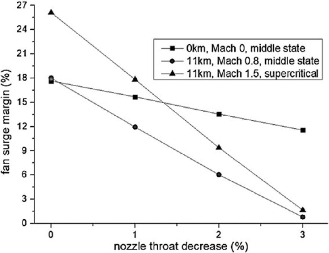
) caused by the diminution of the nozzle throat area influences the engine operating state from two aspects. The first is that the increase of the total pressure behind the low pressure turbine (LPT) causes its pressure ratio to decrease, and the low pressure rotor (LPR) decelerates because the LPT is not producing enough power. At this moment, the engine control system, usually conforming to the control schedule of maintaining the LPR speed, increases the burner fuel supply. As a result, the LPR speed remains stable while the high pressure rotor (HPR) works at a higher speed and the high pressure compressor (HPC) draws in more air. Consequently, the fan operating point on the characteristic map moves further from the surge boundary along the constant-speed line. From the second aspect, the increased back pressure of the by-pass blocks the air flow of the fan, under the condition that the LPR speed remains unchanged. As a result, the fan operating point moves toward the surge boundary, which may improve the engine performance to some small extent, but also impose a threat on the aircraft safety. The consequent variation of the fan operating point relates to these two aspects and mainly depends on the BPR. For engines that have relatively small BPRs, the first factor dominates when the nozzle throat diminishes, while for engines that have larger BPRs, the diminution of the nozzle throat causes the fan operating line to move nearer to the surge boundary(Reference Hamed and Vogiatzis49). In this paper, based on a 0-D component-level simulation model of a mixed-exhaust engine with a designed BPR that is approximately 0.7, the fan surge margin variation with nozzle throat diminution under several typical flight conditions are estimated (Fig. 7). The results show that reduction of the nozzle throat area deteriorates the fan operating state. In summary, properly controlling the nozzle throat area is the key to maintaining the engine working state.
According to the previous section, deflecting the 2-D TV nozzle causes the skewing of the nozzle throat and the diminution of its area from
 ${A_8}$
to
 ${A_{8e}}$
if one of the divergent flap angles turns negative. For this reason, in order to maintain the engine working condition, ensuring the nozzle throat area remains constant when the nozzle deflects is a key consideration. Because the influence of non-isentropic factors and the cooling air, the real nozzle throat flow area is always less than
 ${A_{8e}}$
; thus, the discharge coefficient
 ${C_d}$
requires consideration in the nozzle control process.
3.3.2 Influence of nozzle cooling on the engine performance
According to the nozzle cooling scheme in this paper, cooling air is extracted from the engine by-pass and injected through the cooling holes on the wall of nozzle, both before and after the geometrical nozzle throat section. This cooling scheme influences the primary engine from four main aspects; each of these is discussed below.
First, the impact of air extraction from the by-pass is analogous to opening an air bleed valve there. The by-pass air flux increases and part of the core engine flux is apportioned to the by-pass. As a consequence, the whole engine flux increases and the fan operating line moves further from the surge boundary.
Second, some of the compressed by-pass air is extracted without being heated in the burner and afterburner nor expanding in the turbine. In order to maintain the LPR speed, the total temperature at the high pressure turbine inlet
 $T_4^*$
has to increase.
Third, part of the cooling air is injected into the nozzle before the nozzle throat and it occupies some of the nozzle flow area; as a result, the flow area for the gas is reduced. Its influence is analogous to narrowing
 ${A_8}$
for the nozzle without cooling, and similarly impacts the engine’s operating state.
Finally, cooling imposes a direct effect on the 2-D TV nozzle. Using the cooling air reduces the nozzle wall temperature; this benefits the nozzle life-span and improves the aircraft infrared stealthiness. In addition, the injection of cooling air at the nozzle divergent section can serve as a secondary jet and influence the nozzle flow field in the nozzle vectoring state. This impacts the nozzle thrust coefficient and the nozzle thrust vector angle.
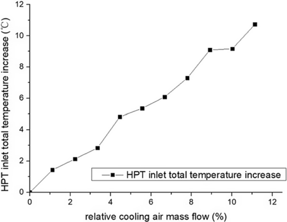
According to the analyses above, with a properly controlled nozzle flow area, the influence of nozzle cooling on the primary engine’s operating state can be equivalent to by-pass air bleeding. Using a 0-D aeroengine overall performance simulation model, the variation of the engine’s operating point caused by cooling air extraction can be tested. According to the tests, under the flight conditions of 11km, Mach number equal to 0.8, and the afterburner being lit, increasing the cooling air mass flow extracted from the by-pass,
 $T_4^*$
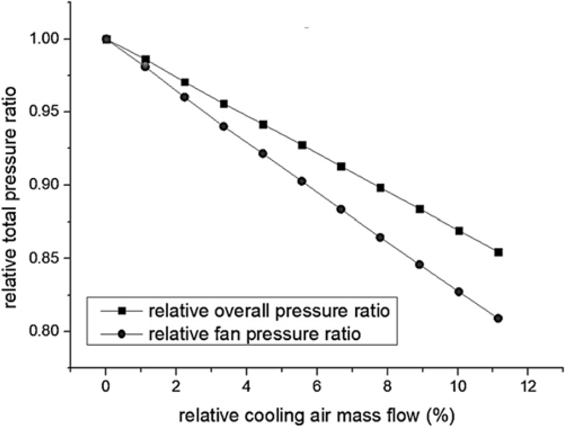
increases approximately 0.94K per hundredth of total air flow extracted (Fig. 8), and the overall total pressure ratio decreases approximately 1.31% (1.72% for the fan) per hundredth of the total air flow extracted (Fig. 9). These results illustrate that the overuse of cooling air deteriorates the engine thermal cycle.
Increase of
 $T_4^*$
with cooling air extraction.

Decrease of fan/overall total pressure ratio with cooling air extraction.

3.3.3 Design principles for a cooled 2-D TV nozzle control schedule
The former discussion analyses the influence of using the cooled 2-D TV nozzle on the engine’s operation and overall performance. Now, some conclusions can be drawn which reveal four principles for the cooled 2-D TV nozzle control schedule design.
First, the nozzle flow area (
 ${A_{8e}}$
when the nozzle is in the choked state, or
 ${A_9}$
in the unchoked state) is the critical factor to maintain the working conditions of the primary engine, and the nozzle discharge coefficient is needed to predict the real flow area.
Second, although the injection of cooling air benefits the nozzle structure, over extracting by-pass air causes the deterioration of the engine thermal cycle. Thus, it is better to use less nozzle cooling air once the cooling objective is achieved.
Third, as the cooling air imposes additional influence on the nozzle performance, it is necessary to introduce factors of the cooling air in nozzle performance prediction.
Finally, when extracting and using cooling air, if the nozzle throat area is properly controlled such that the cooling air injected before the nozzle throat section discharges without either reducing or expanding the gas flow area, the consequences of cooling air usage can be equivalent to that of air bleeding at the by-pass.
Here, the principles that require attention in the control of 2-D TV nozzles have been presented. In the following sections, these are adopted in the design of the nozzle control schedules.
4.0 COOLED 2-D TV NOZZLE PERFORMANCE CHARACTERISATION AND PREDICTION
Based on the 2-D TV nozzle geometry characteristics, the nozzle cooling scheme, and the nozzle control design principles stated above, this section mainly discusses the parameters that represent nozzle performance. These parameters are the nozzle discharge coefficient, thrust coefficient, thrust vector angle, and cooling air mass flow coefficient. The definition, calculation, characterisation and prediction of these parameters are presented below.
4.1 Definitions of cooled 2-D TV nozzle performance parameters
4.1.1 Discharge coefficient
The nozzle discharge coefficient is used to represent how the non-isentropic factors and cooling air diminish the gas flow area at the nozzle throat. It is used to maintain engine working conditions by giving a proper nozzle geometry.
For cooling air is used only when the afterburner is lit, the discharge coefficient definition differs under two conditions: with and without cooling.
The discharge coefficient without cooling is defined by the following equation:
 \begin{equation}C_{d}=m_{g}/m_{i}\end{equation}
where,
 ${m_g}$
is the real mass flow of the exhaust gas, and
 ${m_i}$
is the ideal isentropic gas flow through the equivalent nozzle throat area
 ${A_{8e}}$
in the pneumatic state at the nozzle inlet. and the value of
 ${m_i}$
can be calculated by the following equation when the nozzle is in the choked state:
 \begin{equation}{m_g} = K{A_{8i}}{P_7^{*}}/{\sqrt{T_7^{\ast}} }\end{equation}
where,
 \begin{equation}K = \sqrt {\frac{{{\gamma _g}}}{{{R_g}}}{{\left( {\frac{2}{{{\gamma _g}+1}}} \right)}^{\frac{{{\gamma _g}+1}}{{{\gamma _g} - 1}}}}}\end{equation}
On the other hand,
 ${m_g}$
can be considered as the ideal isentropic gas flow through the real isentropic throat area
 ${A_{8i}}$
. This is presented by the following equation:
 \begin{equation}{m_g} = K{A_{8i}}{P_7^{*}}/{\sqrt {T_7^{\ast}} }\end{equation}
From this view, the discharge coefficient without cooling can be defined in another form as follows:
 \begin{equation}{C_d} = {{{A_{8i}}}/A_{8e}}\end{equation}
With this definition,
 ${C_d}$
can be used to produce the proper nozzle geometry.
When the afterburner is lit, the discharge coefficient with cooling can be defined by the following equation:
 \begin{equation}{C_{dc}} = \frac{{{m_g}}}{{K{A_{8e}}}{P_7^*}/{\sqrt {T_7^{\ast}} }}\end{equation}
In this equation, the denominator is the ideal isentropic gas flow through
 ${A_{8e}}$
in the pneumatic state at the nozzle inlet. It is worth noting that the form of the definition of the discharge coefficient with cooling is equal to that without cooling, so
 ${C_{dc}}$
can be used to give the proper geometry as
 ${C_d}$
. Because the cooling air injected in the front of the equivalent nozzle throat occupies part of the flow area,
 ${C_{dc}}$
is correspondingly smaller than
 ${C_d}$
on average.
4.1.2 Thrust coefficient
The nozzle thrust coefficient is used to measure the influence of the non-isentropic factors, cooling air, incomplete gas expansion, and non-axial exit gas velocity component on the jet thrust. With thrust coefficient, the nozzle thrust can be predicted.
Corresponding to the cooling air condition, the thrust coefficient differs when afterburner is lit or not.
The thrust coefficient without cooling is defined by the following equation:
 \begin{equation}C_{f}=F_{j}/F_{i}\end{equation}
where,
 ${F_j}$
is the real thrust acting on the nozzle, and
 $F$
is the ideal thrust when the gas isentropically fully expands. and the value of
 $F$
can be calculated as follows:
 \begin{equation}F_{i} =m_{g} \sqrt{\frac{2\gamma _{g} }{\gamma _{g} -1} \left(1-\left(\frac{P_{0} }{P_{7}^{\ast} } \right)^{\frac{\gamma _{g} -1}{\gamma _{g} } } \right)R_{g} T_{7}^{\ast} }\end{equation}
When the afterburner is lit, the thrust coefficient with cooling can be defined by the following equation:
 \begin{equation}C_{fc} =\frac{F_{j} }{m_{g} \sqrt{\frac{2\gamma _{g} }{\gamma _{g} -1} \left(1-\left(\frac{P_{0} }{P_{7}^{\ast} } \right)^{\frac{\gamma _{g} -1}{\gamma _{g} } } \right)R_{g} T_{7}^{\ast} } + m_{{\rm c}} \sqrt{\frac{2\gamma _{c} }{\gamma _{c} -1} (1-(\frac{P_{0} }{P_{c}^{\ast} } )^{\frac{\gamma _{c} -1}{\gamma _{c} } } )R_{c} T_{c}^{\ast} } }\end{equation}
where, the symbols with subscripts c are the parameters of the cooling air. The denominator of this equation is the thrust produced by the gas and the cooling air together on the condition that they isentropically fully expand. The cooling air mass flow
 ${m_{\rm{c}}}$
is subject to the same factors with the thrust coefficient under the cooling scheme where the total pressure rate of the cooling air and gas is constant. As a result, the only independent parameter of the second component in the denominator is the total temperature of the cooling air
 $T_c^*$
. As
 $T_c^*$
varies within a limited range and the thrust produced by the cooling air is relatively negligible to that of gas, this paper suggests the following simplified definition of the thrust coefficient reflects the degree of the mixed air expansion in essence:
 \begin{equation}C_{fc} =\frac{F_{j} }{m_{g} \sqrt{\frac{2\gamma _{g} }{\gamma _{g} -1} \left(1-\left(\frac{P_{0} }{P_{7}^{\ast} } \right)^{\frac{\gamma _{g} -1}{\gamma _{g} } } \right)R_{g} T_{7}^{\ast} } }\end{equation}
By this method, the form of the thrust coefficient definition is the same whether the afterburner is lit or not, which simplifies the prediction of nozzle thrust.
It is worth noting that because of the definition method, the thrust coefficient with cooling can exceed 1 under some circumstances, while the thrust coefficient without cooling is consistently less than 1.
4.1.3 Thrust vector angle
The nozzle thrust vector angle is used to predict the deflection of the nozzle thrust and, in turn, the axial thrust and pitching moment. As with the former performance parameters, the thrust vector angle needs to be defined for two cases: without and with cooling.
The thrust vector angle without cooling is defined as follows:
 \begin{equation}{\delta _f} = \arctan ({{{F_{jz}}}/{{F_{jx}}}})\end{equation}
where,
 ${F_{jz}}$
is the nozzle thrust in the vertical direction and
 ${F_{jx}}$
is the nozzle thrust in the axial direction. This paper defines
 ${F_{jz}}$
to be positive when the jet thrust is upward and negative otherwise. Therefore, the thrust vector angle is positive when the jet turns downwards, as with the geometrical nozzle vector angle.
The thrust vector angle with cooling can be defined in the same way:
 \begin{equation}{\delta _{fc}} = \arctan ({{{F_{jzc}}}/{{F_{jxc}}}})\end{equation}
4.1.4 Mass flow coefficient of cooling air
According to the cooling scheme in this paper, the cooling air is extracted from the engine by-pass and injected into the nozzle channel with a constant total pressure ratio to the gas. The mass flow coefficient of the cooling air is defined to be the corrected mass flow ratio of the cooling air to gas:
 \begin{equation}C_{c} ={m_{c} \sqrt{T_{c}^{\ast} } P_{g}^{\ast} \mathord{\left/ {\vphantom {m_{c} \sqrt{T_{c}^{\ast} } P_{g}^{\ast} \left(m_{g} \sqrt{T_{g}^{\ast} } P_{c}^{\ast} \right)}} \right. } \left(m_{g} \sqrt{T_{g}^{\ast} } P_{c}^{\ast} \right)}\end{equation}
As analysed in the former sections, the cooling air injected in the front of the critical section occupies some flow area, and the air injected downstream influences the gas expansion. Thus, dividing the cooling air mass flow into these two parts is necessary in a detailed nozzle flow study. The two parts of the cooling air mass flow injected into the nozzle are as follows:
 \begin{equation}{m_c} = {m_{c1}} + {m_{c2}}\end{equation}
where,
 ${m_{c1}}$
is the cooling air mass flow injected at the front of the critical section, and
 ${m_{c2}}$
is injected downstream of the critical section.
The mass flow coefficient of the cooling air injected at the front of the critical section is defined as follows:
 \begin{equation}C_{c1}=m_{c1}/m_{c}\end{equation}
At this point in the paper, the four major nozzle performance parameters have been defined. With these parameters, the discussion proceeds to the characterisation and prediction of the cooled 2-D TV nozzle performance. A set of nozzle control schedules with algorithms are put forward below.
4.2 Cooled 2-D TV nozzle performance characterisation
The definitions of cooled 2-D TV nozzle performance have been given in the previous section, and with these definitions the nozzle performance under certain working conditions can be obtained. While in the process of modeling and assessing the engine’s overall performance, nozzle performance prediction in the whole flight envelop is required. Therefore, in order to draw the nozzle performance distribution with the finite experimental cases, this section establishes the function of nozzle performance with the relevant predominant factors, i.e. the characterisation of the nozzle performance.
To establish the characterisation of cooled 2-D TV nozzle performance, several predominant parameters of nozzle flow need to be chosen first. According to the first section, for a certain 2-D TV nozzle without scaling, three independent parameters determine the similarity of the nozzle geometry:
 ${A_8}$
,
 ${\delta _g}$
, and
 $\theta $
. In addition, other parameters are needed to guarantee the similarity of nozzle flow and dynamics.
For a macro-scale, relatively high-temperature mixing flow phenomenon without a chemical reaction, such as the flow in a cooled 2-D TV nozzle, the criteria to guarantee the flow similarity mainly include the Reynold number, Mach number distribution, and parameters that effect the mixing of the cooling air. In a typical airplane’s flight envelope, the Reynold number at the nozzle is high enough such that the nozzle flow is fully turbulent, so the Reynold number criterion is not strictly necessary. Therefore, only the distributions of the Mach number and the cooling air injection are the criteria that determine flow similarity. According to relevant research, the total temperature of the gas has little influence on the nozzle flow field(Reference Kim, Kim, Choi, Park and Kwon63). Therefore, on the condition that the nozzle geometry and the cooling scheme are given, the main parameter that determines the Mach number distribution is the nozzle pressure ratio
 $\pi $
, which is defined as follows:
 \begin{equation}\pi ={P_{7}^{\ast} \mathord{\left/ {\vphantom {P_{7}^{\ast} P_{0} }} \right. } P_{0} }\end{equation}
On the condition that the nozzle geometry and
 $\pi $
are settled, the distribution of the cooling air can essentially be described by two coefficients:
 ${C_{\rm{c}}}$
and
 ${C_{{\rm{c1}}}}$
. Consequently, the characterisation of the cooled 2-D TV nozzle performance can be written in the following form:
 \begin{equation}{C_{xc}} = {f_{{C_{xc}}}}({A_8},{\delta _g},\theta ,\pi ,{C_{\rm{c}}},{C_{{\rm{c1}}}})\end{equation}
where,
 ${C_{xc}}$
can be the nozzle discharge coefficient, thrust coefficient, or thrust vector angle on the condition that the afterburner is lit.
Correspondingly, the nozzle performance characterisation with the afterburner unlit can be written as follows:
 \begin{equation}{C_x} = {f_{{C_x}}}({A_8},{\delta _g},\theta ,\pi )\end{equation}
However, the functions listed above contain a large number of parameters, and a simplified form is sought. Considering the factors that influence the cooling air distribution, the cooling air mass flow through each cooling hole on the nozzle wall is dependent on the total pressure of cooling air and the static pressure at the nozzle outlet. It can be found that under the cooling scheme given by this paper, which keeps a constant total pressure ratio of cooling air and gas, the cooling air distribution is principally dependent on the static pressure distribution in the nozzle. The nozzle static pressure distribution depends on the nozzle geometry and
 $\pi $
apart from the cooling air influences. Therefore, the cooling air mass flow coefficients can be characterised as follows:
 \begin{equation}({C_{\rm{c}}},{C_{{\rm{c1}}}}) = {f_{{C_c}}}({A_8},{\delta _g},\theta ,\pi )\end{equation}
With this equation, the last two variables in Equation (25) is dependent on the front four variables. Thus, Equation (25) can be written as follows:
 \begin{equation}{C_{xc}} = {f_{{C_{xc}}}}({A_8},{\delta _g},\theta ,\pi )\end{equation}
Furthermore, the nozzle performance characterisation can be simplified. According to gas dynamics principles, the nozzle produces the greatest thrust when the gas is fully expanded. The gas expansion depends on
 $\pi $
and the area ratio of the divergent section
 ${{{A_{{\rm{exit}}}}}} $
/
 $ {{A_{throat}}}$
for a convergent-divergent nozzle. For the existence of three-dimensional effects and cooling air mixing, it is impractical to measure the real areas of the nozzle exit and the throat. Therefore, according to the fundamental principle of gas dynamics, this paper suggests using
 ${A_{8i}}$
to represent the nozzle throat area, and
 ${A_9}$
to represent the nozzle exit area. In order to achieve better nozzle gas expansion,
 ${{{A_9}}} $
/
 $ {{A_{8i}}}$
needs to fully depend on
 $\pi $
as follows:
 \begin{equation}A_{9}/A_{8i}=f_{A_9/A_{8i}}(\pi)\end{equation}
Under the hypothesis that the cooling air is negligible and the nozzle flow is one-dimensional and ideally isentropic, this function is written as follows:
 \begin{equation}f_{A_9/A_{8i}}(\pi) =\left(\frac{2}{{{\gamma _{\rm{g}}}+1}}\right)^{\frac{{{\gamma _{\rm{g}}}+1}}{{2({\gamma _{\rm{g}}} - 1)}}}\left(\frac{2}{{{\gamma _{\rm{g}}} - 1}}\left({\pi ^{\frac{{{\gamma _{\rm{g}}} - 1}}{{{\gamma _{\rm{g}}}}}}} - 1\right)\right)^{ - \frac{1}{2}}{\pi ^{\frac{{{\gamma _{\rm{g}}}+1}}{{2{\gamma _{\rm{g}}}}}}}\end{equation}
In practical application, considering the influence of the cooling air injection, the non-isentropic effects, and the requirement to maintain the airplane rear fuselage profile, the function of and
 $\pi $
certainly needs to be amended; however, the function written above is still persuasive in describing the constraint between
 ${{{A_9}} }$
/
 $ {{{A_{8i}}}}$
and
 $\pi $
.
With Equations (1–3, 5, 7, 13 and 30), one more variable
 $\theta $
in Equation (25) is dependent. So, only three variables in the nozzle performance characterisation are independent, which are
 ${A_8}$
,
 ${\delta _g}$
, and
 $\pi $
. The nozzle performance can be written as follows:
 \begin{equation}{C_{xc}} = {f_{{C_{xc}}}}({A_8},{\delta _g},\pi )\end{equation}
where,
 ${C_{xc}}$
can be
 ${C_{dc}}$
,
 ${C_{fc}}$
, or
 ${\delta _{fc}}$
.
When afterburner is unlit, the nozzle performance can be written as follows:
 \begin{equation}{C_x} = {f_{{C_x}}}({A_8},{\delta _g},\pi )\end{equation}
where,
 ${C_x}$
can be
 ${C_d}$
,
 ${C_f}$
, or
 ${\delta _f}$
.
The mass flow coefficients of cooling air can be written as follows:
 \begin{equation}({C_{\rm{c}}},{C_{{\rm{c1}}}}) = {f_{{C_c}}}({A_8},{\delta _g},\pi )\end{equation}
At this point in the paper, the nozzle performance characterisation has been established, and the three independent variables, which are also the nozzle flow similarity criteria, have been determined. With this characterisation, the nozzle performance prediction and the nozzle controlling process can be realised.
4.3 Prediction of cooled 2-D TV nozzle performance
The former section has established the nozzle performance characterisation with three independent variables, upon which the nozzle performance can be predicted.
Assuming that by simulation and experiments, the cooled 2-D TV nozzle performance parameters (
 ${C_{dc}}$
,
 ${C_{fc}}$
,
 ${\delta _{fc}}$
,
 ${C_{\rm{c}}}$
,
 ${C_d}$
,
 ${C_f}$
and
 ${\delta _f}$
) under varying working conditions (
 ${A_8}$
,
 ${\delta _g}$
and
 $\pi $
) are available. Then, this paper suggests using three-dimensional linear interpolation to predict the nozzle performance in a wide flight envelope, which can be built via the following three steps:
First, calculate the varying range of
 ${A_8}$
,
 ${\delta _g}$
and
 $\pi $
in the whole engine flight envelope.
Second, establish a three-dimensional coordinate system with the coordinate axes being
 ${A_8}$
,
 ${\delta _g}$
and
 $\pi $
, and divide the axes into several sections that cover the engine flight envelope with (on the whole) evenly separated nodes. For practical application, however, the nodes near the predominant flight conditions are separated more densely.
Third, the cubes in the coordinate system constrained by the neighboring nodes on each axis constitute the three-dimensional linear interpolation regions.
Finally, when any nozzle performance
 ${C_x}$
under certain working conditions (
 ${A_8}$
,
 ${\delta _g}$
and
 $\pi $
) is needed, it can be predicted in the interpolating region that contains the working point.
In this section, the definitions of each performance parameter are ascertained, and characterisation for each of them is established. With this work, the nozzle performance predicting method is put forward. It is worth noting that the concise form of the nozzle performance characterisation and prediction is based on the conditions that the area ratio of the nozzle divergent section depends on
 $\pi $
, and the total pressure ratio of the cooling air and nozzle gas is fixed. These conditions need to be realised in the nozzle control schedule design, which is studied in the next section.
5.0 COOLED 2-D TV NOZZLE CONTROL SCHEDULE AND NOZZLE CONTROL/PERFORMANCE PREDICTION ALGORITHMS
In the former sections, the definition, characterisation, and prediction of the cooled 2-D TV nozzle performance parameters are established, and the principles in the design of the nozzle control schedule are listed. In this section, based on the former achievements, the cooled 2-D TV nozzle control schedule and algorithms of nozzle control and performance prediction are discussed. These support nozzle modeling and application in practice.
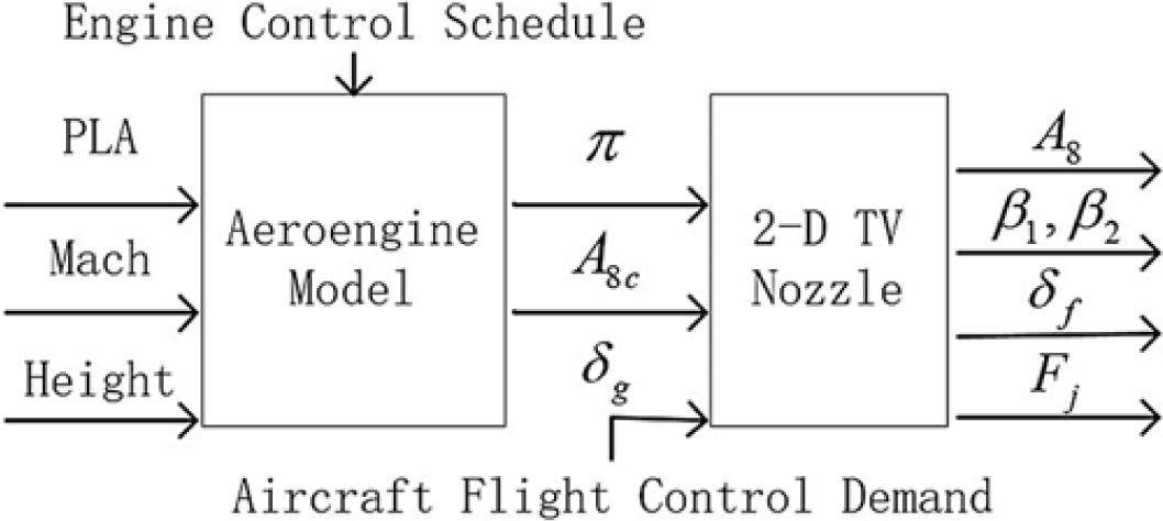
In the design of a nozzle control schedule, the input parameters are the ideal nozzle throat area for gas
 ${A_{8c}}$
given by the engine control schedule,
 $\pi $
, and
 ${\delta _g}$
. The output parameters are
 ${A_8}$
,
 ${\beta _1}$
, and
 ${\beta _2}$
, which can be conveniently used to adjust the nozzle geometry.
5.1 Objectives of nozzle control schedule design
The main function of the TV nozzle is to adjust the engine working state and produce the vectored jet thrust. Thus, the objectives of the nozzle control schedule design are maintaining the optimal engine working state and producing enough thrust under any condition, whether the nozzle deflects or not.
Corresponding to the cooling scheme in this paper, the nozzle control schedule needs to be designed to consider the cases when the afterburner is lit or not.
When the afterburner is unlit, in order to maintain the engine working state,
 ${A_{8i}}$
needs to be kept equal to
 ${A_{8c}}$
, and to produce enough thrust, the correspondence of
 ${{{A_9}} \mathord{\left/{{A_{8i}}}\right.}}$
and
 $\pi $
needs to be in accordance with Equation (29). As
 ${C_{\rm{d}}}$
varies with the nozzle geometry and
 $\pi $
, the nozzle control subsystem has to update the nozzle control parameters and predict the nozzle performance under each nozzle working condition.
When the afterburner is lit, the changing cooling air mass flow influences the engine’s working state, and in turn affects the nozzle’s working condition. In this case, the nozzle control becomes more complicated and has to be coupled with the engine overall performance simulation program; these are stated in the following sections.
5.2 Cooled 2-D TV nozzle control schedule and nozzle control/performance prediction algorithms
Based on the former discussion, in this section, a set of control schedule for the cooled 2-D TV nozzle under each of the four engine’s operating states is put forward. In addition, detailed implementations of the algorithms are presented.
5.2.1 Startup/idle state
When the engine operates in the startup or idle state, the major objective of the nozzle control is discharging gas. Under this condition, the nozzle control scheme is fixing the nozzle throat at the largest limit. The divergent flaps stretch straight backwards, so that the value of
 $\pi $
is approximately 1 and the turbines work under a high enough pressure ratio.
5.2.2 Nozzle unchoked state
When the nozzle works in the unchoked state, the nozzle flow is subsonic and the engine thrust is relatively small. Under this condition, vectored thrust is unnecessary, which means
 ${\delta _g}$
,
 ${\beta _1}$
, and
 ${\beta _2}$
are equal to zero degrees, so the only control parameter left is
 ${A_8}$
. In order to maintain the primary engine operating state, the nozzle control scheme keeps
 ${A_{8i}}$
equal to
 ${A_{8c}}$
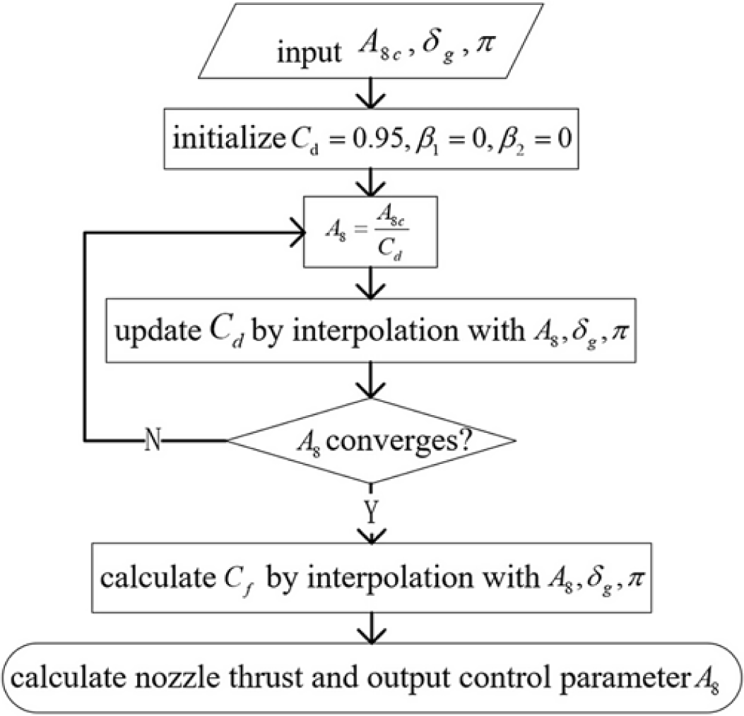
, and the divergent flaps stretch straight backwards. The detailed nozzle control and prediction algorithm is presented in Fig. 10.
Nozzle control and prediction algorithm in the unchoked state.

When the engine operating state simulation completes, the inlet parameters (i.e.
 ${A_{8c}}$
,
 $\pi $
) are all obtained(Reference Sanghi, Lakshmanan and Rajasekaran64). Through this algorithm, a proper value for the control parameter
 ${A_{8c}}$
can be obtained, and the engine’s overall performance can be predicted.
5.2.3 Nozzle choked state with afterburner unlit
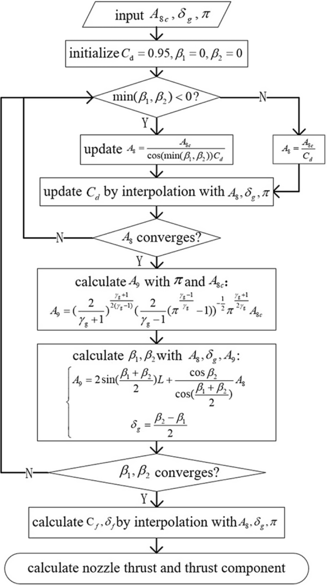
When the nozzle works in the choked state and the afterburner is unlit, the flow in nozzle divergent section is hypersonic and the nozzle thrust is large enough such that the vectored thrust is available. Under this condition, the nozzle control scheme adjusts the nozzle geometry with the proper control parameters to meet the control requirements. These requirements are that
 ${A_{8i}}$
is equal to
 ${A_{8c}}$
,
 ${\delta _g}$
is achieved, and the function between
 ${{{A_9}} \mathord{\left/{{A_{8i}}}\right.}}$
and
 $\pi $
is maintained. The detailed nozzle control and prediction algorithm is presented in Fig. 11.
Nozzle control and prediction algorithm in the unchoked state with the afterburner unlit.

After these iterative processes, exact values of the nozzle control parameters (i.e.
 ${A_8}$
,
 ${\beta _1}$
, and
 ${\beta _2}$
) are obtainable to guarantee the nozzle working conditions, and the nozzle thrust in the axial and vertical directions can be calculated.
5.2.3 Nozzle choked state with afterburner lit
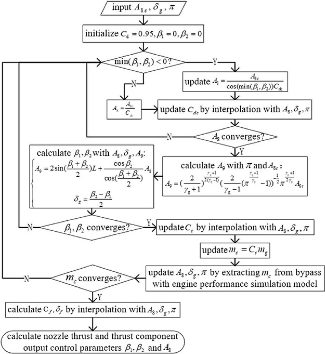
When the afterburner is lit, the nozzle thrust boosts rapidly, and cooling air is applied at the same time. Under this circumstance, producing the nozzle control parameters is more complicated, as the engine’s overall simulation model is invoked during the calculation. The detailed nozzle control and prediction algorithm is shown in Fig. 12.
Nozzle control and prediction algorithm in the choked state with the afterburner lit.

With this algorithm, the nozzle can be properly controlled with exact control parameters,
 ${A_8}$
,
 ${\beta _1}$
, and
 ${\beta _2}$
; in addition, the engine performance can be predicted as well.
The nozzle control and performance prediction algorithms established in this section can be applied in the integrated modeling of the engine and the cooled 2-D TV nozzle. They are compatible with the nozzle performance definitions and characterisation. It is worth noting that the concise control algorithms presented are based on the constraints emphasised repeatedly in this paper.
Because the interpolation method of the nozzle performance is locally linear on the condition that only
 ${A_8}$
changes, the values of
 ${C_d}$
,
 ${C_{dc}}$
, and
 ${C_c}$
converge rapidly in most cases. The application of the control schedule and algorithms stated in this section are presented in the next section, where their feasibility and effectiveness are demonstrated.
6.0 INTEGRATED MODELING METHOD OF AEROENGINE AND COOLED 2-D TV NOZZLE
In the last section, the cooled 2-D TV nozzle control schedule and nozzle control/prediction algorithms are established. Based on these, this section discusses the integrated modeling method encompassing the aeroengine and the nozzle. In order to verify the convergence efficiency and feasibility of the algorithms, as well as the modeling method put forward in this paper, an application case of a 0-D engine overall performance simulation model with a cooled 2-D TV nozzle module is introduced. It is worth noting that this application case is mainly demonstrative, and thus the nozzle performance parameter samples are synthetic. This means the parameters and their distributions do not have to be obtained by experiments or CFD simulations, while their scale and distribution still generally coincide with the principles of gas dynamics.
6.1 Integrated modeling method of an aeroengine and a cooled 2-D TV nozzle
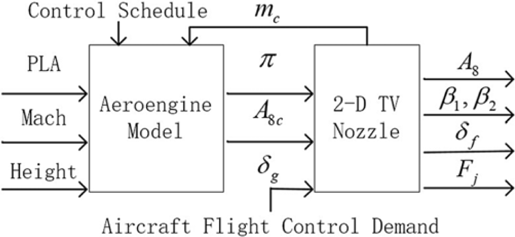
For modern aeroengines, the control of the nozzle and the engine’s operating state are, in most cases, coupled. This means a variation in the nozzle flow capacity causes the engine control system to regenerate the engine control parameters to retain the ideal cooperation of the components. With the condition that the nozzle performance in the whole flight envelope is accurately characterised, the precise prediction of the nozzle performance and proper adjusting the nozzle geometry ahead of schedule can be realised. The nozzle flow capacity’s (represented by
 ${A_{8i}}$
) deviation with that given by the engine control system (represented by
 ${A_{8c}}$
) can be kept within a small range, and hence the nozzle and engine control can be decoupled to a great extent. In this situation, the integrated engine/nozzle simulation model’s operation is accelerated, and the optimal engine’s working condition can be maintained. With the nozzle control schedule and the corresponding algorithms, the integrated aeroengine and cooled 2-D TV nozzle modeling logic when the afterburner is unlit can be established. This is shown in Fig. 13.
Integrated aeroengine/nozzle modeling logic (with the afterburner unlit).

When the afterburner is lit, air bleeding from the by-pass inevitably influences the engine’s working conditions. By precisely predicting the nozzle performance and properly controlling the nozzle geometry, the influence of the injected cooling air can be reduced and the coupling mechanism of the nozzle and the engine can be simplified. With the nozzle control schedule and the corresponding algorithms, the integrated modeling logic when the afterburner is lit can be established as shown in Fig. 14.
Integrated aeroengine/nozzle modeling logic (with the afterburner lit).

With this aeroengine/cooled 2-D TV nozzle modeling method, a 0-D aeroengine model is modified to simulate an aeroengine equipped with the cooled 2-DTV nozzle. The detailed process and results are presented in the following sections.
6.2 Application of nozzle control schedule and integrated modeling method
In this application case, a cooled 2-D TV nozzle module with nozzle control and prediction algorithms is applied to a 0-D engine model. The model is a component-level simulation model of a low BPR mixed-exhaust afterburning turbofan engine, which is able to simulate the engine’s operating state, thermal cycle parameters, and overall performance in a certain flight envelope. The original engine is equipped with an adjustable convergent nozzle, and its control system gives
 ${A_{8c}}$
once the engine operation point calculation is over. More detailed statements about the 0-D engine model are available in(Reference Hailong and Jin65).
Based on the existing 0-D engine model, the adjustable convergent nozzle is replaced by a cooled 2-D TV nozzle, and a by-pass air extraction module is added. The purpose of this application case is to verify the feasibility of the nozzle control schedule and the corresponding algorithms. This is accomplished by using the synthetic nozzle performance distribution, calculating the nozzle control parameters
 ${A_8}$
,
 ${\beta _1}$
, and
 ${\beta _2}$
, and predicting the engine’s overall performance.
6.2.1 Engine flight envelope and nozzle performance distribution
As the application case is mainly demonstrative, real engine flight envelope and nozzle experimental data are unnecessary. This paper first gives a simplified engine flight envelope. Based on the envelope, the varying ranges of
 $\pi $
and
 ${A_{8c}}$
are estimated and a synthetic nozzle performance distribution is given based on this range. With this distribution, the nozzle control and performance prediction are realised.
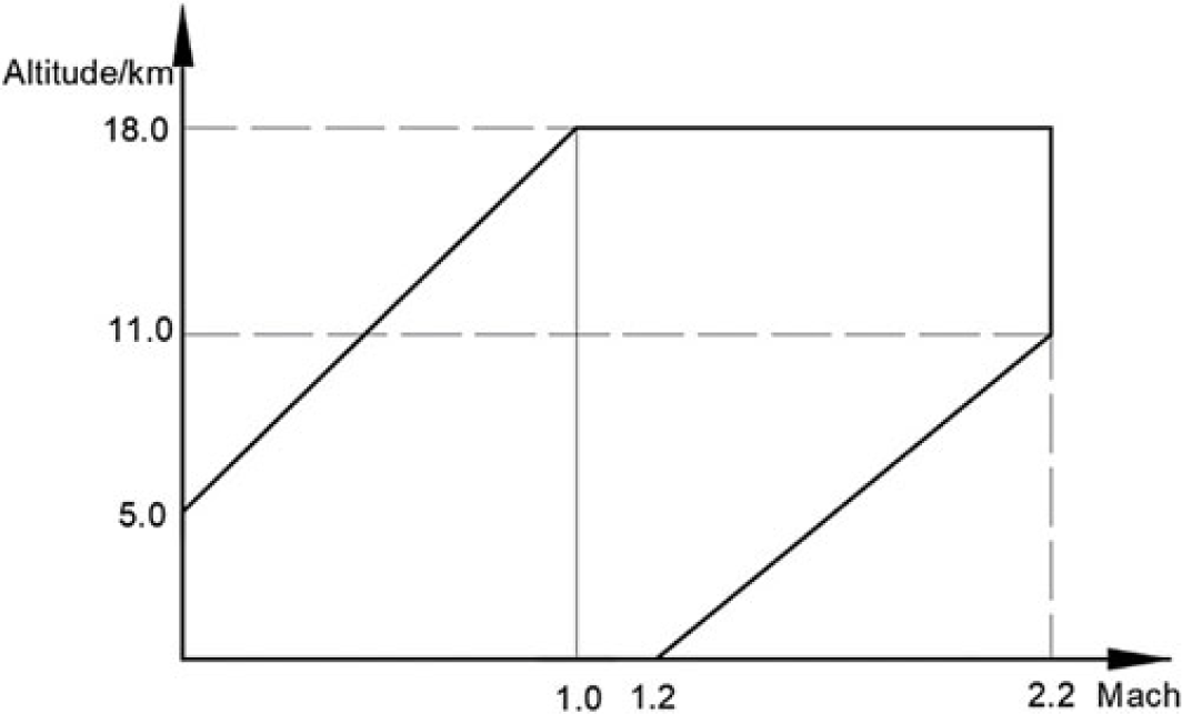
The demonstrative engine flight envelope used in this paper is shown in Fig. 15. This paper assumes that with this flight envelope, the region within the heavy lines are the flight conditions where the engine is able to work; only with afterburner lit can the engine fly supersonically.
A demonstrative engine flight envelope.

Based on the flight envelope, the engine working points with the 0-D engine model are tested. The varying ranges of
 $\pi $
and
 ${A_{8c}}$
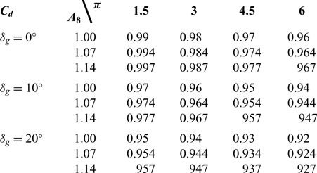
are obtained, and the demonstrative nozzle performance distribution can be given. The demonstrative nozzle discharge coefficient distribution with
 ${A_8}$
,
 $\pi $
, and
 ${\delta _g}$
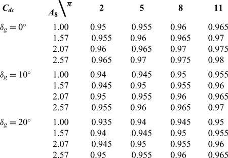
when the afterburner is lit is presented in Table 1 (
 ${A_8}$
is non-dimensionalised through the division by its minimum limit).
Demonstrative nozzle discharge coefficients with the afterburner unlit

The demonstrative nozzle discharge coefficient distribution when the afterburner is lit is presented in Table 2, while other demonstrative nozzle performance parameter distributions are presented in Appendix A.
Demonstrative nozzle discharge coefficients with the afterburner lit

Although the nozzle performance data used in this paper are synthetic and demonstrative, the generation of the nozzle performance data, such as
 ${C_{\rm{d}}}$
,
 ${{\rm{C}}_f}$
, and
 ${\delta _f}$
, to a great extent refers to the existing research achievements on TV nozzle performance simulation and experiments(Reference Wilson, Adler and Bar-Yoseph1,Reference Yang, Qitai, Wang and Zhu43,Reference Hunter44,Reference Gal-Or53) . In addition, some essential fluid dynamic principles are considered in generating the demonstrative nozzle performance. For example, as
 ${A_8}$
increases, the non-isentropic effects caused by the boundary layer at the nozzle throat diminish and
 ${C_{\rm{d}}}$
may correspondingly increase. These principles are reflected in Tables 1 and 2.
With these given nozzle performance parameters, assuming that the divergent flaps’ area
 $L$
is four times as large as the nozzle throat’s minimum area, the cooled 2-D TV nozzle module can be applied on the 0-D engine model. Hence, the feasibility of the nozzle control schedule and the corresponding algorithms can be demonstrated.
6.2.2 Results of nozzle control schedule application
Based on the 0-D engine model, the integrated aeroengine/nozzle modeling method stated in this paper is realised by programming, and the demonstrative nozzle performance distributions presented in the former section are used to predict the nozzle’s working states. By testing the modified 0-D engine model, it can be demonstrated that the nozzle control and performance prediction algorithms are consistently convergent within the flight envelope. The nozzle control parameters with four significant digits can be determined in less than ten iterations of the outermost loop in each calculation.
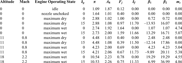
According to the test results of the modified 0-D engine model, the engine performance and the nozzle control parameters under certain typical flight points are presented in Table 3. The values of
 ${A_8}$
and the engine thrust are non-dimensionalised, and
 ${m_c}$
is divided by
 ${m_g}$
.
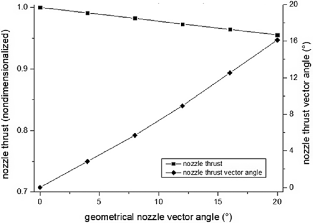
The demonstrative nozzle performance variation with
 ${\delta _g}$
under the flight conditions of 15km, Mach 1.5, and in the maximum wet state is shown in Fig. 16. The test results show that over 58% thrust enhancement is gained at the cost of an approximate 20K increment of
 $T_4^*$
over the original model, which has an adjustable convergent nozzle. In addition, less than 5.3% of the inlet air mass flow is utilised as nozzle cooling air when the fan surge margin grows from 24.9 to over 37.2 because of the by-pass air extraction.
Nozzle control parameters and engine performance under typical flight conditions

Demonstrative nozzle performance variation with
 ${\delta _g}$
.

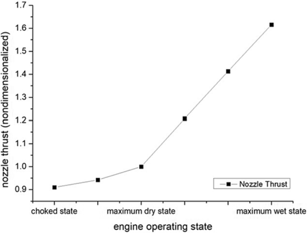
The demonstrative nozzle thrust variation with the engine’s operating state under the flight conditions of 11km, Mach 0.9, and
 ${\delta _g}$
equal to 0° is shown in Fig. 17.
Demonstrative nozzle thrust variation with engine operating state.

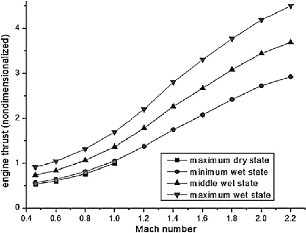
The demonstrative nozzle thrust variation with Mach number under the conditions of 11km and
${\delta _g}$
equal to 0° is shown in Fig. 18.
Demonstrative nozzle thrust variation with Mach number.

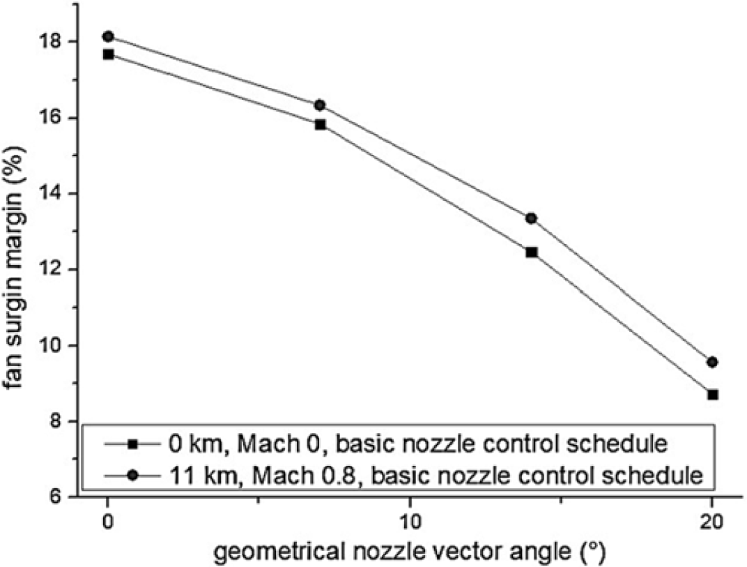
In order to explore the advantages on maintaining the engine operating stability of the nozzle control schedule put forward in this paper, fan surge margin variations with
${\delta _g}$
under certain flight conditions are tested. The testing results in the maximum dry state using the basic nozzle control schedule, which is simply deflecting the divergent flaps by
${\delta _g}$
, is shown in Fig. 19. Here, it can be seen that the nozzle deflections deteriorate the fan’s operating stability; however, with the recommended nozzle control schedule, due to the properly controlled nozzle throat area and the decoupled modeling architecture, the fan surge margin remains stable when the afterburner is unlit.
Fan surge margin variation with
 ${\delta _g}$
in the maximum dry state.

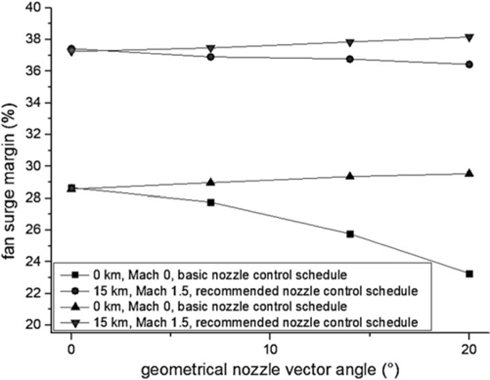
The comparison of the fan surge margin variation with
${\delta _g}$
in the maximum wet state using the basic and recommended nozzle control schedules are shown in Fig. 20. When the nozzle deflection decreases the throat area, properly controlling the nozzle geometry avoids the movement of the fan operating point toward the surge boundary. Moreover, for engines that apply the recommended nozzle control schedule, because the nozzle deflection affects the cooling air mass flow (which is increasing in this paper), the fan surge margin increases slightly. Other phenomena observed in this test include that the nozzle deflection enlarges
 $\pi $
and reduces the engine air mass flow. These outcomes all result from the nozzle throat diminution, and can be improved by applying the nozzle control schedule put forward in this paper.
Comparative fan surge margin variation with
 ${\delta _g}$
in the maximum wet state.

It can be seen that the modified 0-D engine model is satisfactorily able to predict the nozzle performance in the given flight envelope; in addition, the model can help to assess the benefits and costs of applying the nozzle. In future practical applications, with more detailed and precise nozzle performance data obtained from simulations and experiments, the reliability of the nozzle control parameters and performance predictions in the whole flight envelope can certainly be improved.
7.0 CONCLUSION
This paper mainly studies the features and performance characterisation of the cooled 2-D TV nozzle, the nozzle control schedule, and the engine/nozzle integrated modeling method. These results complement the scarce research about the TV nozzle from an overall perspective, so that aeroengine improvements and TV nozzle designs can benefit. In the paper, these conclusions are obtained:
-
1. The nozzle throat area, exit area, geometrical vector angle, and the deflection angles of the two divergent flaps are the major geometrical parameters of a 2-D TV nozzle, and three independent geometrical parameters are required to ascertain the nozzle geometry.
-
2. The deflection of the 2-D TV nozzle affects the throat area and the discharge coefficient. This causes the loss of the fan surge margin once the flow capacity is diminished for most of the mixed-exhaust engines. The extraction and injection of cooling air also affect the engine’s operating state, causing the turbine inlet temperature to rise. In view of these effects, guiding principles are needed for the design of the nozzle control schedule and the cooling scheme.
-
3. The cooled 2-D TV nozzle performance can be described with four major parameters: discharge coefficient, thrust coefficient, thrust vector angle, and cooling air mass flow coefficient. Based on the proposed nozzle cooling scheme and the constraints of
${{{A_9}} \mathord{\left/{{A_{8i}}}\right.}}$
and
$\pi $
, the nozzle performance can be predicted with three independent parameters:
${A_8}$
,
${\delta _g}$
, and
$\pi $
. -
4. A set of cooled 2-D TV nozzle control schedules is established. With the corresponding nozzle control and performance prediction algorithms, and nozzle control parameters, the values of
${A_8}$
,
${\beta _1}$
, and
${\beta _2}$
can be produced in real time; the engine’s overall performance can be predicted. -
5. According to the performance test on the engine model, the nozzle control algorithm converges in the whole flight envelope and is able to produce proper control parameters, and better and more stable engine performance is obtained. The advantages of the recommended nozzle control schedule have been demonstrated.


In summary, this paper provides an integrated methodology on the study of the 2-D TV nozzle and engine. By abiding by the nozzle performance characterisation, future nozzle simulations and experimentation may better fit the needs of overall performance designs for engines. Furthermore, the principles and conclusions obtained in study of 2-D TV nozzles is instructive in the future study of other types of TV nozzles, and more elaborate nozzle cooling schemes with corresponding nozzle performance characterisations can further improve the overall performance of engines.
FUNDING
This research is funded by National Nature Science Foundation of China (NSFC) under Grants 51776010 and National Science and Technology Major Project (2017-I-0005-0006).
APPENDIX A. Demonstrative nozzle performance parameters
The demonstrative nozzle performance parameter distributions used in the application case of the cooled 2-D TV nozzle on the 0-D engine model are presented in this appendix. Tables A1 and A2 are the demonstrative nozzle thrust coefficients. It is worth noting that because of the definition of the nozzle thrust coefficient when the afterburner is lit (Equation 18), the thrust coefficients can exceed the value of 1 under some conditions.
Demonstrative nozzle thrust coefficients with the afterburner unlit

Demonstrative nozzle thrust coefficients with the afterburner lit

The demonstrative nozzle thrust vector angle distributions are shown in Tables A3 and A4.
The demonstrative cooling air mass flow coefficient distribution is presented in Table A5.
Demonstrative nozzle thrust vector angles with the afterburner unlit

Demonstrative nozzle thrust vector angles with the afterburner lit

Demonstrative cooling air mass flow coefficients