1. Introduction
In 2015, all United Nations Member States adopted the 2030 Agenda for Sustainable Development. The agenda consists of a set of important development issues considering the three dimensions of sustainable development – economic, social, and ecological. The end goal of the agenda is to end poverty, fight against inequality, tackle climate change, and build peaceful societies that respect human rights. Among all, agriculture and the fight against inequality are two very important topics.
“The world’s population is expected to continue growing for another 50 or 60 years, reaching a peak of around 10.3 billion people in the mid-2080s, up from 8.2 billion in 2024,” according to the World Population Prospects 2024 by the United Nations Department of Economic and Social Affairs, Population Division [27]. Consequently, food production must increase in the near future. At the same time, growing agricultural activity compromises environmental sustainability by wasting and overusing fertilizer, irrigation water, and other phytosanitary products [Reference Ramankutty, Mehrabi, Waha, Jarvis, Kremen, Herrero and Rieseberg40]. Traditional agriculture’s standard management practices ignore the range of crop conditions and demands within a field in favor of the constant application of agrochemicals and water [Reference Corti, Gallina, Cavalli, Ortuani, Cabassi, Cola, Vigoni, Degano and Bregaglio10]. This strategy is no longer practical on a global scale for attaining high output levels while minimizing environmental harm; therefore, new sustainable options, like precision agriculture [Reference Ofori, Griffin and Yeager28], need to be put forth and into practice.
As of 2021, approximately
 $1.3$
billion people – approximately
 $16$
% of the global population – have disabilities, according to the World Health Organization’s Global Report on Health Equity for Persons with Disabilities [29]. According to the United Nations’ 2018 Disability and Development Report [26],
 $1$
% of people worldwide requires a wheelchair for everyday mobility. The report also presents information about wheelchair-accessible facilities. About
 $20$
% of hospitals and
 $32$
% of pharmacies are not wheelchair accessible, according to crowd-sourced data primarily from wealthy nations. Additionally, only
 $47$
% of educational facilities and
 $69$
% of public restrooms are accessible for people in wheelchairs. The 2030 Agenda for Sustainable Development recognizes that, in order to accomplish all 17 goals, disability must be taken into account as a cross-cutting issue.
Against this context, researchers in robotics are working to develop systems that can help our society address these global challenges. Regarding precision agriculture, the contributions are usually categorized in two groups [Reference Botta, Cavallone, Baglieri, Colucci, Tagliavini and Quaglia5]: enabling technologies, such as structural characterization [Reference Chen, Zhu and Ozkan, “7], plant/fruit detection [Reference Gongal, Silwal, Amatya, Karkee, Zhang and Lewis12], physiology assessment, and novel robotic systems [Reference Maes and Steppe18, Reference Nguyen, Kayacan, De Baedemaeker and Saeys24, Reference Schor, Bechar, Ignat, Dombrovsky, Elad and Berman41]. In the field of electric-powered wheelchairs, many researchers have investigated autonomous navigation techniques [Reference Niijima, Sasaki and Mizoguchi25, Reference Wang, Matveev, Savkin, Nguyen and Nguyen51], proposed novel omnidirectional systems to overcome the mobility limitation of conventional wheelchairs [Reference Kundu, Mazumder, Lenka and Bhaumik15, Reference Tagliavini and Quaglia45], and new designs to overcome architectural barriers [Reference Podobnik, Rejc, Slajpah, Munih and Mihelj38, Reference Quaglia, Franco and Oderio39].
Despite the growing popularity of autonomous navigation, many applications still heavily rely on manual driving. Control interfaces are therefore essential parts of motorized systems, and the user experience is greatly influenced by their quality and design. Regarding motorized wheelchair manual control, lots of attention has been directed to driving interfaces designed to adapt to the user’s needs. Control interfaces for manual wheelchairs may be classified into conventional joystick-based devices [43] and alternative interfaces [Reference Ghorbel, Amor and Jallouli11]. Joystick-based systems are the most commonly adopted system due to their simplicity, cost-effectiveness, reliability, and wide dissemination. To facilitate the use of these systems, different types of handles can be found on the market. Some examples are soft-balls [34], T-handles [36], stick-based [35], dome-shaped [30], and U-shaped interfaces [31], and large-ball [33] and chin cup joysticks [32]. However, in those cases where users cannot use conventional interfaces, alternative solutions could be adopted. In literature, many alternatives have been proposed such as EEG and ECG interfaces [Reference Andaluz, Ortiz, Chicaiza, Varela, Espinosa and Canseco2, Reference Cao, Li, Ji and Jiang6, Reference Lin and Cheng-Hung17, Reference Tonin, Perdikis, Kuzu, Pardo, Orset, Lee, Aach, Schildhauer, Martínez-Olivera and d. R. Millán48], sip-and-puff interfaces [Reference Mougharbel, El-Hajj, Ghamlouch and Monacelli22], voice-based interfaces [Reference Katevas, Sgouros, Tzafestas, Papakonstantinou, Beattie, Bishop, Tsanakas and Koutsouris13, Reference Levine, Bell, Jaros, Simpson, Koren and Borenstein16, Reference Walter, Hemachandra, Homberg, Tellex and Teller50], tongue-based interfaces [Reference Kim, Park, Bruce, Sutton, Rowles, Pucci, Holbrook, Minocha, Nardone, West and Laumann14], head movement interfaces [Reference Berjón, Mateos, Barriuso, Muriel and Villarrubia3, Reference Taher, Amor, Jallouli, Hammouda and Dghim46], and gaze tracking interfaces [Reference Plesnick, Repice and Loughnane37, Reference Thakur and Kulshrestha47].
All these interfaces are designed for the person sitting in the wheelchair. Comparatively less attention has been given to interfaces tailored for caregivers. Caregiver control interfaces typically fall into two categories: position-based (e.g., joysticks or remote controllers) and force-based systems (e.g., the handlebar designed for the ASBGo walker [Reference Martins, Santos, Seabra, Frizera and Ceres19], the work done by Trujillo et al. [Reference Trujillo-León, Bachta, Castellanos-Ramos and Vidal-Verdú49], and SensHB.Q). While position-based interfaces are cost-effective and reliable, they require the user to understand how input motions relate to system movements. Moreover, accurate angle position control can be challenging when the joystick base is fixed to the moving system. Although remote controllers, such as wireless game pads, eliminate this specific issue, they still require users to learn the input-to-motion mapping. This relationship between the joystick rotations and the system motion is not always intuitive, especially in omnidirectional systems interfaces where three-axis or multiple 2D joysticks are used. Similar studies with joystick-like interfaces have also been conducted for smart-walkers [Reference Martins, Frizera-Neto, Santos and Ruíz20] and are commercially available for industrial transportation systems.
As an alternative, force-based control interfaces offer a more intuitive experience since they replicate how humans typically move objects – applying forces and torques based on the desired movement. These interfaces are made of handles that have force sensors placed between the user’s hand and the motorized system to be controlled. With this configuration, the user’s forces and torques are measured and transformed into reference signals for the motorized system. The use of sensorized handlebars for motorized wheelchair control was investigated by Trujillo et al. [Reference Trujillo-León, Bachta, Castellanos-Ramos and Vidal-Verdú49] and Alwan et al . [Reference Alwan, Ledoux, Wasson, Sheth and Huang1]. Similar approaches have been proposed for smart-walkers, such as in ref. [Reference Martins, Santos, Seabra, Frizera and Ceres19]. These kinds of interfaces can also be found in patent literature about industrial robotic arms [Reference Murakami23] and medical beds [Reference Blanchard, Thompson, Wrobleski and Smith4]. Existing force-sensitive interfaces have two main limitations: (1) they control only two degrees of freedom (suitable for differential steering wheelchairs or walkers [Reference Cortes, Martínez-Velasco, Barrué, Martin, Campana, Annicchiarico and Caltagirone9, Reference Martins, Santos, Seabra, Frizera and Ceres19, Reference Shi, Cao, Leng and Tan42]), or (2) they rely on expensive six-axis force–torque sensors [Reference Alwan, Ledoux, Wasson, Sheth and Huang1, Reference Trujillo-León, Bachta, Castellanos-Ramos and Vidal-Verdú49]. The former is inadequate for omnidirectional control, while the latter is not cost-effective for widespread use.
In [Reference Tagliavini, Botta, Colucci, Baglieri, Duretto and Quaglia44], the authors proposed the first prototype of SensHB.Q, a drive interface for omnidirectional motorized systems that adopts only three uniaxial load cells. The adoption of only uniaxial load cells makes the interface more affordable when compared to interfaces based on six-axis force–torque sensors. In the current state of the art, SensHB.Q fills the gap of force-sensitive interfaces by developing a device that is both cost-effective and suitable for the control of omnidirectional (i.e., with three degrees of freedom) electric-powered systems such as wheelchairs and mobile robots. This paper is the extended version of ref. [Reference Tagliavini, Botta, Colucci, Baglieri, Duretto and Quaglia44]; it presents a new version of the handlebar in which conventional revolute joints have been replaced with flexure hinges. This design change reduces friction, lowers the number of components, and simplifies assembly. The key features of this new design of SensHB.Q are presented in Section 2; then, the force-sensitive interface is tested with two motorized systems, namely, the electric-powered wheelchair MoviWE.Q [Reference Tagliavini and Quaglia45] and the omnidirectional rover for greenhouses Agrimaro.Q [Reference Colucci, Botta, Tagliavini, Baglieri, Duretto and Quaglia8]; the kinematic model of the two motorized systems is presented in Section 3, while the experimental results are discussed in Section 4.
2. SensHB.Q design and prototyping
2.1. Concept
The first step in the design process of the device is the definition of the design requirements. In particular, the force-sensitive drive interface should have the following characteristics:
-
• intuitive to use, ideally, no training should be required;
-
• limited cost;
-
• the system must generate at least three reference signals that are used to command the planar motion of the omnidirectional motorized system;
-
• the system must be able to filter out inputs generated by accidental impacts.
Concept representation of the SensHB.Q: inputs and reference frames definition.

Based on these requirements, the concept design of the device can be developed. To address the first requirement, force/torque inputs are selected for the drive interface to mimic the way we move the objects around: we apply forces and torques according to the desired motion we want to obtain. Therefore, the system must be able to measure the forces and torques applied by the driver on the device. For this reason, this document refers to this device as a sensorized handlebar. To measure the force/torque applied by the caregiver on the handlebar, the system must adopt force/torque sensors. The simplest solution could be to use a six-axis force/torque sensor and only take into account the desired components of the applied wrench. However, six-axis force/torque sensors are very expensive. To limit the cost of the system, only single-axis load cells are used. For reference, the selected uniaxial load cells cost around
 $167$
€, while size equivalent six-axis force/torque sensors are in the range of
 $5000$
€ to
 $12,000$
€ considering brands like BOTA SYSTEMS, Kistler, and Futek. To function properly, single-axis load cells need to be loaded on their measurement axis. For this reason, SensHB.Q is based on a planar mechanism that is isostatically constrained by the uniaxial load cells. In this way, only the desired components of the applied wrench are measured, while the others are supported by the structure of the mechanism.
SensHB.Q is designed to control the movements of a generic omnidirectional mobile system but can also work with systems with limited mobility, such as platforms with differential steering. To control omnidirectional movements, the system must be able to generate at least three reference signals. In the case of planar omnidirectional motion, the most intuitive set of wrench components to use consists of the linear force components
 $F_x$
and
 $F_y$
and the torque
 $M_z$
, as shown in Fig. 1.
 $F_x$
and
 $F_y$
are the components of the linear force in the plane
 $XY$
of the frame
 $\{h\}$
, which is parallel to the plane of motion of the motorized system, while the torque
 $M_z$
is the torque about the axis perpendicular to the plane of motion.
The main idea behind this device can be generalized as follows:
-
• If only uniaxial load cells are used to lower the costs, a mechanism must be designed to properly load the force sensors.
-
• The mechanism should have the same number of degrees of freedom as the system to be controlled, with the degrees of freedom aligned with the direction of the selected force/torque inputs.
-
• Uniaxial load cells should be attached to constrain the mechanism isostatically. In this way, only the components of interest are measured by the load cells, while the other components of the wrench are supported by the structure of the mechanism.
-
• The design should limit the influence of assembly inaccuracies on measurement errors.
2.2. Functional design
Multiple mechanism architectures were considered during the functional design of the force-sensitive handlebar. Six of the most promising solutions among all the considered ones are presented in Fig. 2. In Fig. 2, symbols and acronyms are adopted: the uniaxial load cells from 1 to 3 are named LC1, LC2, and LC3; the handlebar reference frame is
 $\{h\}$
. Moreover, a complete joint and link nomenclature is defined for the final design presented in Fig. 2(f). Revolute joints are labeled with capital letters (fixed joints have the subscript
 $0$
), while the link
 $i$
is named
 $lk_i$
with
 $i = 0, \ldots 5$
.
Proposed mechanisms for SensHB.Q: (a) version with a six-axis force sensor; (b) four-bar-like mechanism with three one-axis load cells, four prismatic joints, and two revolute joints; (c) spatial mechanism with three one-axis load cells and spherical and revolute joints; (d) six-bar mechanism; (e) six-bar mechanism with a different load cell arrangements; (f) six-bar with load cells mounted to lower the coupling between the measurements.

System (a) is the solution already proposed in the literature. A six-axis force–torque sensor is mounted between the handlebar and the motorized system to be controlled. These sensors are commonly used in collaborative robotics to measure the forces and torques that occur during the interaction between the robot’s end-effector and its environment. The main advantage of this solution is the simplicity and quality of the measurements, but the high cost makes this solution unsuitable for this device.
Solution (b) uses three uniaxial load cells mounted on a planar mechanism with three degrees of freedom. The mechanism consists of four prismatic and two revolute joints. The main advantage of this solution is the low cost associated with single-axis load cells. However, this solution is characterized by a high mechanical complexity (high number of kinematic pairs), and the operation of the system is highly dependent on friction.
Solution (c) uses three single-axis load cells attached to a spatial joint mechanism. The mechanism consists of two swivel joints, four ball joints, and six binary links. With this arrangement of links and joints, the link can move freely in the
 $XY$
plane and rotate around the
 $z$
-axis of the
 $\{h\}$
frame. This solution has the same advantages as solution (b), namely, limited costs associated with uniaxial load cells, but it is characterized by high mechanical complexity and a higher encumbrance.
The solution (d) is based on a linkage with six bars constrained by three uniaxial load cells. The main advantage of this arrangement is the low cost associated with the use of uniaxial load cells, a relatively simple mechanical structure, and a reduced encumbrance in the
 $z$
direction compared to solution (c). The main disadvantage is the high lateral encumbrance due to the fixed ball joint along the
 $x$
-axis of
 $\{h\}$
.
In order to limit the lateral encumbrance, solution (e) adopts a slightly different arrangement of the load cells. However, this arrangement of the load cells has the disadvantage that the measurements of LC2 and LC3 are misaligned with the direction of the loads to be measured. Therefore, an appropriate experimental characterization of the sensor-controlled control arm is required, as the measurements are closely related to the mounting accuracy.
Finally, solution (f) was designed to limit the lateral encumbrance on the mechanism and to take advantage of a particular state of the six-bar linkage to improve measurement accuracy. To better describe how the configuration of the mechanism improves the measurements, let us imagine that we remove the three load cells. Due to the position of the mechanism, a small displacement of revolute joints B and C along the
 $y$
-axis does not change the distance between the attachment point of LC3. Similarly, a small displacement of revolute joints B and C along the
 $x$
-axis does not change the distances between the attachment points of LC1 and LC2. For this reason, the measurements can be considered decoupled so that the influence of the mounting accuracy on the load measurements is less. Due to these advantages, configuration (f) is selected for the wheelchair prototype.
As a final remark about the functional design of SensHB.Q, it is important to underline that, in this work, the term “intuitive” is used to refer to the fact that, ideally, the driver shouldn’t need any training to use the interface. With SensHB.Q, the two sufficient information that the driver has to know are: the hands must be placed on the ergonomic grips, and the system behaves like an empty shopping cart. This intuitive requirement is not satisfied in three-axis joysticks, where the users must understand the joystick map to drive. Usually, this becomes natural in time, but still, the driver has to convert in his/her head the desired motion into rotations of the joystick. With SensHB.Q, this is not needed as the system behaves like any other object on a plane; for this reason, the interface is defined “intuitive” in this paper. Of course, the term intuitive also has a practical meaning that needs experimental user experience evaluation to be addressed. These evaluations will be the objective of further experimental analysis, but they go beyond the scope of the present work.
2.3. Prototype
This section describes the SensHB.Q prototype, displayed in Fig. 3. The prototype is made of three commercial single-axis load cells, model FLAE-100N produced and calibrated by Forsentek Co., aluminum profiles, and 3D-printed components. The revolute joints are made with spring-steel metal bands used as flexure hinges. Compliant revolute joints have been proven to be very appropriate for this kind of application where a very small range of motion is required and friction in kinematic pairs must be as low as possible.
(a) SensHB.Q prototype, (b) top view with the functional scheme in transparency.

The load cell raw signals are amplified with the amplifier LC3A(0-2.5-5V)-24V by Forsentek Co. The output signals are three analog voltages in the range
 $[0,\,+ 5]$
V. SensHB.Q is designed as an independent drive interface; thus, a dedicated drive interface was developed. The dedicated electronic unit is designed around an Arduino UNO Rev4 micro-controller (
 $\mu$
C). The
 $\mu$
C reads the amplified load cells’ signals and the state of the capacitive switches through the CAP1188 Capacitive Touch Sensor Breakout by Adafruit. If at least one capacitive switch for each handle is touched, the handlebar is enabled, and the force measurements
 $F_{lc_1}$
,
 $F_{lc_2}$
, and
 $F_{lc_3}$
are converted into the three wrench components
 $F_x$
,
 $F_y$
, and
 $M_z$
with respect to the
 $\{h\}$
reference frame. Then, the wrench components are transposed into the reference frame of mobile system
 $\{b\}$
, and the velocity twist reference is computed. The corresponding transfer function is detailed in Section 2.4. The outputs of SensHB.Q are two digital signals (device is powered on/off, and the driver is/isn’t grasping the handlebar) and three analog signals proportional to the twist velocity components
 $\dot {\gamma }_b$
,
 $\dot {x}_b$
, and
 $\dot {y}_b$
. If needed, the electronic unit can be reprogrammed to communicate through different digital communication protocols, such as Serial, SPI, I2C, or CAN.
2.4. Transfer function
The way in which force and torque measurements are used to generate commands for the moving system – that is, the transfer function that generates the motion control signals for the motorized system from the input wrench applied to the interface – is a critical component for the operation of the force-sensitive drive interface. Many approaches can be used to compute the velocity twist reference. In this case, the measured wrench components are used as inputs to a simplified dynamic model, and the resulting velocity twist is used as the velocity twist reference for the motorized system to be controlled. In this way, the driver should find that the system behaves as a reference dynamic system. In this case, an empty trolley is considered the reference system. The basic assumption is that it should be easy for the driver to control the motorized system if he/she has some experience with the system used as reference behavior, regardless of which system it is. With this approach, undesirable dynamic behavior, such as the influence of the steering wheels, can be neglected. Under this assumption, the empty car can be modeled as a box sliding on a plane with Coloumb-like friction.
The velocity twist of the empty trolley
 $\mathbf{x} = \begin{bmatrix}\dot {\gamma }_b & \dot {x}_b & \dot {y}_b \end{bmatrix}^T$
is used to describe the state of the model. The position and yaw rotation of the trolley are neglected in the state vector since the goal is to control the instantaneous velocity twist of the motorized system. The input vector of the model is the two-dimensional wrench
 ${W_{user}} = {\begin{bmatrix}M_{z,user} & F_{x,user} & F_{y,user} \end{bmatrix}^T}$
applied by the driver to the force-sensitive interface, as shown in Fig. 4. It is assumed that the center of gravity is at the origin of the reference frame
 $\{b\}$
, the mass of the trolley is
 $m$
, and the moment of inertia about the
 $z$
-axis of
 $\{b\}$
is
 $I_z$
. Further assumptions include plane motions, that is, rotations and torques outside the plane are neglected, the weight distribution of the trolley is uniform, and the coefficient of friction is constant.
Dynamic model representation: the components of the applied wrench input are shown in purple; the components of the computed velocity twist are displayed in green; the friction force and torque are shown in red.

Coulomb dry friction is assumed for the contact between the trolley and the ground. The static and kinetic coefficients of friction are
 $\mu _s$
and
 $\mu _k$
. Gravity acts along the negative
 $z$
-axis of
 $\{b\}$
so that the vertical reaction force exerted by the ground on the trolley is
 $\mathbf{N} = mg \hat {z}$
. The friction force acting on the system is
 $\mathbf{F}_f = F_f \hat {\mathbf{F}}_f$
. The direction of the friction force
 $\hat {\mathbf{F}}_f$
is opposite to the linear velocity
 $\mathbf{v} = \begin{bmatrix}\dot {x}_b & \dot {y}_b & 0 \end{bmatrix}^T$
if the system is moving, or it is opposite to the applied linear force if
 $\mathbf{v} =\mathbf{0}$
. The limiting friction force is
 $F_{f,max} = \mu _s m g$
. As far as the yaw rotation is concerned, we consider the contact surface between the ground and the trolley as a thin ring with radius
 $r_f$
. Thus, the limiting moment of friction is
 $M_{f,max} = \mu _s m g \,r_f$
. If the trolley is not moving, the frictional torque is opposite to the applied torque, while
 $M_{f} = \mu _k m g\,r_f$
in the opposite direction of the yaw velocity when the carriage is turning. Under these assumptions, the equilibrium of the box can be described as follows:
 \begin{align} \begin{cases} I_z \ddot {\gamma }_b - \mathbf{M}^T_f \hat {z} = M_{z,user} + l_3 F_{x,user} \\[3pt] m \ddot {x}_b - \mathbf{F}_{f}^T \, \hat {x} = F_{x,user} \\[3pt] m \ddot {y}_b - \mathbf{F}_{f}^T \, \hat {y}= F_{y,user} \end{cases} \quad \leftrightarrow \quad M \dot {\mathbf{x}} + f(\mathbf{x}) = \Gamma {W_{user}} \end{align}
where
 $M$
is the mass matrix,
 $ f(\mathbf{x})$
collects the friction contributions, and
 $\Gamma {W_{user}}$
is the driver input wrench contribution. In particular, the matrices
 $M$
and
 $\Gamma$
can be written as:
 \begin{align} M = \begin{bmatrix} I_z &\quad 0 &\quad 0 \\ 0 &\quad m &\quad 0 \\ 0 &\quad 0 &\quad m \end{bmatrix}; \qquad \Gamma = \begin{bmatrix} 1 &\quad l_3 &\quad 0 \\ 0 &\quad 1 &\quad 0 \\ 0 &\quad 0 &\quad 1 \end{bmatrix}; \end{align}
Solving Eq. (1) in the discrete-time domain, the state estimator equation can be written as in (3).
 \begin{equation} \mathbf{x}(k+1) = \mathbf{x} (k) + M^{-1} (\Gamma {W_{user}} - f(\mathbf{x})) dt \end{equation}
Using (3), it is possible to compute the new state of the system
 $\mathbf{x}(k+1)$
based on the current state
 $\mathbf{x}(k)$
and the wrench input
 $W_{user}$
. The new state of the system is used as the velocity twist reference of the motorized system.
3. Mobile platforms kinematic model
To test the functioning of the SensHB.Q, experimental tests have been conducted using SensHB.Q to drive the omnidirectional wheelchair MoviWE.Q and the rover for precision agriculture in greenhouses Agrimaro.Q. These two motorized systems are shown in Fig. 5. MoviWE.Q is an omnidirectional electric-powered wheelchair designed for indoor navigation. This motorized system can navigate in environments with obstacles and narrow passages due to its improved mobility with respect to conventional differential wheeled wheelchairs. Agrimaro.Q is a three-wheeled omnidirectional robot designed for precision agriculture in greenhouses. This rover has a track-adjustment mechanism based on Scott–Russell linkage to navigate within different protected crop cultivation, also allowing a compact configuration when not used.
The omnidirectional wheelchair MoviWE.Q (a) and the rover for greenhouses Agrimaro.Q (b).

The kinematic model of MoviWE.Q and Agrimaro.Q is shown in Fig. 6. Both systems have omnidirectional mobility based on swerve-drive locomotion systems. MoviWE.Q has two swerve-drive units, while Agrimaro.Q has three. To provide stability without the use of complex self-balancing control systems, MoviWE.Q uses other two passive castor wheels with an integrated suspension system to avoid problems related to four contact points. In this section, the kinematic model of the two systems is presented to derive the relationship between the desired input velocity twist and the actuation variables. This inverse kinematic model is implemented in the control units of the motorized systems. Regarding MoviWE.Q, the following kinematic model does not include the passive castor wheels since they are not part of the locomotion systems.
Kinematic representation of the locomotion systems of MoviWE.Q (a) and Agrimaro.Q (b).

Each swerve-drive unit
 $i$
(
 $i = 1, 2, \ldots , n$
) consists of a motor-wheel mounted on a vertical steering fork and actuated by a steering motor. Thus, each swerve-drive unit (also referred to as a locomotion unit in this text) has two degrees of actuation: the wheel rotation
 $\theta _i$
around its own axis and the vertical steering angle
 $\delta _i$
. The wheel axis and the steering axis of each swerve-drive unit are incident; that is, the wheel-ground contact point is on the steering axis.
The system can be modeled as a rigid body in the plane of motion, which is considered parallel to the perfectly flat and smooth ground. If out of the plane rotations and translations are neglected, the body is free to move on the
 $XY$
plane of the
 $\{s\}$
reference frame (rf). The pose of the body with respect to (wrt) the fixed-space frame
 $\{s\}$
is defined by a position vector
 $\mathbf{p} = \begin{bmatrix}x_b & y_b & 0\end{bmatrix}^T$
where
 $x_b$
and
 $y_b$
are the coordinate of the center of
 $\{b\}$
wrt
 $\{s\}$
and a vector of Euler angles (body-
 $XYZ$
)
 $\begin{bmatrix}0 & 0 & \gamma _b\end{bmatrix}^T$
, equivalent to the orientation matrix
 $^s{R}_b = Rot(z,\gamma _b)$
that expresses the orientation of frame
 $\{b\}$
wrt frame
 $\{s\}$
. The angle
 $\gamma _b$
and the coordinates
 $x_b$
and
 $y_b$
are not displayed in Fig. 6, but their definition is unique based on this description.
The velocity twist of the system is
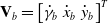 $\mathbf{V}_b = \begin{bmatrix} \dot {\gamma }_b & \dot {x}_b & \dot {y}_b \end{bmatrix}^T$
. The goal of this kinematic model is to derive the relationship between the space velocity twist
 $\mathbf{V}_b$
and the actuation vector
 $\mathbf{q}=\begin{bmatrix}q_1^T&q_2^T&\ldots &q_n^T \end{bmatrix}^T$
, where
 $q_i=[\theta _i,\delta _i ]^T$
.
The position of the center of the generic locomotion unit
 $i$
wrt the body frame
 $\{b\}$
is described by the two-dimensional vector
 $\mathbf{p}_i = \begin{bmatrix}x_i & y_i & 0\end{bmatrix}^T$
. This point is considered the attachment point of the swerve-drive unit to the system chassis. Under the assumption of a rigid body, the velocity of the center points of the locomotion unit i can be evaluated as:
 \begin{align} \dot {\mathbf{p}}_i = \dot {\mathbf{p}} + \begin{bmatrix}0 \\ 0\\ \dot {\gamma }_b \end{bmatrix} \times \mathbf{p}_i = \begin{bmatrix} -y_i &\quad 1 &\quad 0 \\ x_i &\quad 0 &\quad 1 \\ 0 &\quad 0 &\quad 0 \end{bmatrix}\mathbf{V}_b = \mathbf{h}_i \mathbf{V}_b \end{align}
At the same time, under the assumption of pure-rolling constraint, the velocity of the center points of the locomotion unit
 $i$
can be evaluated as:
 \begin{equation} \dot {\mathbf{p}}_i = r \begin{bmatrix}c_{\delta _i}\\ s_{\delta _i}\\ 0 \end{bmatrix} \dot {\theta }_i = \mathbf{s}_i \dot {\theta }_i \end{equation}
where
 $c_{\delta _i }=\cos (\delta _i )$
and
 $s_{\delta _i }=\sin (\delta _i )$
and
 $r$
is the wheel radius. Given (4) and (5), the following relationship can be written:
 \begin{equation} \mathbf{h}_i \mathbf{V}_b = \mathbf{s}_i \dot {\theta }_i \end{equation}
If all locomotion units are considered, the kinematic relationship between the velocity twists
 $\mathbf{V}_b$
and the actuation variables
 $\mathbf{q}$
can be expressed as in (7).
 \begin{align} \begin{bmatrix} \mathbf{h}_1 \\[5pt] \mathbf{h}_2 \\[5pt] \vdots \\[5pt] \mathbf{h}_n \end{bmatrix} \mathbf{V}_b = \begin{bmatrix} \mathbf{s}_1 & \mathbf{0} & \cdots & \mathbf{0} \\[5pt] \mathbf{0} &\quad \mathbf{s}_2 &\quad \cdots &\quad \mathbf{0} \\[5pt] \vdots &\quad \vdots &\quad \ddots &\quad \vdots \\[5pt] \mathbf{0}&\quad \mathbf{0} &\quad \cdots &\quad \mathbf{s}_n \end{bmatrix}\begin{bmatrix} \dot {\theta }_1 \\[5pt] \dot {\theta }_2 \\[5pt] \vdots \\[5pt] \dot {\theta }_n \end{bmatrix} \quad \Leftrightarrow \quad H\, \mathbf{V}_b = S(\mathbf{\delta })\,\dot {\mathbf{\theta }} \end{align}
where
 $\mathbf{\delta } = \begin{bmatrix}\delta _1 & \delta _2 & \cdots & \delta _n\end{bmatrix}^T$
. The matrix
 $H$
depends only on the location of the swerve-drive units wrt the
 $\{b\}$
frame, while the matrix
 $S(\mathbf{\delta })$
is state-dependent. In fact, for swerve-drive systems, it is impossible to derive a linear transformation that maps the actuation vector
 $\mathbf{q}$
into the velocity twist of the system
 $\mathbf{V}_b$
. The matrix
 $H$
is a
 $2n \times 3$
matrix, while the
 $S$
matrix is a
 $2n \times n$
matrix. The matrix
 $H$
and
 $S$
for MoviWE.Q and Agrimaro.Q are shown, respectively, in (8) and (9).
 \begin{align} H = \begin{bmatrix}-w/2 &\quad 1 &\quad 0 \\[5pt] 0 &\quad 0 &\quad 1 \\[5pt] w/2 &\quad 1 &\quad 0 \\[5pt] 0 &\quad 0 &\quad 1 \end{bmatrix}; \qquad S = \begin{bmatrix}c_{\delta _1} &\quad 0 \\[5pt] s_{\delta _1} &\quad 0 \\[5pt] 0 &\quad c_{\delta _2} \\[5pt] 0 &\quad s_{\delta _2} \\ \end{bmatrix} \end{align}
 \begin{align} H = \begin{bmatrix}-w/2 &\quad 1 &\quad 0 \\[5pt] 0 &\quad 0 &\quad 1 \\[5pt] w/2 &\quad 1 &\quad 0 \\[5pt] 0 &\quad 0 &\quad 1 \\[5pt] 0 &\quad 1 &\quad 0 \\[5pt] t &\quad 0 &\quad 1\end{bmatrix}; \qquad S = \begin{bmatrix}c_{\delta _1} &\quad 0 &\quad 0 \\[5pt] s_{\delta _1} &\quad 0 &\quad 0\\[5pt] 0 &\quad c_{\delta _2} &\quad 0\\[5pt] 0 &\quad s_{\delta _2} &\quad 0 \\[5pt] 0 &\quad 0 &\quad c_{\delta _3} \\[5pt] 0 &\quad 0 &\quad s_{\delta _3} \\ \end{bmatrix}\end{align}
From (7), the forward kinematic equation can be written as:
 \begin{equation} \mathbf{V}_b = H^{\dagger } S(\mathbf{\delta })\dot {\mathbf{\theta }} \end{equation}
where
 $ H^{\dagger }$
is the pseudo-inverse of the
 $H$
matrix. Therefore, given the actuation variables
 $\mathbf{q}$
, it is possible to compute the velocity twist of the system. It is important to underline that the actuation variables
 $\delta$
and
 $\theta$
must be chosen according to the kinematic constraint following kinematic constraint (11).
 \begin{equation} \forall i \neq j,\quad \dot {\mathbf{p}}_i^T \left (\mathbf{p}_i - \mathbf{p}_j\right ) = \dot {\mathbf{p}}_j^T \left (\mathbf{p}_i - \mathbf{p}_j\right ) \end{equation}
The inverse kinematics of the system can be solved by considering each locomotion unit independently. Given the desired velocity twist, the velocity
 $\dot {\mathbf{p}}_i$
of point
 $\mathbf{p}_i$
can be evaluated through (4). The norm of the velocity vector can be computed as
 $|\dot {\mathbf{p}}_i |=\sqrt {\dot {\mathbf{p}}_i^T \, \dot {\mathbf{p}}_i}$
, and therefore, the actuation variables associated to the locomotion unit
 $i$
can be evaluated as:
 \begin{equation} \begin{cases} \delta _i &= \text{atan2}\left ( \dot {y}_b / |\dot {\mathbf{p}}_i |,\, \dot {x}_b/ |\dot {\mathbf{p}}_i |\right )\\[5pt] \dot {\theta }_i &= (\!-\!1)^k |\dot {\mathbf{p}}_i |/r \end{cases} \end{equation}
where
 $k \in \mathbb{N}$
. For
 $\delta _i \in (\!-\!\pi,\,\pi ]$
, there are two possible solutions of the inverse kinematic problem for each drive system. This is in accordance with the physics of the system: the velocity of the center of the wheel is the same if the wheel turns
 $180^\circ$
around the vertical steering axis and it spins in the opposite direction.
4. Experimental tests
This section presents the experimental tests conducted to validate the effectiveness of the SensHB.Q force-sensitive interface. Specifically, the interface was used to control two omnidirectional robotic platforms: the MoviWE.Q power wheelchair and the Agrimaro.Q rover for precision agriculture. The two systems have the following approximate masses: MoviWE.Q
 $41$
kg, with an additional
 $20$
kg of dead weight placed on the chair, while Agrimaro.Q weighs approximately
 $100$
kg.
The model parameters employed during testing are listed in Table I. These parameters were manually tuned by the authors prior to the experiments to obtain the desired system behavior. Although exploring automatic parameter tuning methods would be a valuable direction for future work, it lies outside the scope of this paper.
Motorized system maximum velocities and model parameters used during the experimental tests.

4.1. MoviWE.Q: experimental tests
To evaluate the effectiveness of SensHB.Q on the omnidirectional wheelchair MoviWE.Q, two types of tests were conducted. In all tests, participants were instructed to move the wheelchair from a designated start position to an end position, as illustrated in Fig. 7(a). Two input types were tested: in the first set of trials, the participant controlled the wheelchair using the SensHB.Q force-sensitive interface; in the second set, a standard three-axis joystick was used. In both cases, the driver walked behind the wheelchair during operation. Figures 7(b) and (c) show the experimental setup and the wheelchair equipped with the SensHB.Q interface mounted on the backrest. During the second set of tests, the joystick was fixed to the backrest in the same position where SensHB.Q was installed. During the trials with SensHB.Q, both the applied forces (inputs to SensHB.Q) and the generated velocity twist reference signals (outputs of SensHB.Q) were recorded. For the joystick-controlled trials, only the generated velocity twist reference signals were recorded.
It is important to note that the joystick generates velocity commands based on a mapping function that converts the tilt angles of the lever into motion commands. Specifically, the direction in which the joystick lever is tilted corresponds to the direction of the linear velocity vector, the magnitude of the tilt determines the linear velocity’s magnitude, and the rotation of the joystick knob is proportional to the yaw angular velocity. This configuration was selected to enable a meaningful comparison between SensHB.Q and a commercially available interface commonly used for omnidirectional motorized systems.
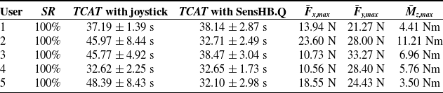
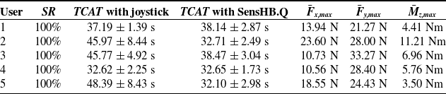
Experimental test results with MoviWE.Q: success rate (SR), task-completion average time (TCAT) and standard deviation with the joystick and with SensHB.Q, and the averages of the maximum absolute values of
 $F_{x}$
,
 $F_{y}$
, and
 $M_{z}$
recorded during the tests (respectively,
 $\bar {F}_{x,max}$
,
 $\bar {F}_{y,max}$
,
 $\bar {M}_{z,max}$
).
User n
 $^\circ$
1, experimental test no. 1 with SensHB.Q mounted on MoviWE.Q: (a) top view map of the experimental setup with the obtained trajectory; (b) photo of the setup from camera A; (c) photo of the setup from camera B.

The results of the experiments conducted with the MoviWE.Q wheelchair are summarized in Table II. The table reports the success rate (
 $SR$
), the task-completion average time (
 $TCAT$
) for both the joystick and the SensHB.Q interface, and the average maximum absolute values of the recorded force and torque components:
 $\bar {F}{x,\text{max}}$
,
 $\bar {F}{y,\text{max}}$
, and
 $\bar {M}_{z,\text{max}}$
. For each participant, an individual trial
 $i$
is considered successful (
 $SR_i = 100\%$
) if the driver is able to complete the trajectory without colliding with any of the obstacles on the track; otherwise, the trial is marked as unsuccessful (
 $SR_i = 0\%$
). After completing all five trials, the overall success rate
 $SR$
is computed as the average of the five individual success scores, that is,
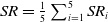 $SR = \frac {1}{5} \sum _{i=1}^{5} SR_i$
.
All users successfully completed the task with a
 $100\%$
success rate using both the joystick and the force-sensitive interface, SensHB.Q. The average task-completion time across all tries was
 $42.12 \pm 7.97$
s with the joystick and
 $34.13 \pm 3.41$
s with SensHB.Q. This indicates that, on average, users were able to complete the task more quickly and with more consistent results with the force-sensitive interface compared to the joystick.
Regarding the magnitude of the input forces and torque required to control the wheelchair, the average maximum force along the
 $x$
-axis of the body frame
 $b$
was
 $15.48$
N, along the
 $y$
-axis was
 $27.07$
N, and the average maximum torque around the
 $z$
-axis was
 $6.37$
Nm. Considering the total weight of the system, these required inputs are relatively low and are expected to be within the physical capabilities of most users. Moreover, if a driver is unable to apply such levels of force or torque comfortably, the parameters of the sliding-object model can be adjusted to tailor the required force range to the user’s preferences.
As an example, the results of the first test performed with SensHB.Q by the first participant are reported and discussed in the following paragraph. The obtained trajectory is shown in Fig. 7(a), while Fig. 8 presents the measured wrench components (input variables of SensHB.Q) and the generated reference velocity twist components (output of SensHB.Q). The trajectory was derived by integrating the feedback of the wheelchair’s velocity twist over time. The velocity twist feedback is computed using the forward kinematic relationship (10) and the measured steering angles
 $\delta _i$
and wheel velocities
 $\dot {\theta }_i$
. This odometry-based approach is known to be affected by position drift, and its accuracy degrades on uneven or slippery terrain due to wheel slippage [Reference Mohamed, Haghbayan, Westerlund, Heikkonen, Tenhunen and Plosila21]. Nonetheless, in this case, the data acquisition period is relatively short, and the ground surface is flat. Therefore, the computed velocity twist can be considered a reliable approximation of the actual wheelchair velocities during the test.
User n
 $^\circ$
1, experimental test n
 $^\circ$
1 with SensHB.Q mounted on MoviWE.Q: (a) measured wrench components (input variables of SensHB.Q), (b) the computed reference velocity twist (output of SensHB.Q).

User n
 $^\circ$
1, reference velocity twist components during the experimental test n
 $^\circ$
1 with the three-axis joystick mounted on MoviWE.Q.

Figure 9 reports the velocity twist reference generated by user n
 $^\circ$
1 using the joystick mounted on the wheelchair during the first trial. By comparing the velocity twist reference produced with SensHB.Q (Fig. 8(b)) and that obtained with the three-axis joystick (Fig. 9), it is evident that the driver was able to generate smoother velocity profiles using the force-sensitive interface.
The velocity references shown in Fig. 9 exhibit noticeable acceleration and deceleration phases. This phenomenon is associated with the user interaction dynamics: when the driver intends to move in a particular direction, the joystick is tilted accordingly. As the system begins to move, the base of the joystick – being attached to the wheelchair – moves with it, while the driver, who is not rigidly attached to the chair, experiences relative motion. This motion affects the tilt angle of the joystick, as the driver must continuously adjust to compensate for the relative motion between themselves and the joystick base. In other words, because the driver is not fixed to the joystick’s base, maintaining a consistent tilt angle becomes challenging. This observation supports the initial assumption presented in the fifth paragraph of the Introduction, highlighting a key advantage of the proposed force-sensitive interface.
4.2. Agrimaro.Q: experimental tests
At last, the force–torque sensitive interface SensHB.Q was tested with the Agrimaro.Q omnidirectional rover for precision agriculture. These tests were conducted to validate that SensHB.Q can be adopted across different application fields and integrated with various types of motorized systems.
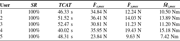
As in the experiments with MoviWE.Q, participants were instructed to move the agricultural rover from a designated start position to an end position, as illustrated in Fig. 10(a). Figures 10(b) and (c) show the experimental setup and the rover equipped with the SensHB.Q interface mounted on its frame. Five people participated, and each driver completed the task five times. The results of the experiments conducted with Agrimaro.Q are summarized in Table III.
The nomenclature adopted is the same as in the tests with MoviWE.Q in Section 4.1, and thus, definitions are not repeated here. Comparing the results in Table III with those in Table II, it can be observed that the force and torque levels are comparable. Therefore, it can be stated that the overall physical effort required to operate the system remains similar, even though the weight and size of the two motorized systems differ significantly.
As an example, the results of the first test performed with SensHB.Q by the first participant are reported and discussed in the following paragraph. The resulting trajectory is shown in Fig. 10(a), while Fig. 11 presents the measured wrench components (input variables of SensHB.Q) and the corresponding generated reference velocity twist components (output of SensHB.Q). As expected, the results are consistent with those obtained using the motorized wheelchair MoviWE.Q, confirming the repeatability and adaptability of the interface across different platforms.
Experimental test results with Agrimaro.Q: success rate (SR), task-completion average time (TCAT) with SensHB.Q, and the averages of the maximum absolute values of
 $F_{x}$
,
 $F_{y}$
, and
 $M_{z}$
recorded during the tests (respectively,
 $\bar {F}_{x,max}$
,
 $\bar {F}_{y,max}$
,
 $\bar {M}_{z,max}$
).

Validation test with Agrimaro.Q: (a) top view map of the experimental setup with the obtained trajectory of test no.1; (b) photo of the setup from camera A; (c) photo of the setup from camera B.

Validation test no. 1 with Agrimaro.Q: (a) measured wrench components (input variables of SensHB.Q), (b) the computed reference velocity twist (output of SensHB.Q).

5. Conclusion
This paper presents the development of SensHB.Q, a drive interface for motorized systems such as electric-powered wheelchairs, trolleys, mobile robots, and lifting devices. The interface is based on an articulated six-bar mechanism constrained by three single-axis load cells. In addition, contact sensors – such as capacitive switches – are integrated into the ergonomic handles to detect whether the user is gripping the handlebar correctly. The forces and torques applied by the user are measured and converted into velocity commands for the motorized system through a transfer function based on a simple dynamic model of an object sliding on a plane with Coulomb-like friction.
To evaluate the effectiveness of SensHB.Q, experimental tests were conducted using two platforms: the MoviWE.Q electric-powered wheelchair and the Agrimaro.Q rover for precision agriculture in greenhouse environments. Both systems are research prototypes developed at Politecnico di Torino and feature swerve-drive motorized wheels. The paper includes a summary of the kinematic models used for both platforms to derive the relationship between the velocity twist and the actuation variables.
During the experiments, drivers used SensHB.Q to move each system from a designated start pose to an end pose. In all trials, the drivers were able to complete the task successfully, demonstrating the feasibility and effectiveness of the proposed force-sensitive interface.
Future work includes further investigation about the parameter tuning of the transfer function to optimize the user experience. Finally, the adaptability of the interface should be validated on commercial motorized platforms to confirm its broader applicability.
Author contributions
LTa, AB, and FA conceived and designed the study. LTa, AB, FA, and LTo conducted data gathering. LTa and GC derived the kinematic model. LTa, FA, GC, and AB wrote the article, and SD, LTo, LB, and GQ revised it.
Financial support
This work was supported by the National Center for the Development of New Technologies in Agriculture (Agritech). https://agritechcenter.it/ (accessed on 12 Feb. 2025).
Conflicts of interest
The authors declare no conflicts of interest exist.
Ethical approval
Not applicable.