I. INTRODUCTION
Power divider is one of the fundamental devices in microwave and millimeter-wave circuits such as mixers, power amplifiers, and phase-array antennas [Reference Wu, Liu, Xue, Li and Yu1–Reference Pozar3]. Microstrip transmission lines have been widely used in power dividers because of compatibility with planar circuits and simple manufacturing process. But in these structures, the electromagnetic leakage and coupling are serious problems at high frequencies that limit their applications.
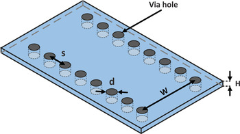
Conventional waveguide power dividers have the advantages of high Q-factor and low loss capacity [Reference Chen and Wu4, Reference Rui, Mengjia, Houjun, Zhen and Pei5]. But, these structures suffer from problems of high cost, bulky volume, and difficult integration with planar circuits [Reference Hao, Hong, Li, Zhang and Wu6]. Recently, substrate integrated waveguide (SIW) structure is introduced [Reference Uchimura, Takenoshita and Fujii7, Reference Yan, Hong, Wu and Cui8]. The SIW is configured by metallic via holes, as shown in Fig. 1. This structure has the benefits of the low loss, low cost, high Q-factor, and easy integration with planar circuits [Reference Bozzi, Georgiadis and Wu9]. The size of the SIW is relatively large. The half mode substrate integrated waveguide (HMSIW) can be considered by separating the SIW along the propagation direction, which is an equivalent magnetic wall [Reference Hong10]. By this work, compared with the SIW, the size of the structure is reduced by nearly 50%.
Configuration of a SIW structure.

Several power dividers based on SIW and HMSIW have been investigated [Reference Smith and Abhari11–Reference Li and Dou20]. In [Reference Zou, Tong and Yu14], a Y-junction four-way power divider was reported. This power divider had the large insertion loss. The reported circuit in [Reference Rosenberg, Salehi, Bornemann and Mehrshahi16] had the large insertion loss and large phase imbalance. Among these SIW/HMSIW power dividers, two T-junction SIW power dividers with arbitrary power division ratio were introduced in [Reference Contreras and Peden19] and [Reference Li and Dou20]. But these power dividers had the disadvantages of the large insertion loss and big size because the T-junction nature is comparatively large size.
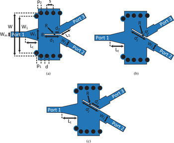
In this paper, a compact power divider based on HMSIW with an arbitrary power dividing ratio is proposed. Three circuits with power division ratios of 1:1, 1:4, and 1:8 are presented. These structures consist of an SIW transition, two bisected HMSIW transitions by a gap, an SIW-to-microstrip transition in the input port at the left side, two microstrip feed lines in the output ports at the right side, and a resistor between the two HMSIW transitions. In the circuit of the equal power divider, this resistor is just added to achieve the isolation between the output ports. But their value and location, the angle of the gap with the propagation direction, and the length of the gap are the parameters of the power management in the two other circuits. Four graphs are plotted using a three-dimensional electromagnetic (3D EM) simulator to graphically determine the introduced parameters. Figure 2 shows the configuration of these circuits. Moreover, the used SIW-to-microstrip transition is introduced in [Reference Kordiboroujeni and Bornemann21]. It features two vias, which have the same diameter as the SIW vias and are located symmetrically at both sides of the microstrip taper. These designs are simulated using the 3D EM simulator and fabricated on a Rogers RO4003C substrate. The results show a good agreement between the simulated and measured results. The measured results display these circuits (1:1, 1:4, and 1:8) have the bandwidths of 70, 36, and 40%, respectively.
Configuration of the proposed structures: (a) Δout = 0 dB, (b) Δout = 6 dB, and (c) Δout = 9 dB.

II. DESIGN PROCEDURE
A) SIW and HMSIW design
As shown in Fig. 2(a), one SIW transition is used and two HMSIW transitions are separated with a gap between them. The TE 10 is the dominant mode of the SIW structure. The cutoff frequency is obtained by [Reference Pozar3]:
 $${f_{cmn}} = \displaystyle{c \over {2\pi \sqrt {{\mu _r}{\varepsilon _r}}}} \sqrt {{{\left( {\displaystyle{{m\pi} \over {{W_{eff}}}}} \right)}^2} + {{\left( {\displaystyle{{n\pi} \over h}} \right)}^2}}. $$
In this case, the cutoff frequency is the same as conventional rectangular waveguide. In (1), m and n are the mode indexes, c is the velocity of light in the free space, ε r is the relative permittivity of the substrate, μ r is the relative permeability of the substrate, h refers to the height, and W eff refers to the equivalent width of the SIW, which is equal to [Reference Xu and Wu22]:
 $${W_{eff}} = W - 1.08.\displaystyle{{{d^2}} \over s} + 0.1.\displaystyle{{{d^2}} \over W}.$$
In (2), d refers to the diameter of the vias, s is their longitudinal spacing, and W displays the transverse spacing of the two vias that are located at both sides of the SIW. In this structure, the transverse magnetic (TM) modes cannot be guided due to the dielectric gaps created by the via separations [Reference Rayas-Sánchez and Gutierrez-Ayala23]. For the better performance of the circuit, d and s are limited as follows [Reference Wu, Deslandes and Cassivi24]:
 $$\displaystyle{s \over d} \le 2.$$
B) SIW-to-microstrip transition and microstrip feed lines design
In the input, a microstrip-to-SIW transition is used based on [Reference Kordiboroujeni and Bornemann21]. After designing the microstrip and SIW parameters, the taper-via transition parameters can be calculated as [Reference Kordiboroujeni and Bornemann21]:
 $${L_t} = 0.2368{\lambda _g}_{MS}, $$
 $${W_t} = {W_m} + 0.1547W,$$
 $${p_1} = 0.6561s,$$
 $${W_1} = 0.8556W.$$
λ g MS is the guided wavelength of the microstrip line calculated at the center frequency
 $${\lambda _g}_{MS} = \displaystyle{{{\lambda_{go}}} \over {\sqrt {{\varepsilon _{reff}}}}}. $$
In (8), ε reff refers to the effective dielectric constant of the microstrip line and λ g0 refers to the wavelength in free space. In the output, two microstrip feed lines are used. After designing the structure with 50 Ω microstrip lines, by tuning the parameters of the microstrip feed lines (W 2 and L 2), excellent impedance matching can be achieved.
C) Determining R, θ, d 1, and d 2
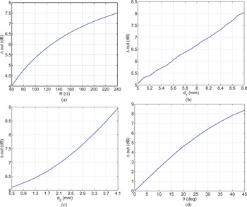
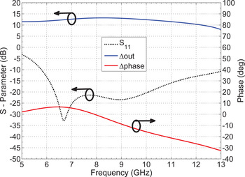
In this paper, the power management is realized by varying the value (R) and location of the resistor (d 2), the angle of the gap with the propagation direction (θ), and the length of the gap (d 1). To adjust the power division ratio, the value of θ is main parameter. If this parameter is equal to zero, then Δout = 0 dB, and the parameters of R, d 1, and d 2 have no effect on the power management. In the presented equal power divider, the used resistor is attached between two HMSIW transitions to improve the isolation and return loss of the output ports. The parameters of R, d 1, and d 2 are arisen by increasing the value of θ. Figure 3 shows the values of Δout versus different R, θ, d 1, and d 2. This figure is obtained by changing the values of the introduced parameters. As shown in Fig. 3, the power difference between the output ports can be increased by increasing R, θ, d 1, and d 2. From Fig. 3(d), it can be concluded that the proposed structure can obtain the high power division ratio. Furthermore, by increasing the values of R, d 1, and d 2, the value of Δout can vary in a wider range (from 1:1 to 1:16). In order to prove it, an unequal power divider with Δout = 12 dB is designed. Figure 4 shows the simulated results of the unequal power divider with Δout = 12 dB.
Values of Δout versus different: (a) R when θ = 30°, d 1 = 5.83 mm, and d 2 = 1.21 mm, (b) d 1 when R = 150 Ω, θ = 30°, and d 2 = 1.21 mm, (c) d 2 when R = 150 Ω, θ = 30°, and d 1 = 5.83 mm, (d) θ when R = 150 Ω, d 1 = 5.83 mm, and d 2 = 1.21 mm.

Results of the compact HMSIW power divider with Δout = 12 dB (θ = 45°, R = 156 Ω, d 1 = 6.75 mm, and d 2 = 3.57 mm).

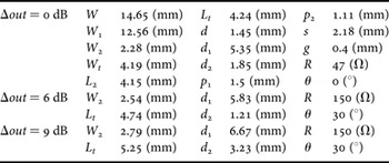
Moreover, Table 1 displays the parameters of the proposed structures shown in Fig. 2.
Parameters of the proposed structures.

III. SIMULATED AND MEASURED RESULTS
Three compact HMSIW power dividers with power division ratios of 1:1, 1:4, and 1:8 have been designed and fabricated on a single layer Rogers RO4003C substrate with a thickness, relative permittivity, and loss tangent of 0.8128 mm, 3.55, and 0.0027, respectively.
A) Compact HMSIW power divider with Δout = 0 dB
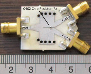
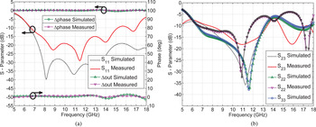
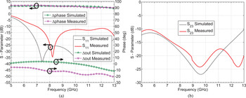
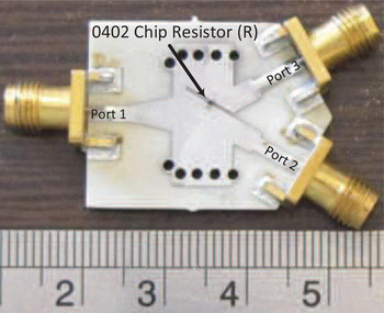
In the equal power divider, the measured results illustrate the return loss is >12.5 dB for the fractional bandwidth of 70% (7.08–14.77 GHz). Moreover, Δout is <0.3 dB and Δphase is <2°. But the isolation between output ports and the return loss of the output ports are >10 dB for the fractional bandwidth of 43% (7.67–11.87 GHz). The photograph of the fabricated equal power divider is shown in Fig. 5. Figures 6(a) and 6(b) depict the simulated and measured results of the proposed structure.
Photograph of the compact HMSIW power divider with Δout = 0 dB.

Simulated and measured results of the compact HMSIW power divider with Δout = 0 dB: (a) S 11, Δout, and Δphase, (b) isolation (S 23) and the return loss of the output ports (S 22 and S 33).

B) Compact HMSIW power divider with Δout = 6 dB
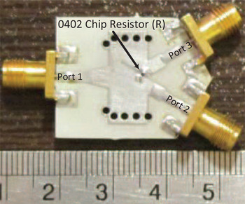
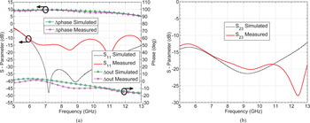
In the unequal power divider with Δout = 6 dB, the measured fractional bandwidth is 36% (7.59–10.88 GHz), Δout is <Δout ± 12%, and Δphase is <18° when the return loss is better than 12.5 dB. The photograph of the fabricated unequal power divider with Δout = 6 dB is shown in Fig. 7. Figures 8(a) and 8(b) depict the simulated and measured results of the proposed structure.
Photograph of the compact HMSIW power divider with Δout = 6 dB.

Simulated and measured results of the compact HMSIW power divider with Δout = 6 dB: (a) S 11, Δout, and Δphase, (b) isolation (S 23).

C) Compact HMSIW power divider with Δout = 9 dB
In the unequal power divider with Δout = 9 dB, the measured fractional bandwidth is 40% (6.18–9.25 GHz), Δout is <
 $\Delta out \pm 10\% $
, and Δphase is <10° when the return loss is better than 12.5 dB. The photograph of the fabricated unequal power divider with Δout = 9 dB is shown in Fig. 9. Figures 10(a) and 10(b) depict the simulated and measured results of the proposed structure. It should be noted here that the bandwidth is limited by both input matching and Δout variations.
Photograph of the compact HMSIW power divider with Δout = 9 dB.

Simulated and measured results of the compact HMSIW power divider with Δout = 9 dB: (a) S 11, Δout, and Δphase, (b) isolation (S 23).

The proposed structures (1:1, 1:4, and 1:8) are compact and have the overall sizes of
 $1.13 \times 1.04\lambda _g^2 $
,
 $0.96 \times 0.91\lambda _g^2 $
, and
 $0.81 \times 0.78\lambda _g^2 $
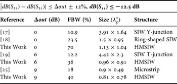
, respectively. This indicates that the proposed structures are a good candidate for compact HMSIW power divider with arbitrary power dividing ratio. Some slight differences between the measured and simulated results is mainly caused by the insertion loss of sub-miniature-A (SMA) connectors, fabrication errors, and the tolerance of the dielectric constant. In Table 2, a comparison between this work and other works is summarized.
Comparison with other works.

FBW: fractional bandwidth.
IV. CONCLUSION
In this paper, a compact HMSIW power divider with an arbitrary power dividing ratio has been presented. Compared with the previously introduced structure, this unequal power divider can be widely used in millimeter-wave systems and microwave because of its simple and compactness in size.
 Ali-Reza Moznebi was born in Sirjan, Iran, in 1990. He received the B.S. degree in Electrical Engineering from O.T.F. University, Fars, Iran, in 2013, and the M.S. degree in Electrical Engineering from the Shahid Bahonar University of Kerman, Kerman, Iran, in 2016. He is currently working as a post-graduate scholar at the Department of Electrical Engineering (Shahid Bahonar University of Kerman). His research interests include microwave/millimeter-wave power-dividing technology and microwave/millimeter-wave devices, circuits, and systems.
 Kambiz Afrooz was born in Baft, Iran, in 1983. He received the B.Sc. degree from the Shahid Bahonar University of Kerman, Kerman, Iran, in 2005, the M.Sc. and Ph.D. degrees from the Amirkabir University of Technology (Tehran Polytechnic), Tehran, Iran, in 2007 and 2012, respectively, all in Electrical Engineering. In May 2011, he joined the CIMITEC group, University Autonoma de Barcelona (UAB), Barcelona, Spain, as a Visiting Student. He is currently an Assistant professor with the Electrical Engineering Department, Shahid Bahonar University of Kerman, Kerman, Iran. His research interests include computer-aided design of active and passive microwave devices and circuits, computational electromagnetic, modeling and simulation of high-speed interconnects, metamaterial transmission lines, and substrate integrated waveguide structures. He is also the recipient of the Electrical Engineering Department Outstanding Student Award in 2007.