I. INTRODUCTION
There are very few material systems that combine low thermal expansion with high stiffness over an appreciable temperature range.Reference Steeves, dos Santos e Lucato, He, Antinucci, Hutchinson and Evans1 The vast majority of materials exhibit dimensional instability when subject to temperature change and expand appreciably when heated. While it is common for materials to exhibit dimensional instability of this type, there are multitudes of situations where uneven thermal loading, or the mechanical mating of dissimilar materials, leads to design limiting strains and/or stresses as a result. When heat is introduced, the thermal excitation of constituent molecules and atoms causes their average distance to increase with temperature, resulting in a volumetric dilatation. In applications such as hypersonic vehicles and space mirrors, where large thermal fluctuations and/or uneven thermal loading are the norm, the thermal expansion and dimensional instability of parts can become a significant issue. In these cases, there can be large nonuniform thermal strains across a structure that can, if not checked, lead to nonoperation or failure. Space mirrors must not warp when a portion of the structure is exposed to the sun and substantially hotter than unexposed regions. In hypersonic vehicles, extreme thermal loading of the external surface, due to air friction, can cause large stresses and strains to occur. The interior of these vehicles is necessarily cool—as they contain systems related to electronics, fuel, or passengers—that can lead to large thermal stresses.
Thermal strains can be mitigated on the molecular scale through chemistry, generally in complex structures, and only in a very limited number of materials. A variety of mechanisms have been proposed, including the rotation of rigid sublattices, e.g., ZrW2O8Reference Bridges, Keiber, Juhas, Billinge, Sutton, Wilde and Kowach2 which can accommodate the extension of atomic bonds in a manner that does not produce a volumetric change. Typical aerospace materials, however, such as steels, and alloys made from titanium, aluminum, magnesium, nickel, and cobalt, the latter two being high-temperature alloys, all expand appreciably with temperature. There is, notably, one steel that has a near zero thermal expansion. Invar is used, for example, in watch making, for its dimensional stability; however, this property only exists over a moderate temperature range, approximately 0–100 °C. Another strategy to achieve zero, low, or even negative thermal expansion, is to combine two or more materials with dissimilar coefficients of thermal expansion (CTE) into low density configurations, where, when heat is added, the material expands locally into void space to accommodate thermal strains.Reference Steeves, dos Santos e Lucato, He, Antinucci, Hutchinson and Evans1,Reference Berger, Mercer, McMeeking and Evans3 This class of materials is known as tailorable thermal expansion lattices, and a number of designs have been proposed.Reference Lehman and Lakes4–Reference Rhein, Novak, Levi and Pollock14
In tailorable thermal expansion lattices, two materials with substantially different CTE are arranged in space in such a manner that the net thermal expansion (that of particular lattice points) is significantly different from the CTE obtained by the rule of mixtures, αRM. Depending on the materials and geometry selected, zero and negative thermal expansions can be exhibited from constituent materials that individually have high CTE. This facilitates the use of materials in situations where, previously, their thermal expansion properties were prohibitive. For example, ductile refractory alloys are desirable for use in load bearing thermal protection systems for hypersonic aircraftReference Rhein, Novak, Levi and Pollock14; however, their relatively large thermal expansion coefficients prohibit their use in more traditional systems; low CTE lattices can enable such systems that combine low CTE, structural robustness, and high operating temperatures. It should be noted, however, that thermal strains are accommodated by the rotation of material into void space, necessitating low relative density configurations that have stiffnesses and strengths that are only a small fraction of the constituent materials. Moreover, the issue of mismatched thermal expansion is still present, albeit at a smaller scale. However, these thermal strains and stresses are not necessarily design limiting in this setting, and the resulting plasticity can occur in a limited and temporary fashion as shakedown.Reference Steeves, Mercer, Antinucci, He and Evans15
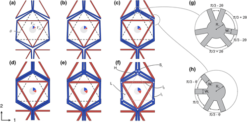
One particular lattice geometry is capable of achieving the theoretical bounds for biaxial stiffness.Reference Steeves, dos Santos e Lucato, He, Antinucci, Hutchinson and Evans1 This design, known as the UCSB lattice, has a triangular bimaterial assembly of beams as a base unit. These units are arranged in 3-fold symmetry to form the types of unit cells shown in Fig. 1. For a more detailed description of the geometry and mechanics, see our previous work.Reference Berger, Mercer, McMeeking and Evans3 The UCSB lattice has received substantial attention due to its near optimal stiffness.Reference Steeves, dos Santos e Lucato, He, Antinucci, Hutchinson and Evans1,Reference Jefferson, Parthasarathy and Kerans7,Reference Toropova and Steeves9,Reference Steeves, Mercer, Antinucci, He and Evans15–Reference Toropova and Steeves18 Structures have been fabricated out of titanium and aluminum alloys, both in pin-jointedReference Steeves, Mercer, Antinucci, He and Evans15 and bonded joint configurationsReference Berger, Mercer, McMeeking and Evans3 and found to have thermal responses well predicted by models. To convert the complex multipart pin-jointed structure into a simpler bonded configuration, more amenable to manufacture, some modifications to the geometry are necessary. Inter-unit-cell spacers, to avoid overlap of neighboring unit cells, are necessary to achieve the desired thermal expansion behavior.Reference Berger, Mercer, McMeeking and Evans3 Steeves et al.Reference Steeves and Evans16 optimized the stiffness of sandwich panel thermal protection systems that utilized the lattice as the face sheet material on the hot side to produce lightweight designs. Thin bonded unit cells, between 50 and 250 μm through thickness, were modeled and fabricated by Gdoutos, Shapiro, and DaraioReference Gdoutos, Shapiro and Daraio19 to assess out of plane deformations that resulted from bonding constituents cut from sheets of the material that are then welded together transversely. High temperature alloys have been used to fabricate unit cells to assess the challenges in fabricating and applying thermal barrier coatings to such systems.Reference Rhein, Novak, Levi and Pollock14 In the investigation of a different bimaterial lattice,Reference Jefferson, Parthasarathy and Kerans7 it was shown that the UCSB lattice, in a pin-jointed configuration, performs at the theoretical bound over a wide range of relative densities and effective CTEs and is better than the other designs considered. The UCSB lattice has been investigated for its ability to have in-plane anisotropic thermal expansion behaviorReference Toropova and Steeves18 and for its potential to form thermal actuators.Reference Steeves and Toropova17 In Ref. Reference Toropova and Steeves18, the UCSB lattice design was extended from in-plane isotropic form to include in-plane anisotropic thermal expansion, by breaking the in-plane 3-fold symmetry, with an aim of developing structures that bridge dissimilar materials without developing thermal stresses between them.Reference Toropova and Steeves9 We seek to extend this body of work by assessing the strength of this system by examining the mechanical performance of a set of lattices designed to have optimum stiffness and zero CTE, and comparing their behavior to theoretical upper bounds. Bonded lattices are much simpler from the standpoint of fabrication and scalability and are a step toward the development of quasi-bulk materials with novel thermomechanical properties.
FE unit cell geometry for lattices designed to have zero thermal expansion,  $\bar{\alpha } = 0.0$ (ppm/K), with skew angles 27°–32° in 1° increments [(a) through (f)], having the material properties listed for System-1. Material volume fractions are shown in inset pie diagrams, with the grey color representing the fraction not occupied by the material. The relative density increases while the member aspect ratio decreases, both monotonically, with increasing skew angle. The ratio of the low CTE (blue) and high CTE (red) constituents varies only slightly, as it is mostly determined by the ratio of Young’s moduli of the constituents, which is the same in all models. The dashed lines show the fundamental connectivity of the lattice, which is triangular. The spacing between lattices is designed to accommodate a thermal excursion of ∆T = 250 K. (models n.t.s); in all cases L = 50 mm. The geometric approximations of the joints used in the calculation of CTE are shown in (g) and (h). The radius of the joints is exaggerated to illustrate these geometric entities.

In our analysis, there is no absolute length scale, other than that of the constituent material and its microstructural features. As a result, the millimeter scale geometries studied in this and previous studies are not necessarily representative of potential applications. There are a wide variety of fabrication methods, including microscale techniques,Reference Bauer, Meza, Schaedler, Schwaiger, Zheng and Valdevit20 that could potentially be utilized to produce mesoscale metamaterials that possess a tailorable CTE.
In our previous work, we developed an analytical model, based upon beam theory, for the thermal expansion of the UCSB lattice with bonded joints. In this work, we have incorporated into the model, a system of equations that can specify a complete bonded lattice geometry, including the spacer element. Using this system, coupled with a beam element-based finite element (FE) model, we identify optimal lattice designs that maximize biaxial stiffness for a set of constituent materials, subject to the constraint of a prescribed thermal expansion coefficient,  $\bar{\alpha }$, that is effectively zero. A thermal excursion is prescribed, ΔT = 250 K, that is comparable to previous experimentsReference Berger, Mercer, McMeeking and Evans3,Reference Steeves, Mercer, Antinucci, He and Evans15 and large enough to produce substantial deformation and rotation of struts. The biaxial stiffness is the elastic ratio of the sum of the in-plane principal stresses applied to the lattice to the effective area change of the lattice. The behavior of the UCSB lattice is found to be isotropic in-plane. We analyze the structures produced from this method using a high-resolution three-dimensional (3-D) FE model to assess the predictions for thermal expansion, stiffness, and strength provided by the lower cost approaches. The high-resolution models are able to capture detailed features of failure and localization during both thermal and mechanical loading. It should be noted, while 3-D continuum elements are used in these simulations, the results generated in this study are limited to deformation modes that are two-dimensional in nature. Lattice designs that are relatively thin have the opportunity to buckle and otherwise deform out of planeReference Berger, Mercer, McMeeking and Evans3; however, as we will discuss, this is not a primary concern. Using the low cost beam-based FE model, we construct yield surfaces for elastic buckling and perfectly plastic yielding and compare these results to 3-D FE models to assess the strength of lattice designs. We use notional materials that are generally representative of a titanium–aluminum system, with CTEs α1 = 10 ppm/K and α2 = 25 ppm/K, respectively, but having equal elastic moduli and perfectly plastic yield stress; this is carried out to simplify the analysis and lay the foundation for a future parametric materials selection study.
The model is found to produce lattice designs with CTE that are well predicted by the low-cost design algorithm. Our analysis shows that bonded lattices are found to have a temperature-dependent CTE that stems from changes in skew angle θ (see Fig. 1) and member length, over a somewhat moderate thermal excursion of ΔT = 250 K. The onset of plasticity, which initializes and occurs at the bimaterial interfaces, exacerbates the temperature dependence of the CTE. In some cases, the expansion of members causes neighboring unit cells to contact (i.e., the lattice densifies), dramatically and instantaneously driving the CTE toward that of the Type-1 material—the continuous, low CTE, phase. Densification also increases the modulus and ultimate strength dramatically, which may be a useful feature in some applications if addressed appropriately through design. The biaxial stiffnesses of these structures are plotted along with theoretical bounds and such stiffnesses are found to inherit the near optimal characteristics of the parent pin-jointed structure, suffering only a small penalty for the bonding of the joints. Large stress concentrations, associated with the nodes where slender members meet, result in lattice effective strengths that are only a few percent of the constituent’s yield strength. Variations in Poisson’s ratio, somewhat independent of stiffness and CTE, creates an opportunity to design functionally graded and auxetic structures that exhibit dimensional stability or engineered straining under combinations of thermal and mechanical loading.
II. METHODOLOGY
The thermomechanical response of the UCSB lattice, with bonded joints and spacers between unit cells, is documented in Ref. Reference Berger, Mercer, McMeeking and Evans3, as is a full description of the geometry. To design lattices, we use the analytical beam theory model provided in Ref. Reference Berger, Mercer, McMeeking and Evans3 for thermal expansion to identify lattice geometries with the desired thermal expansion coefficient. This approach is coupled with a low-cost FE model that utilizes beam elements to calculate stiffness and strength and provides a computationally inexpensive method for searching design space. For any set of constituent materials and a desired lattice CTE,  $\bar{\alpha }$, a variety of designs exist, whose geometries vary in skew angle, member width, stiffness, strength, and density; throughout the bar notation is used to denote the effective properties of the lattice, and α is CTE. By contrast, the parent pin-jointed lattice has a CTE that only depends on the skew angle.Reference Steeves, dos Santos e Lucato, He, Antinucci, Hutchinson and Evans1 From a set of bonded lattice designs, composed of the same constituent materials and with identical
 $\bar{\alpha }$, we identify combinations of geometric parameters that store strain energy most efficiently and that have the highest biaxial stiffness. A high-resolution three-dimensional (3-D) FE model is used to verify and validate the results of the lower resolution approach and to identify the geometric features responsible for localization and failure. The low cost beam model is used to predict the onset of plasticity and elastic buckling, from which perfectly plastic yield surfaces are generated. The high-resolution 3-D FE models employ solid continuum elements and use a homogenization technique to extract the effective mechanical properties of lattice designs.
A. Modeling
Three modeling approaches are utilized. An analytical model, based upon beam-column theory, is used to predict lattice CTE.Reference Berger, Mercer, McMeeking and Evans3 A beam-element based FE model utilizes an Euler–Bernoulli beam theory formulation, having six degrees of freedom, two translational and one rotational, at each end of an element. Stretch of the element is permitted and accounted for in the formulation. Each lattice member is composed of a single element, and continuity of translation and rotation is imposed at each node of the lattice. The simple beam model is used to calculate limit surfaces for perfectly plastic yielding and elastic buckling in each member. The maximum stress in each member is assumed to occur at a point on the surface of a member and can be the result of both bending and axial deformations. A 3-D FE homogenization method is used to model stress distributions with high resolution and to identify the geometric features associated with stress concentration and localization. This homogenization approach is the same as was used in previous work,Reference Berger, Mercer, McMeeking and Evans3 which has been shown to accurately model both mechanical and thermal loading experiments. This 3-D FE scheme was developed within a broader investigative framework where a variety of loading and failure scenarios can be considered. However, the results in this study include only in plane failure modes. It is assumed that lattices are sufficiently thick as to avoid transverse deformations (which they are in this study), or that lattice nodes are attached to a neighboring structure, e.g., sandwich panel core,Reference Steeves and Evans16 which prevents transverse deformations; the latter case is the more likely scenario in practice. In previous research efforts, FE models used plane elementsReference Steeves, Mercer, Antinucci, He and Evans15 so that we refer to our simulations as 3-D to make a distinction.
To measure the stiffness of lattice designs, model geometries are subject to states of axial and biaxial macroscopic stress in the coordinate system shown in Fig. 1. Under these loading conditions, deformations are left–right symmetric so that members can be placed into pairs that experience equivalent stress states. There are then five distinct populations of members to consider when calculating failure—three Type-1 and two Type-2 groups. For each group, a perfectly plastic yield surface can be constructed using the beam FE model. These surfaces are combined to construct a perfectly plastic yield surface for the complete lattice geometry. Initial yield occurs from the superposition of bending and axial stresses in each member. We also calculate the elastic buckling load; however, such buckling loads are much higher than the loads associated with yielding due to the bending and stretching of members in most configurations except those with very slender members.
FE calculations with 3-D elements are performed using the commercial code Abaqus 6.14-3.21 This approach captures deformations transverse to the lattice plane, including the complex interaction of the bimaterial interfaces, across which there is a discontinuous change in material properties. We use 8-noded reduced integration elements for calculations involving plasticity (type C3D8R in Abaqus) and 20-noded 2nd order elements for purely elastic calculations (C3D20). The maximum stress in FE models is a function of the mesh resolution. A mesh sensitivity study was performed to ensure sufficient mesh resolutions and the convergence of the macroscopic stress versus strain response, and the models have been shown to accurately capture both thermal and compression experiments.Reference Berger, Mercer, McMeeking and Evans3 To capture bending deformations accurately, a minimum of eight linear elements is used through the thickness of a beam in the plane of the lattice in which bending takes place. Between three and eight elements are used in the direction transverse to the plane, with no model sensitivity quantitatively over this range. Bimaterial joints are modeled as perfectly bonded interfaces, with no opportunity for sliding.
Lattices have a characteristic dimension L = 50 mm so that the lattices in Fig. 1 have horizontal (1-direction) dimension L + H, and transverse dimension t = 4 mm, comparable to test specimens.Reference Berger, Mercer, McMeeking and Evans3,Reference Steeves, Mercer, Antinucci, He and Evans15 All other design parameters are output by the design scheme. The thickness is chosen to be greater than the maximum possible in plane member width, w max = 3.2 mm so that struts would preferentially buckle in the lattice plane. The maximum member width is chosen so that the smallest possible aspect ratio of struts is ∼8.
While no transverse effects were captured in this study so that switching to a 2D plane stress FE scheme would save computational time, all models are generated by a semi-automated scheme that produces 3D models. This was developed as a general-purpose system, capable of capturing both thermal and mechanical loading,Reference Berger, Mercer, McMeeking and Evans3,Reference Steeves, Mercer, Antinucci, He and Evans15 with the aim of consistency and ease of use, at the cost of lower computational efficiency. There is no requirement that the models used in this series of calculations be 3D. However, these lattices can be prone to transverse buckling under macroscopic compressive loads,Reference Berger, Mercer, McMeeking and Evans3 and in that case, 3D formulations are advantageous.
Three-dimensional FE models have periodic boundary conditions using a virtual node homogenization technique. Models are periodic only in the two in-plane directions parallel to the coordinate system of Fig. 1, which experience strain prescribed by a macroscopic strain tensor. A single node in the model is held fixed to prevent ridged body translations. The strains are imposed by tying the relative displacement of paired sets of boundary nodes to the displacement of “virtual nodes”, which are otherwise unattached to the model. The macroscopic strains are the displacements of these nodes and the macroscopic stresses are extracted through the “reaction forces” of these virtual nodes using the principle of virtual work. The method is described in detail in Ref. Reference Danielsson, Parks and Boyce22.
FE simulations use elastic–perfectly plastic material models. Nonlinear deformations are considered using the nlgeom flag (Abaqus). Contact is modeled using a “hard contact” algorithm. To capture some of the expected interactions between neighboring unit cells, analytical rigid surfaces are tied to the periodic nodes on the 1-direction normal faces to prevent material from extending outside of the rectangular RVE boundary. Since friction is highly material and system dependent, a moderate friction coefficient of µ = 0.6 was chosen for all surface interactions, and is representative of the static frictional interaction between two relatively low friction surfaces.
B. Theoretical bounds and performance parameters
To assess the performance of lattice designs, we plot their stiffness compared to theoretical limit. The Gibiansky–Torquato (GT) upper bound for in-plane isotropic multiphase composites limits the biaxial stiffness of these systems.Reference Gibiansky and Torquato23 As noted above, the UCSB lattice is isotropic elastically in-plane and exhibits in-plane isotropic thermal expansion. For each lattice geometry, we calculate the three-phase upper bound, which is a function of the properties of the two component materials, and a third void phase that has vanishing stiffness and density.
To compare material systems with different moduli, CTEs, and a variety of lattice geometries, some results are plotted in terms of the normalized properties,
 $${\bar{\alpha }_N} = {{\bar{\alpha }\left( {{V_{{\rm{f,1}}}} + {V_{{\rm{f,2}}}}} \right)} \over {{\alpha _1}{V_{{\rm{f,1}}}} + {\alpha _2}{V_{{\rm{f,2}}}}}}\quad ,$$
 $${\bar{K}_N} = {{\bar{K}} \over {{K_1}{V_{{\rm{f,1}}}} + {K_2}{V_{{\rm{f,2}}}}}}\quad ,$$
where  $\bar{\alpha }$ and
 $\bar{K}$ are the effective in-plane thermal expansion coefficient and bulk modulus, respectively, and the subscript N denotes the normalized measure. The normalizing quantities are respectively the rule of mixtures thermal expansion coefficient estimate and the Voigt elastic stiffness upper bound, where K i = E i/(2(1 − νi)) and V f,i are the 2-D bulk modulus and volume fraction of the Type-1 (lower thermal expansion) and Type-2 (higher thermal expansion) constituents, i = 1, 2, respectively. It should be noted that these designs are incapable of achieving the Voigt bound
 $\left( {{{\bar{K}}_N} = 1.0} \right)$; however, this normalized quantity facilitates comparison of different systems with different GT upper bounds (see Fig. 8).
C. Lattice design and materials selection
Lattice designs are constructed via an optimization scheme. A system of equations,
 $$\bar{E},\bar{K},\bar{\nu },{\bar{\sigma }_y} = F\left( {{\alpha _i},{E_i},{\nu _i},{h_i},{\sigma _i},\theta ,\Delta T,\bar{\alpha }} \right)\quad ,$$
along with a set of input parameters defines a lattice geometry and its properties; here, we use the bar notation to denote the effective properties of the lattice. The input parameters are the CTEs, αi, constituent materials’ Young’s moduli, E i, their Poisson’s ratios, νi, member widths, h i, tensile yield strengths, σi, lattice skew angle,Reference Berger, Mercer, McMeeking and Evans3 θ, the magnitude of the thermal excursion, ΔT, and the desired thermal expansion coefficient,  $\bar{\alpha }$. As noted above, Type-1 material is a continuous phase that has a relatively low CTE compared to the Type-2 material and provides a lattice design with low
 $\bar{\alpha }$.
There is a large design space, given the great number of material combinations that can be considered, but no obvious systematic way to search it exhaustively. We narrow the search to a set of notional materials, the properties of which are similar to the aluminum–titanium test system used in previous work.Reference Steeves, dos Santos e Lucato, He, Antinucci, Hutchinson and Evans1,Reference Berger, Mercer, McMeeking and Evans3,Reference Steeves, Mercer, Antinucci, He and Evans15 These notional materials are representative of a typical metal system whose CTEs generally range from 5 to 30 ppm/K. To simplify the analysis, the Young’s moduli are set equal, E 1 = E 2 = E, and the yield strains to a value of, εy,1 = εy,2 = 0.2%. We also set the Poisson ratios of the constituents to be equal, ν1 = ν2 = 0.3.
The effective thermal expansion of the spaced lattice design is,
 $$\bar{\alpha } = {{\Delta L + {\alpha _1}H} \over {L + H}}\quad ,$$
where L is the distance between lattice points, ΔL is its change in length for a unit thermal excursion [Eq. (17) in Ref. Reference Berger, Mercer, McMeeking and Evans3], and H is the dimension of the spacer (see Fig. 1). As noted above, the effective thermal expansion is isotropic in plane. The dimension of the spacer,
 $$H = \left\{ {\matrix{ {\max \left( {{{{h_1}\left( {\cos \theta - \sin \left( {{\pi \over 6} - \theta } \right)} \right)} \over {\cos \left( {2\theta - {\pi \over 6}} \right)}},\;2{l_1}\sin \left( {\theta - {\pi \over 6}} \right) + {h_1}\cos \left( {\theta - {\pi \over 6}} \right) + \varepsilon _2^t{l_2}} \right),\;\theta \lt {\pi / 6}} \cr {2{l_1}\sin \left( {\theta - {\pi \over 6}} \right) + {h_1}\cos \left( {\theta - {\pi \over 6}} \right) + \varepsilon _2^t{l_2},\;\theta \ge {\pi / 6}} \cr} } \right.\quad ,$$
is a function of the skew angle, the member widths, and the thermal strain of Type-2 members,  $\varepsilon _2^t = {\alpha _2}\Delta T$. This last term is needed to accommodate the axial thermal expansion of Type-2 members in lattices with large skew angles, to avoid contact between neighboring cells and the resulting densification.
The effective radii of the jointsReference Berger, Mercer, McMeeking and Evans3 are calculated as,
 $${R_1} = {{\sin \left( {{\pi \over 6} + \theta - \beta } \right){S_{\rm{r}}}} \over {\sin \left( {{{5\pi } \over 6} - \theta } \right)}} - {{{h_1}} \over 2}\tan \left( {{\pi \over 3} - \theta } \right)\quad ,$$
 $${R_2} = {{{h_1}} \over {2\sin \left( {{\pi \over 3} - \theta } \right)}} + {{{h_2}} \over {2\tan \left( {{\pi \over 3} - \theta } \right)}}\quad ,$$
where
 $$\beta = {\sin ^{ - 1}}\left( {{{\sin \left( {{{5\pi } \over 6} - \theta } \right)} \over {{S_{\rm{r}}}}}\left[ {{H \over {\sqrt 3 }} - {{{h_1}} \over {2\cos \left( {{\pi \over 3} - \theta } \right)}}} \right]} \right)\quad .$$
These replace Eqs. (18) and (19) in Ref. Reference Berger, Mercer, McMeeking and Evans3 as more accurate calculations of the joint geometry. The radius of the stiffener needed to transmit axial stresses in Type-1 members between neighboring unit cells without a geometric stress concentration is
 $${S_{\rm{r}}} = {{{h_1}} \over {2\cos \left( {{\pi \over 3} - \theta } \right)}} + {H \over {\sqrt 3 }}\quad .$$
With these equations, a complete lattice geometry, including spacer, is defined by the selection of h 1, h 2, ΔT, and θ for a set of constituent properties. By fixing the thermal load, ΔT, and the skew angle, θ, the desired effective coefficient of thermal expansion (CTE),  $\bar{\alpha }$, can be found by varying parameters h 1 and h 2. For a given set of constituents, there is then a variety of lattice designs that all have the desired CTE but vary in skew angle, relative density, stiffness, strength, Poisson’s ratio, and structural efficiency. We use these equations, along with models for structural stiffness and strength, to identify optimal lattice designs.
III. RESULTS AND DISCUSSION
A. Thermomechanical characterization of zero CTE metallic lattices
1. Lattice design
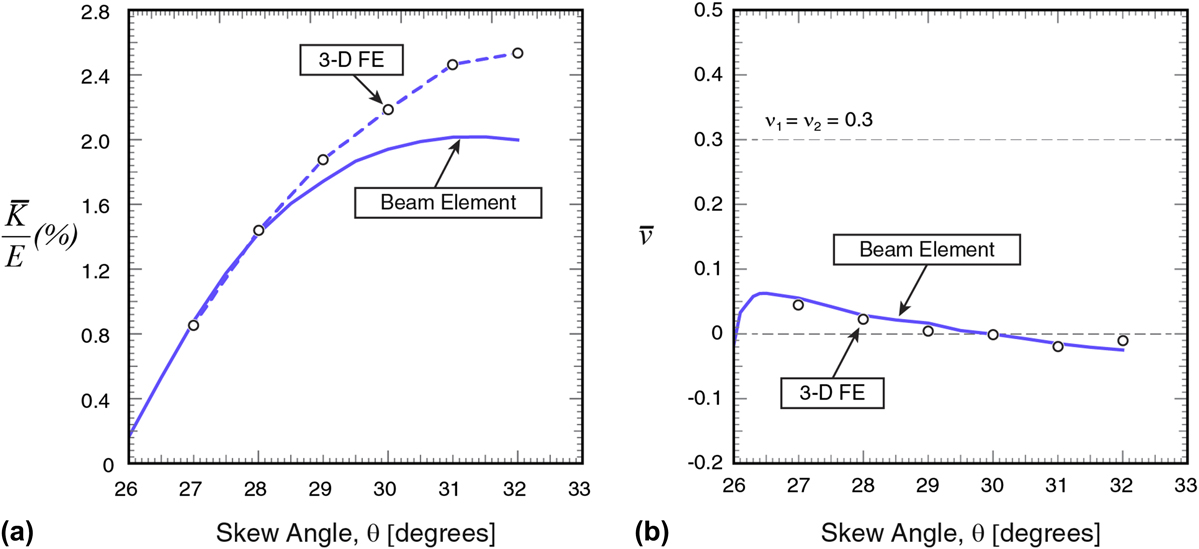
Using this set of equations [generically Eq. (3)], a series of lattices is designed to have a zero CTE,  $\bar{\alpha } = 0$. By selecting skew angles that vary from 26° to 32°, by increments of 1°, the geometries in Figs 1(a)–1(f) are generated. When the effective CTE for each lattice is computed by detailed FE analysis, it is found to be very close to, but not exactly equal to, zero. These skew angles span the range of performance that includes the peak biaxial stiffness predicted by our beam FE model as shown as a percentage of Young’s modulus in Fig. 2(a). Note that skew angles less than ∼27° are omitted because designs with skew angles below that level lead to very small effective biaxial moduli and very low relative densities due to the very slender nature of the struts in the lattice, as described further below. There is good agreement between the beam and 3-D FE models at low skew angles, where members are slender, and their behavior well predicted by beam theory. At high skew angles, members are relatively stocky so that the predictions of beam theory models are less accurate. Members joining together at nodes causes a reduction in their effective length, leading to further deviation from a beam theory prediction that does not account for this geometric effect.
Beam and 3-D FE predictions for biaxial stiffness (a) and Poisson’s ratio (b) for the lattices pictured in Fig. 1. The effective biaxial modulus is normalized by the elastic modulus of the constituents. 3-D FE results (circles) agree with beam element models best at lower relative densities and skew angles when members are slender. The beam theory model under-predicts the stiffness when the effective length of members, due to joint configurations, differs substantially from, and is shorter than, the joint-center to joint-center length. The reduction in effective length is due to the finite size of joints and spacers that results in overlap of members. This is most prominent at high skew angles when the dimension of the spacer is substantial. Predictions for Poisson’s ratio are in excellent agreement. Lattices have a near zero Poisson’s ratio that generally decreases with increasing skew angle.
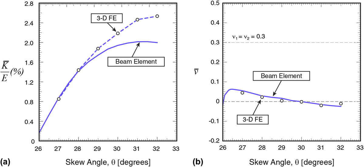
Although the beam FE model predicts a broad peak in biaxial stiffness in Fig. 2(a) at around, θ = 31°, the 3-D FE calculated stiffness increases monotonically over the range considered. The latter curve appears to be approaching a maximum that would lie at approximately 33° so that increasing the skew angle beyond 32° is unlikely to produce substantially stiffer designs. Moreover, lattices with skew angles in excess of ∼32° require excessively large interunit cell spacers to avoid overlap of perimeter members and are impractical to consider from a design standpoint. Large spacers become counterproductive to producing low CTE designs as the term α1H in Eq. (4) becomes relatively large, requiring substantially negative CTE primitive (i.e., pin-jointed) unit cells to achieve low net CTE. The agreement between the beam and 3-D FE models is excellent when members are slender at lower skew angles, permitting us to use the beam model as a tool to probe the property space of designs. The beam model has an insignificant computational and preprocessing cost compared to the 3-D FE homogenization models, making the parameter studies in this work computationally feasible.
In summary, our detailed FE results in Fig. 2(a) indicate that, for a zero thermal expansion lattice (the results in Fig. 2 are all for zero thermal expansion including the 3D FE results) with constituent materials having a similar Young’s modulus, the maximum biaxial stiffness achievable is approximately 2.5% of the Young’s modulus of the material used.
Poisson’s ratios for the same lattices that are the subject of Fig. 2(a) are calculated by both the beam and 3-D FE models and are found to be nearly identical from both computational methods and to be quite low over the entire range of skew angle considered [Fig. 2(b)]. The agreement of results from the two computational methods occurs despite discrepancies in effective member length that result in contrasts in biaxial modulus [Fig. 2(a)]. There is a monotonic and roughly linear decrease in the Poisson ratio over the range 27° ≲ θ ≲ 32°, with  $\bar{\nu } = 0.0$ when θ = 30.0°.
The background to our results for maximized biaxial stiffness can be understood more clearly by consideration of an analytical model developed in Ref. Reference Berger, Mercer, McMeeking and Evans3. In that context, we note that the lower limit on the skew angle for any set of materials is that of the pin-jointed lattice, and the thermal strain of a bonded-joint unit cell without spacer element is (rewritten from Ref. Reference Berger, Mercer, McMeeking and Evans3),
 $${{\Delta L} \over L} = {{\sqrt 3 p - qf\left( \theta \right)\sin \theta } \over {g\left( \theta \right)\cos \theta }} + {{12{I_1}f\left( \theta \right)\left[ {\sqrt 3 \cos \theta + \sin \theta \left( {3 + 2\beta {{{{\hat{L}}_2}} \over {{{\hat{L}}_1}}}} \right)} \right]\left[ {q - p} \right]} \over {{A_1}\hat{L}_1^2g\left( \theta \right)\cos \theta \left\{ {g{{\left( \theta \right)}^2} + {{12{I_1}} \over {{A_1}\hat{L}_1^2}}\left[ {2\beta {{{{\hat{L}}_2}} \over {{{\hat{L}}_1}}} + f{{\left( \theta \right)}^2}} \right]} \right\}}}\quad ,$$
where β = E 2w 2/E 1w 1 is the ratio of the axial stiffnesses of the Type-1 and -2 members, and
 $$f\left( \theta \right) = \cos \theta + \sqrt 3 \sin \theta \quad ,$$
 $$g\left( \theta \right) = \sqrt 3 \cos \theta - \sin \theta \quad ,$$
 $$p\left( {\theta ,{w_1},{w_2},{\alpha _1},{\alpha _2}} \right) = {1 \over {{L_1}}}\left( {\varepsilon _1^t{{\hat{L}}_1} + \hat{\varepsilon }_1^t{R_1} + \hat{\varepsilon }_2^t{R_2}} \right)\quad ,$$
 $$q\left( {\theta ,{w_1},{w_2},{\alpha _1},{\alpha _2}} \right) = {1 \over {{L_2}}}\left( {\varepsilon _2^t{{\hat{L}}_2} + 2\hat{\varepsilon }_2^t{R_2}} \right)\quad ,$$
are functions of the geometry and constituent properties. In these equations, L i are the node-to-node member lengths,  ${\hat{L}_i}$ are the effective member lengths that account for the size of the nodes (R 1 and R 2),
 $\varepsilon _i^t = {\alpha _i}\Delta T$ are the thermal strains of the constituent materials,
 $\hat{\varepsilon }_i^t = {\hat{\alpha }_i}\Delta T$ are the thermal strains in the bimaterial joints, having effective CTE
 ${\hat{\alpha }_i}$, and w i are the in-plane member widths, where i = 1, 2 for Type-1 and -2 members, respectively, or Type-1 and -2 joints (see Ref. Reference Berger, Mercer, McMeeking and Evans3 for details). The first term in Eq. (10) is the thermal strain of a unit cell due to changes in length of members, while the 2nd term is associated with their bending. Eqs. (13) and (14) for p and q quantify the axial thermal expansion of Type-1 and -2 members, respectively, and account for the differences in composition between the nodal and slender regions. For low CTE lattices, the thermal strain of Type-2 members is substantially larger than that of Type-1 members so that the quantity q − p > 0. The functions f and g are positive and are, respectively, monotonically increasing and decreasing functions of θ over the range of skew angles that it is practical to fabricate, 0 ≤ θ ≤ 32°. The functions p and q are positive and monotonically increase with θ. This is due to the fact that the length of the slender segments,
 ${\hat{L}_1}$ and
 ${\hat{L}_2}$, both increase with skew angle and dominate the behavior of Eqs. (13) and (14) due to the relatively small size of the nodal regions, i.e.,
 ${\hat{L}_1},{\hat{L}_2} \gg {R_1},{R_2}$.
In the case where the members have negligible bending stiffness, the 2nd term in Eq. (10) disappears, recovering the behavior of the pin-jointed parent structure.Reference Berger, Mercer, McMeeking and Evans3 When θ = 0, the 2nd term in the numerator,
 $$f\left( \theta \right)\sin \theta \;q\left( {\theta ,{A_1},{A_2},{\alpha _1},{\alpha _2}} \right) = 0\quad ,$$
and the CTE of the lattice is that of the Type-1 members,  $\bar{\alpha } = {\alpha _1}$. As θ increases, all three quantities, f(θ), sin θ, and q(θ, A 1, A 2, α1, α2), increase monotonically, while the denominator, g(θ) cos θ, decreases monotonically. The important result is that increasing the skew angle in the pin-jointed lattice always decreases the effective CTE.
Bonded lattices have a higher CTE than their parent pin-jointed geometries. The 2nd term in Eq. (10) is always positive so that bonding the joints, or increasing the width of Type-1 members in a bonded lattice, will always increase the effective CTE. This is what drives the designs with bonded joints to low densities at low skew angles and makes them unattractive due to their low stiffness. The pin-jointed effective CTE is only a function of skew angle for a given material system. Therefore, as the skew angle of a bonded lattice approaches that of the parent pin-jointed lattice, the struts must become thin to minimize the rotational stiffness of joints, to achieve the desired effective CTE. Bonding the joints, however, does open up a design space not achievable in the pin-jointed system, allowing a spectrum of designs, which vary in stiffness, strength, relative density, and Poisson ratio, to have the same effective CTE, made from the same constituent materials.
2. Tunable Poisson’s ratio
The Poisson ratio of the pin-jointed latticeReference Berger, Mercer, McMeeking and Evans3 can be written as
 $${\bar{\nu }_{{\rm{pin ‐ jointed}}}} = {{\beta f\left( \theta \right) + g\left( \theta \right)} \over {\beta m\left( \theta \right) + n\left( \theta \right)}}\quad ,$$
where β = E 2w 2/E 1w 1 is the ratio of the axial stiffnesses of the Type-1 and -2 members, and
 $$f\left( \theta \right) = 12\cos 2\theta - 6\left( {\cos 4\theta + 8\sqrt 3 \;\sin \theta \;{{\cos }^3}\;\theta } \right) + 12\quad ,$$
 $$g\left( \theta \right) = 3\;\cos \;3\theta + 2\;\cos \;5\theta - 5\;\cos \;7\theta + 4\sqrt 3 \;{\sin ^3}\;\theta \left( {2\;\cos \;2\theta - 2\;\cos \;4\theta + 1} \right)\quad ,$$
 $$m\left( \theta \right) = 12\;\cos \;2\theta + 6\;\cos \;4\theta - 48\sqrt 3 \;\cos \;\theta \;{\sin ^3}\;\theta + 36\quad ,$$
 $$n\left( \theta \right) = 9\;\cos \;3\theta - 6\;\cos \;5\theta - 3\;\cos \;7\theta + 4\sqrt 3 \;{\sin ^3}\;\theta \left( {6\;\cos \;2\theta + 7 + 8\sqrt 3 \;\cos \;4\theta } \right)\quad ,$$
are functions that depend solely on the skew angle θ. For all β ≳ 0.3, ∂ν/∂θ < 0 so that  $\bar{\nu }$ decreases as θ increases. The thermomechanical response of the lattice design requires that the axial thermal expansion of Type-2 members cause transverse displacement via bending and/or rotation of Type-1 members so that low values of ß are undesirable from a performance standpoint, and not favored by the design scheme. The result is that the Poisson ratio decreases with skew angle in for most combinations of materials that facilitate low CTE lattices.
Selection of materials does not greatly affect the effective Poisson ratio for most lattice designs, where β ≳ 0.3. For values of β ≳ 1.0, there is very little variation at all. For example—the greatest variation in Poisson’s ratio occurs at high skew angles—with θ = 32° and β = 1,  $\bar{\nu } = - 0.03$, with β = 2,
 $\bar{\nu } = - 0.1$, and with β = 10,
 $\bar{\nu } = - 0.2$. At θ = 27° and β = 0.7,
 $\bar{\nu } = 0.05$ [Figs 3(a) and 3(b)], with β = 2,
 $\bar{\nu } = - 0.07$, and with β = 10,
 $\bar{\nu } = - 0.14$. As a result, one set of constituent materials can be used to design structures with a uniform thermal response and locally varying Poisson’s ratio, or, conversely, structures with a uniform Poisson ratio and locally varying CTE.
Low (a and b) and high skew angle (c and d) lattices subject to macroscopic tensile strains in the 1- and 2-directions exhibit negative and positive Poisson expansion, respectively. The displacements are small but scaled to highlight the nature of the deformations. The pressure stress is plotted to highlight the manner in which loads transmit through the lattice. Poisson’s ratio decreases nearly linearly with skew angle in the range 27 ≲ θ ≲ 32 (b), ranging from  $- 0.03 \le \bar{\nu } \le 0.05$. Tensile strains in the 2-direction [(a) and (d)] cause compression in the Type-2 members whose axis is oriented in the 1-direction. Tensile loading in the 1-direction [(b) and (c)] causes compression of the two remaining Type-2 members. Stiff networks of members transmit macroscopic loads, while the remaining members contribute little to the structural response.

B. Thermal expansion behavior
The thermal expansion responses of the lattices in Fig. 1 are plotted in Fig. 4. The CTEs are all near zero as designed, i.e., close to zero, with only slight deviation from the desired response. In each case, the actual CTE that arises is negative. Plotted in Fig. 4 are the effective and instantaneous (tangent) CTEs. The effective CTEs are a temperature average of the tangent CTEs and exhibit less variation with temperature as a result. An excursion of ΔT = 250 K produces strains that peak at about 2.2% in the constituent materials, where the plastic yield strain is εy = 0.2%. Limited plasticity initiates at ΔT ≈ 60 K, caused by the discontinuous thermal expansion coefficient across bimaterial interfaces, and the resulting thermal stresses and is indicated by the transition to a dotted line for the tangent CTEs.
The thermal response of six lattices, which range in skew angle from 27° to 32°, designed with the objective of zero thermal expansion coefficient. The same data are plotted in (a) and (b), with (a) giving emphasis to the negative CTE regime. The CTEs deviate from zero by less than 3% of the CTE calculated by the rule of mixtures of the solid phases,  ${\bar{\alpha }_{{\rm{RM}}}}$. The temperature dependence of the CTE results from geometric changes as well as the onset of plasticity. The onset of plasticity is indicated by the transition to a dotted line for the tangent CTE. A sharp and substantial positive jump in CTE occurs in the three geometries with the highest skew angles when thermal strains are large enough to cause contact between neighboring unit cells. This densification event causes the tangent CTE to jump to more than 80% of
 ${\bar{\alpha }_{{\rm{RM}}}}$ (b).

In designs with skew angles θ ≳ 30°, densification from both mechanical and thermal loading can occur. Neighboring unit cells can contact and constrain each other when the expansion of Type-2 members causes the hexagonally arranged Type-1 members to rotate away from the center of their unit cell, and toward similar members in adjacent unit cells. When cells contact, the tangent CTE jumps to more than 80% of the rule of mixtures CTE,  ${\bar{\alpha }_{{\rm{RM}}}}$ [Fig. 4(b)]. Post densification drops in CTE are artificial and caused by deficiencies in the FE model, which only contains two unit cells, and thus are not able to fully capture all the expected contact interactions between neighboring cells.
The plasticity that occurs may only be a transient response that is diminished or even completely mitigated by thermal cycling resulting in shakedown.Reference Steeves, Mercer, Antinucci, He and Evans15 The magnitude of this effect, both onset and decline, depends on the design of the bimaterial joints, the type of bonding at the interface, and the thermal mismatch of the constituents.Reference Steeves, Mercer, Antinucci, He and Evans15
1. Yield surfaces
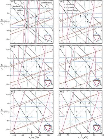
Perfectly plastic yield surfaces (Fig. 5) show that lattice strengths are limited to a few percent of the yield strength of the constituents over the range of admissible and practical skew angles. In most cases, failure by yielding initiates in the Type-1 members (blue and green) with the exception of the highest lowest skew angle, θ = 27°. Plotted in Fig. 5 are the failure surfaces for elastic buckling, initial yielding, and gross axial yielding (member tensile engineering strength). The stresses necessary to induce elastic buckling are much higher than the loads to cause plastic yielding and are an unlikely mode of failure. Three failure points are calculated with 3D FE: the onset of plasticity, the 0.2% yield strain, and the ultimate strength, plotted with ●, ▲, and ■, respectively.
Yield surfaces for the lattice geometries depicted in Fig. 1. Three-dimensional FE results for first yield (circles), 0.2% yield strain (triangles), and ultimate strength (squares) generally agree with results from simple beam FE models used to generate yield surfaces (dashed and solid lines). States of equi-biaxial stress are marked with a dashed-dotted line. Solid lines indicate the onset of yielding, while dashed lines indicate the member ultimate tensile and elastic buckling engineering stresses, and the colors correspond to the color-coding of members (inset legends). Each line forms a continuous surface that encompasses the state of zero stress at the origin (center). Loading cases that cause failure are the vectors in this stress space that originate at the origin and reach or traverse the most restrictive boundary in any direction. Initial yield is well predicted by simple FE models, as is the ultimate strength. Under states of equi-biaxial stress, simultaneous failure of all Type-1 members is predicted (confluence of green-blue lines). The failure surfaces for axial and initial yielding in Type-2 members also converge under states of equi-biaxial stress, due to the absence of bending under these conditions.

The failure surfaces of Type-1 and -2 members converge under states of equi-biaxial stress (dashed-dotted line). Under these conditions, initial and simultaneous yield of all Type-1 members occurs first, followed by axial yielding of these members at a higher load; this is all prior to the onset of yielding in the inner Type-2 members. The failure surfaces for initial yield and ultimate strength also converge for Type-2 members, as they are subject to no bending under these loading conditions. This occurs at loads well in excess of those that causes failure in the Type-1 members. Failure is, in almost all cases, caused by a combination of bending and axial stresses in the continuous Type-1 sublattice.
Beam models only predict failure by elastic buckling in the most slender design, θ = 27°; however, this phenomenon does not manifest in the associated FE model. This is due to the fact that the beam models for failure do not account for the overlap of members in the joint regions [Figs. 1(g) and 1(h)], which reduces their effective lengths and increases their resistance to elastic buckling. Additionally, eigenmode calculations performed on the unit cells in Fig. 1, 2 × 2, and 4 × 4 configurations of these cells exhibited negligible differences in critical load so that single cell calculations serve as useful predictive measures for the performance of larger structures.
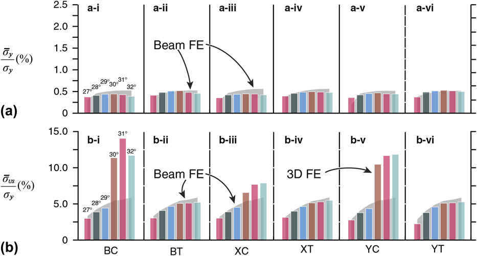
The yield surface results are summarized in Fig. 6, showing good agreement between the two models. Member widths increase monotonically with skew angle in this design scheme, which appears to be the main contributing factor to the ultimate strength. Beam and FE predictions for initial yield and ultimate strength are quantitatively and qualitatively similar (Fig. 6), indicating a peak in strength, around θ = 32°.
Macroscopic stress at initial yield (a) and at maximum load (b) in lattices under biaxial compression (BC), biaxial tension (BT), compression in the 1-direction (XC), tension in the 1-direction (XT), compression in the 2-direction (YC), and tension in the 2-direction (YT). 3D FE finite element and beam-element models show good agreement, with the exception of high relative density design subject to macroscopic compression, where lattices densify and the ultimate strength increases dramatically (b-i, -iii, and -v).

Under states of compressive stress arises the opportunity for neighboring unit cells to contact and the lattice to densify, as noted above. Under these conditions, the stiffness and strength of the lattice increases dramatically [Fig. 6(b-i, -iii, and -v)], as new load paths form and greater constraint is imposed. This effect is most dramatic under biaxial compression, where the ultimate strength is nearly double what it would otherwise be [Figs. 6(b-i)].
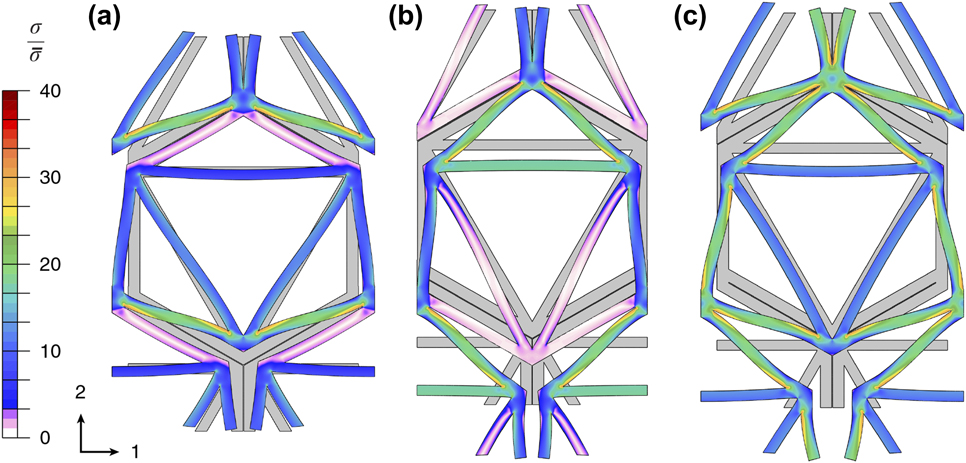
Failure initiates near the nodes where members intersect at sharp angles (Fig. 7). The magnitude of the peak stresses is inherently mesh-dependent, and while an effort was made to use similar-sized elements in the critical areas across the entire set of model geometries, there was some variation due to the wide span of geometries studied. Stiff networks of members transmit macroscopic loads so that subsets of members contribute little to the structural response under states of uniaxial loading [Figs. 7(a) and 7(b)]. Under biaxial loads, all members carry substantial stress, and the structural efficiency is near maximum (see Sec. III.B.2).
Tensile equivalent stress distributions at initial yield in the lattice from Fig. 1 having a skew angle of θ = 30° (i.e., the applied loads are given in Fig. 5 by circles). Shown are (a) tension applied to the lattice in the 1-direction, (b) tension applied in the 2-direction, and (c) equi-biaxial tension. Local stresses are normalized by the applied tensile equivalent stress. Displacements shown in the figures are scaled 50× to reveal the nature of the deformations involved, with the grey lattice depicting the undeformed configuration. Stress distributions at initial yield are similar under tension (shown) and compression (not shown). Under tension, the hexagonally arranged Type-1 members rotate toward the interior of the unit cell in an attempt to align with the triangular connectivity of the lattice, effectively decreasing the skew angle. Stress concentrations are associated with bending and shearing of Type-1 members, which is the continuous sublattice, where they meet at the nodes. Under equi-biaxial loading, all members carry significant load (c). In equi-biaxial tension, Type-1 members are primarily in tension and Type-2 members are subject to nearly pure axial compression, indicative of near optimal performance in this loading state.

2. Design efficiency
The GT theoretical bounds limit the biaxial modulus of multiphase composite systems. The bounds are a function of the intrinsic properties of the constituents, as well as the volume fraction of each of the three phases. As a result, for each design in Fig. 1—each with different volume fractions of the material—there are individual bounds (Fig. 8). The maximum stiffness is a function of the effective CTE,  $\bar{\alpha }$. The peak stiffness occurs in this system (where E 1 = E 2) when
 $\bar{\alpha } = {\alpha _{{\rm{RM}}}} = \left( {{\alpha _1}{V_{{\rm{f}},1}} + {\alpha _2}{V_{{\rm{f}},2}}} \right)/\left( {{V_{{\rm{f}},1}} + {V_{{\rm{f}},2}}} \right)$, is the rule of mixtures CTE. The stiffness decreases symmetrically for positive and negative deviations from this value of CTE. The absolutely stiffest systems are those with the highest relative densities, achieving 46% of the Voigt bound,
 ${\bar{K}_N} = 0.46$, at
 ${{\bar{\rho }} / {{\rho _{\rm{S}}}}} = 37\%$ when
 ${\bar{\alpha }_N} = 1.0$. The lowest density lattice, having
 ${{\bar{\rho }} / {{\rho _{\rm{S}}}}} = 17\%$, has
 ${\bar{K}_N} = 0.39$ when
 ${\bar{\alpha }_N} = 1.0$—a decrease of 28% for the same
 $\bar{\alpha }$. Conversely, for low (and high) CTE lattices, where
 ${\bar{\alpha }_N} \ll {\alpha _{{\rm{RM}}}}$ or
 ${\bar{\alpha }_N} \gg {\alpha _{{\rm{RM}}}}$, the most efficient systems are those with the lowest relative densities. In these cases, the system must experience large local deformations to accommodate the thermal loading and produce the desired response by mitigating, negating, or even reversing the intrinsic thermal response of the constituent materials. These deformations form stress concentrations associated with the bending of members. In low-density designs, where members are slender, these nonuniformities in the stress field are minimized, and the performance approaches that of the optimal pin-jointed parent structure in the low-density limit.
Thermal expansion plotted against stiffness for the lattices pictured in Fig. 1; the results of high-resolution FE simulations. For each design, the volume fraction of the two constituents is plotted with a pie graph, with the fraction of Type-1 material shown in blue, Type-2 in red, and the grey remainder is area not occupied by the material. Theoretical upper bounds on stiffness (solid lines) for all compositions have a maximum at the rule of mixtures CTE, where  ${\bar{\alpha }_N} = 1.0$, for this set of constituent materials. The designs with smaller skew angles and lower relative densities perform closer to theoretical stiffness bounds. The maximum stiffness performance for zero thermal expansion materials is largely independent of the volume fraction of constituents and is only a small fraction of the Voigt bound,
 $6.1\% \lt {\bar{K}_N} \lt 6.4\%$.

When  $\bar{\alpha } = 0$ as prescribed as the design goal in this study, the lowest density system becomes the highest performing, achieving over 93% of the theoretical limit, while the densest design only achieves 80%. Any deviation in performance from the theoretical limit at moderate to low relative densities is associated with the bending of members that only takes place when joints are bonded. In this design scheme, higher relative density is coupled with thicker members that lead to bulkier nodes with greater rotational stiffnesses. Thicker members have larger stress gradients that leads to degraded system efficiency. There is a point near
 ${\bar{\alpha }_N} \approx 0.5$ where the curves in Fig. 8 intersect, and a transition occurs between favoring high
 ${{\bar{\rho }} / {{\rho _{\rm{S}}}}}$ designs and low. There may be an opportunity to improve the design by adopting a design feature of pentamode materials,Reference Bückmann, Thiel, Kadic, Schittny and Wegener24 which have members with stiffness that taper to meet at low density, low rotational stiffness joints. Features of this design approach are exhibited by some shape optimized designs,Reference Sigmund and Torquato8,Reference Sigmund and Torquato25 where members meet at relatively slender joints at many locations.
IV. CONCLUDING DISCUSSION
A relatively low-cost design scheme is presented that allows for the design of tailorable CTE lattices with bonded joints that achieve a large fraction of the theoretical upper bounds for stiffness, offering low thermal expansion, low density, and high stiffness, in a completely defined and fabricable geometry. These lattices require slender members to perform most efficiently so that low-density designs are found to be the most efficient, and achieve a large fraction of the parent pin-jointed near optimal performance. However, slender designs suffer from large stress concentrations, associated with nodal regions where members intersect and overlap, as well as bending modes that create large stress gradients. The result is strengths and stiffnesses that are only a few percent of the constituent’s properties.
The bonded UCSB lattice design has some design features that are distinct from the parent pin-jointed structure, which open up areas of design space and new functionality. In addition to engineering the CTE of a unit cell, the effective Poisson’s ratio can be tailored independently over a range that encompasses  $\bar{\nu } = 0$. This creates the opportunity to design functionally graded structures whose properties vary locally in terms of CTE, stiffness, strength, and Poisson’s ratio. Low, zero, and negative Poisson’s ratio materials fill niche applications where dimensional stability under load is required so that the additional attribute of stability under thermal load may be advantageous in a subset of these cases. Many auxetic lattices designs, e.g., chiral lattices,Reference Spadoni and Ruzzene26 are bending dominated so that a stretching dominated auxetic lattice may possess some utility and novel combinations of properties.
The partial densification of designs with high skew angles can be used advantageously to increase stiffness, strength, and structural efficiency. At an upper operating temperature, lattices can be engineered to densify, increasing their stiffness and strength dramatically. The lattices in this study densified prematurely from thermal loading, the worst case being θ = 32°, where this occurs at a thermal excursion of ΔT ≈ 100°, achieving only 40% of the desired upper use temperature. Equation (5) serves only as an approximation, albeit a good one, of the required spacer dimension—having an error of ∼5% in this case—due to the complex thermomechanical response of the bimaterial joint regions that are not accurately captured by the simplified models. FE modeling and computer optimization are perhaps best suited for further design refinement, using the low cost design scheme in this work to generate seed designs that are already near the global optimum.
The bimaterial joints are likely sites of failure under both thermal and mechanical loading and clearly limit the performance of the lattices generated in this study. To mitigate the effect of these features, a third solid phase with an intermediate CTE can be introduced to form joint regions. This has two effects: (i) thermal stresses are reduced at the bimaterial interface and (ii) the location of the bonded joints can be moved away from the node regions where geometric stress concentrations are highest. This removes some of the design constraints and challenges which have proven problematic in previous efforts.Reference Steeves, Mercer, Antinucci, He and Evans15
Higher skew angles allow for larger deviations from the pin-jointed skew angle and the opportunity for increased absolute stiffness, but at the cost of lower structural efficiency. This decline, however, is only moderate in low thermal expansion lattices where the deviation from  ${\bar{\alpha }_{{\rm{RM}}}}$ is large and the set of theoretical bounds are tightly grouped so that no one regime of relative densities is favored. The highest relative density lattice is ∼2× denser, ∼3× stiffer, and still achieves 80% of the theoretical limit, compared to 93% for the lowest density, highest performing design. Therefore, there is a low penalty in terms of structural efficiency for designing functionally graded low CTE structures, whose unit cell geometry varies between neighboring cells.
Efficient designs are those with low  $\Delta {\bar{\alpha }_N} = \left| {{{\bar{\alpha }}_{{\rm{RM}}}} - {{\bar{\alpha }}_N}} \right|$. To achieve designs with low absolute CTE, it is then advantageous to select sets of constituents that have a low α1,Reference Berger, Mercer, McMeeking and Evans3 but with a large αRM to minimize the deviation,
 $\Delta \bar{\alpha }$. Another strategy to increase structural efficiency is to select a stiffer low CTE phase, E 1 > E 2. When the low CTE phase is stiffer, the peak in Fig. 8 drops below
 ${\bar{\alpha }_{{\rm{RM}}}}$, reducing
 $\Delta {\bar{\alpha }_N}$ independently of α1 and α2, increasing the potential structural efficiency. A parametric study, that varies E 1/E 2, σ1/σ2, and α1/α2 may help shed light on the opportunities for materials selection and the identification of material combinations that maximize structural efficiency and/or CTE.
Auxetic and zero Poisson ratio materials require similar local deformations through rotations as low CTE lattices to accommodate deformations along one axis while mitigating transverse strains. The UCSB lattice design already exhibits auxetic behavior at high skew angles for most material systems. This may present an opportunity to design materials that exhibit dimensional stability under a wide range of thermal and mechanical loading scenarios.
While the lattices in this study exhibit plasticity under a moderate thermal excursion, the titanium and aluminum lattices previously studied, on which these were based, did not fail under similar conditions. The yield strengths of these materials is considerably more (by ∼200–400%) than the notional material system in this work and would accommodate a much larger thermal excursion. In previous titanium–aluminum lattice designs where plasticity did occur,Reference Steeves, Mercer, Antinucci, He and Evans15 this was only a transient effect that persisted for less than 60 thermal cycles before abating. The situation of perfectly bonded joints in this study is the most rigorous case, where any sliding would reduce the stresses and the onset of plasticity.
While the lattice designs considered in this study can achieve a large fraction of theoretical upper bounds, over a substantial range of relative densities in the low density, lightweight regime, they fail due to large stress concentrations near the nodal regions. Structural optimization favors designs with smooth contours so that simple optimization, through the addition of fillets, may increase performance substantially. This can be done by moving the bimaterial joint away from the intersection of Type-1 and Type-2 members [Fig. 1(h)]. The cost would be a reduction in the effective length of either Type-1 or Type-2 members but can be done without modification of the basal triangulated geometry. This would complicate the thermal analysis provided in this work and would necessitate a larger CTE ratio to achieve a given effective CTE, but may be an opportunity for improved designs. The most promising application of this work may be to identify combinations of materials and geometries that nearly maximize ultimate performance, which can then be used as seed designs that are already near a global optimum in computer optimization routines, e.g., Ref. Reference Sigmund and Torquato25, for ultimate refinement. With this approach, it may be possible to design systems with unprecedented unique thermomechanical properties and maximal structural efficiency.