

In its biblical form, Leviathan is a sea monster. Herman Melville repeatedly makes reference to this archaic idea in his famous novel. On the one hand, Moby Dick describes the whale as a Leviathan to underscore the monstrous aspects of this “ignoble” organism and to compare it with similar sea monsters, e.g. sword-fishes and sharks (Melville [1851] Reference Melville2003, 457, 589). On the other hand, whales are also labeled Leviathans when Melville's narrator Ishmael, drawing on geological, palaeontological, and anatomical knowledge, speculates about the early evolution of these organisms. Referring back to a visit to a museum of natural history, Ishmael recounts: “When I stand among these mighty Leviathan skeletons, skulls, tusks, jaws, ribs, and vertebrae . . . I am, by a flood, borne back to that period ere time itself can be said to have begun; for time began with man” (ibid., 498).
With this observation, Ishmael implicitly raises two objections against the famous sentence from Thomas Hobbes's philosophical treatise, according to which the Leviathan was created “by art” and is “but an artificial man.” For Melville – who quotes Hobbes’ sentence on the first pages of his novel (ibid., xxvviii) – the Leviathan is obviously created by nature, i.e. non-artificially, and, at the same time, is a being that transcends mankind because it “comes floundering down upon us from the head-waters of the Eternities” (ibid., 501).
Hobbes conceived of the Leviathan in rather different terms. To the political philosopher the “great Leviathan” represented the “Commonwealth or State (in Latin, Civitas).” In Melville, this is apparently not the case. However, even Moby Dick ties the image of the whale to the notion of a community, i.e. the small group of hunters that, under the command of a dubious captain, work on a ship meant to track down and kill the white whale.
It has often been noted that Melville's novel refers to and relies on the scientific discourses of his time when describing the evolution, the various species, the behavior and the material properties of whales.Footnote 1 In fact, the entire novel can be read as a rather ambitious attempt at “not overlooking the minutest seminal germs of his blood, and spinning him out to the uttermost coil of his bowels” (ibid., 496). As a consequence, it does not come as a surprise when besides the anatomy and physiology of the whale even its superficial features are discussed. Chapter 68 of Moby Dick is devoted to the “skin of the whale” and the question of what it is and where it begins.
Initially, Ishmael's opinions on this matter seem to be straightforward, since he equates the skin with the blubber, which in turn he describes as “something of the consistence of firm, close-grained beef, but tougher, more elastic and compact.” Its thickness, he continues, ranges from “eight or ten to twelve and fifteen inches” (ibid., 332). But then Ishmael suggests that there is also something like the skin of the skin:
From the unmarred dead body of the whale, you may scrape off with your hands an infinitely thin, transparent substance, somewhat resembling the thinnest shreds of isinglass, only it is almost as flexible and soft as satin; that is, previous to being dried, when it not only contracts and thickens, but becomes rather hard and brittle. I have several such dried bits, which I use for marks in my whale-books. It is transparent, as I said before; and being laid upon the printed page, I have sometimes pleased myself with fancying it exerted a magnifying influence. (Ibid.)
Reading whale-books by means of whale skins seems like a rather fantastic or at least complicated assemblage. Ishmael has a similar impression and, in the next paragraph, brings us back to the body of the whale, more precisely: the Sperm whale and its “visible surface.” According to Ishmael, this surface sometimes resembles a piece of art:
Almost invariably it is all over obliquely crossed and re-crossed with numberless straight marks in thick array, something like those in the finest Italian line engravings. But these marks do not seem to be impressed upon the isinglass substance above mentioned, but seem to be seen through it, as if they were engraved upon the body itself. Nor is this all. In some instances, to the quick, observant eye, those linear marks, as in a veritable engraving, but afford the ground for far other delineations. These are hieroglyphical; that is, if you call those mysterious cyphers on the walls of pyramids hieroglyphics, then that is the proper word to use in the present connexion. (Ibid., 333)
To Ishmael, “the mystic-marked whale” eventually remains “undecipherable.” In contrast, recent historians of science are rather convinced that they are able to decipher the engravings and linear marks on their Leviathan – science itself –, or at least that this task is worth the effort. Inspired by Jacques Derrida's Grammatology (Reference Derrida and Spivak1976) Bruno Latour's (Reference Latour1987) “inscription devices” and – to a lesser degree – Friedrich Kittler's (Reference Kittler, Metteer, Cullens and Wellbery1990) “notation systems” (Aufschreibesysteme), historians have developed an emphatic interest in scientific hieroglyphs of all kinds over the past few years: from Marey's physiological curves to the trajectories of particles in bubble chambers and the coded sequences of genetic information (see, for example, Dagognet Reference Dagognet, Galeta and Herman1992; Galison Reference Galison1997; Rheinberger Reference Rheinberger1997).
It is beyond doubt that these studies, by focusing on the material culture of the lab, have largely contributed to expanding and deepening our knowledge of the technological prerequisites of dynamic research. In addition, they have enhanced our understanding of writing and translating practices as important, if not crucial components of the research process. However, up until today comparatively little attention has been paid to the concrete interfaces between “material technology” and “literary technology” (to quote from Shapin and Schaffer's by now classical Leviathan and the Air Pump) (Shapin and Schaffer Reference Shapin and Schaffer1985, 25; emphasis in the original).Footnote 2 In fact, the interstice between instruments and machines on the one side and traces, signs, and writing on the other has often been neglected.
For example, in almost all of the important studies that have been devoted to the role of notebooks in the laboratory, the paper that was used in the practice of note taking has remained a rather poorly historicized matter (see, for example, Holmes, Renn, and Rheinberger Reference Holmes, Renn and Rheinberger2003). Conversely, the history of computation has rarely contextualized the fact that the materiality of recording and storing surfaces have significantly changed over time. Before electromagnetic tape recordings became a standard in computer technology in the 1950s, cardboard punch cards and celluloid were used for storing data (see, for example, Lévi Reference Lévi and Serres1995). Even historical investigations concerning the role of photography in scientific practice have only dealt in passing with the different surfaces that allowed, to various degrees, for fixing “photogenic drawings” – from the pewter plate covered with bitumen in Nicéphore Niépce to the silver-coated copperplates in Daguerre and the paper negatives in Talbot (see, for example, Tucker Reference Tucker2006). In short, while the recent history of science has often stated (and proven) its interest in “inscription devices,” inscription surfaces have been largely overlooked as an important object of historical analysis.Footnote 3
This paper argues that inscription surfaces should receive more historical attention. The first and most obvious reason is because these surfaces have considerable consequences for the production and storage of scientific records. The specific properties of inscription surfaces have a crucial impact on whether or not it is possible to write down measurements at the laboratory bench, and they determine to what extent traces will remain from the experimental process, i.e. if records can be kept (and if so, how long) in the archive and the libraries. In this sense, inscription surfaces are an important, if not critical component of scientific research.
Secondly, in many cases inscription surfaces figure as an interesting object of scientific research. Together with chemists and physicists, archaeologists, paleographs, and archivists have investigated (and continue to study) the composition of paper and similar surfaces by means of laboratory techniques in order to determine the specific age of historical documents. In turn, science has contributed in numerous ways to developing innovative inscription surfaces. For example, it was the context of bacteriological research that, in the late nineteenth century, opened up the possibility to integrate light-sensitive silver bromide into layers of gelantin, thereby defining one of the basic material principles of analog photography that is still with us today (Baatz Reference Baatz2008).
Thirdly – and this is the focus of the present paper – inscription surfaces are often situated in interesting ways between culture and nature, or machine and organism. A case in point is paper. Through its materiality, it refers us back from the desk or the laboratory bench to the world of plants and trees (see, for example, Febvre and Martin Reference Febvre, Martin and Gerard1997, 29–44). Similarly, photography often relies on natural resources. When albumine was introduced as a means for coating copying paper, photography turned into a veritable industry of image production. Around 1870, paper factories used up to 50,000 chicken eggs per day in order to produce photographic surfaces. Accordingly, what Walter Benjamin ([1936] [1955] Reference Benjamin, Zohn and Arendt1969) famously termed the “mechanical reproduction” of images was based, to considerable degrees, on the property of organic reproduction.
Drawing on a well-known example, the present article aims at contributing to further investigations concerning the inscription surfaces used in scientific practice. While the general approach adopted here might be termed “semaphorological” (derived from Greek terms sema, “sign, signal,” and phoros, “someone or something that bears or carries”),Footnote 4 the concrete reference point for the following are the famous time-measuring experiments that German physiologist Hermann von Helmholtz conducted in Königsberg in the early 1850s, i.e. at about the same time Melville published his novel. Similar to Melville, Helmholtz was interested in the nature of time – and the time of nature. However, this Hermann's focus was not on the “period ere time itself can be said to have begun.” The target of Helmholtz's experiments was the here and now of living organisms, in particular frogs and humans. Relying on instruments such as the galvanometer and the myograph, Helmholtz carried out measurements of the propagation speed of stimulations in living nerves.
To historians of science, these measurements appear as one of the crucial experiments in the development of the modern life sciences. For example, Frederic Holmes and Kathryn Olesko have highlighted the ingenuity and elegance of these experiments and compared their historical importance to Lavoisier's chemical investigations into the composition of oxygen, Mendel's hybridization trials with peas, and the Meselson-Stahl experiment concerning semiconservative DNA replication (Holmes and Olesko Reference Holmes, Olesko and Wise1994, 198; see also Olesko and Holmes Reference Olesko, Holmes and Cahan1993).
It is hardly surprising, then, that the existing historical literature on Helmholtz's time experiments is extensive. Besides Holmes and Olesko (Reference Holmes, Olesko and Wise1994), authors such as Hebbel E. Hoff and Leslie A. Geddes (Reference Hoff and Geddes1959; Reference Hoff and Geddes1960a; Reference Hoff and Geddes1960b); Wilhelm Blasius (Reference Blasius and Rothschuh1964); Soraya de Chadarevian (Reference Chadarevian1993); Robert Brain and Norton Wise (Reference Brain, Wise and Krüger1994); Claude Debru (Reference Debru2001); as well as Stanley Finger and Nicholas Wade (Reference Finger and Wade2002) have investigated Helmholtz's time experiments from historical points of view. Many of these studies have devoted special attention to the material technologies that Helmholtz applied in his time measurements, in particular the so-called “graphic method.”Footnote 5 In addition, the iconography of the curve images that Helmholtz produced by means of his “myograph”Footnote 6 has been widely acknowledged and discussed in the historical literature (in particular, see Wise Reference Wise2007 and Wise Reference Wise2008). According to Holmes and Olesko, Helmholtz's curve images devised a general “image of precision” that had a huge impact on the scientific practice of the life sciences in the late nineteenth and early twentieth centuries.
However, comparatively little attention has been paid to the materials that Helmholtz used for recording and fixing his curve images. While the curve recordings were made on a glass cylinder, Helmholtz used isinglass, i.e. an adhesive organic substance derived from fish, to remove the curves from the cylinder and preserve them for further processing in drawings and publications. In contrast to Melville's Ishmael, Helmholtz was convinced that the “linear marks” on this skin-like surface could not only be deciphered, but, even more, were particularly clear representations of the physiological time he was investigating in his experiments.
Throughout the nineteenth century, isinglass – in Latin Colla piscium or Ichtycolla, in German Fischleim or Hausenblase – was used for many purposes, including the clarification of wine and beer, the repair of broken porcelain and glass, as well as the production of artificial pearls. However, in contrast to what Melville suggests in his novel, isinglass was not derived from the outer skin of a sea monster, but from its inner organs. According to the 1910 edition of the Encyclopaedia Britannica, isinglass is “a pure form of commercial gelatin obtained from the swimming bladder or sound of several species of fish,” in particular sturgeons. This explains where the German term “Hausenblase” comes from, namely “sturgeon's bladder.” The corresponding Dutch term is huisenblas. As the Encyclopaedia suggests, the latter served as a model for the English expression “isinglass” (Encyclopaedia Britannica 1910, 872).
Focusing on this surface substance, the present study reexamines Helmholtz's famous time experiments. The general argument is that the curves Helmholtz recorded were indeed “images of precision,” as Holmes and Olesko have suggested – but not precise images. The main purpose of the curves consisted not in measuring but in depicting time. More precisely, Helmholtz used his curves to illustrate the basic principle of his time experiments, which consisted of stimulating a nerve muscle-preparation in successive trials at two different points on the nerve and deducing from the differences in contraction time the corresponding time the nervous stimulations needed to travel between these two points. When recording these successive trials by means of the myograph, the interstice between two curves corresponded to the time interval required for the propagation of stimulations in the nerve.Footnote 7
The first part of the present article will reconsider the position of Helmholtz's curve images in the research process. It will show that Helmholtz, in his precise measurements of the propagation speed of nervous stimulations, initially did not use the graphic method but relied on electromagnetism. His basic procedure consisted of turning a galvanometer into a precision timer – a method initially suggested by the French physicist Claude Servais Mathias Pouillet in the mid-1840s. However, only after combining the galvanometer method with additional knowledge, both theoretical and practical, which Helmholtz derived from Carl Friedrich Gauss's and Wilhelm Weber's work on torsion balances, was he able to successfully conduct his physiological time measurements at Königsberg University in the winter of 1849–1850.
The second part presents and discusses the reactions that Helmholtz's first publication concerning his time experiments provoked in the academic public. Helmholtz's “Preliminary Report” (1850a) on the propagation speed of nervous stimulations was met with considerable reluctance and confusion at the Academies of Science in Berlin and Paris. The problem was not just to understand the details of a highly innovative method of meansurement but also to fully grasp the physiological nature of the object that had been investigated. Was the speed of nervous stimulations a constant or a highly variable factor? Could it really be the case that nervous stimulations traveled through the body at a much slower speed than electricity and/or sound?
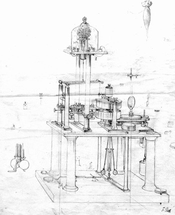
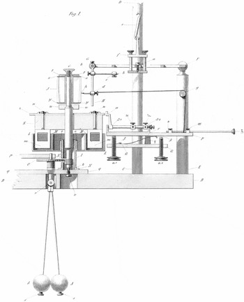
The third part shows that Helmholtz's disappointing experience with the public reception of his pioneering experiments led him to reconsider the use of the graphic method. Before his move to Königsberg, Helmholtz had used curve recordings in a series of explorative experiments concerning the physiology of muscle activity. However, once he had settled in Könisgberg, Helmholtz discarded this method because he was convinced that the Pouillet method would lead to much more precise results. Given the problems he had encountered in communicating the methods and results of his time experiments to the academic public, he decided, however, to return to the method of curve recordings several months later. In September 1850, he ordered a corresponding instrument that subsequently was termed the “Helmholtz myographion” (see fig. 1). The main purpose of this instrument was not to conduct further measurements in nervous stimulations but to present these experiments at other universities in order to directly convince the academic public that the object of his research was clearly defined and the experimental scheme he had applied to its study was indeed functioning.
Helmholtz myograph, ca. 1860. Under a glass cupola a muscle preparation is kept together with a wet sponge for preventing it from drying out. The muscle preparation is tied to a lever which moves up when the muscle contracts upon electric stimulation. Attached to a stick, the lever carries a steel needle that inscribes the corresponding movements onto a rotating glass cylinder driven by a clockwork. Massive flywheels and a centrifugal pendulum secure and control rotations as uniformly as possible. Drawing by Friedrich Veith, Heidelberg (see also fig. 4).

At the same time, Helmholtz used his new instrument to demonstrate the basic structure of his investigation to the Paris Academy of Science. Following up on the French translation of his “Preliminary Report” (Helmholtz Reference Helmholtz1850d), he submitted a “Second Note on the Propagation Speed of the Nervous Agent” (Helmholtz Reference Helmholtz1851a) to the Academy in the fall of 1851 (see below, Table I). It is in this connection that isinglass played a decisive role: Helmholtz used this organic substance in order to produce a kind of fingerprint of the curve images the myograph had recorded on its glass cylinder. Together with an addendum explaining the curve images (Helmholtz Reference Helmholtz1851b), he sent the manuscript of his “Second Note” to Paris. Part of his explanatory addendum were schematic drawings of the curves that were described and discussed in considerable detail. Taken together, the manuscript of the “Second Note” and the curve images were meant to present the object and method of Helmholtz's time experiments to the academic public in France.
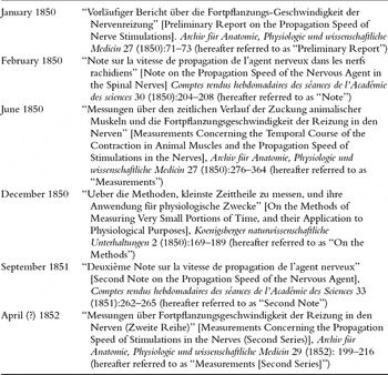
Chronological overview of the major publications by Helmholtz with respect to his psycho-physiological time experiments, 1850–1852.

Despite the fact that historians of science have devoted numerous studies to Helmholtz's pioneering time measurements it seems appropriate, before entering the historical account, to rehearse the succession of articles that Helmholtz published between 1850 and 1852 about his experiments concerning the propagation speed of stimulations in the nerve. Table I offers a chronological overview of these six articles and indicates the corresponding terms that will be used in the following when referring to them.
Equally important is to recall the rather international context of Helmholtz's time experiments. As Hoff and Geddes (Reference Hoff and Geddes1959, 14–17) have shown, it was the Italian electrophysiologist Carlo Matteucci who had used electromagnetic and graphic procedures in order to measure the speed of movements in muscle preparations from frogs as early as 1847. As a consequence, the rush in which Helmholtz published his “Preliminary Report” in January 1850 should not only be seen as an expression of the “newness” of his results. In addition, it should be related to Matteuccis ongoing publication of papers on related issues in the Philosophical Transactions of the Royal Society of London (on Matteucci, see Clarke and Jacyna Reference Clarke and Jacyna1987, 196–211).
Moreover, it is worth recalling that Helmholtz conducted his experiments in Königsberg, not Berlin. This is why the rather intense correspondence between him and his Berlin-based friend and colleague, Emil du Bois-Reymond, becomes especially important when Helmholtz set out to publicize his initial findings in Berlin and Paris. Given his Hugenot background, du Bois-Reymond was fluent in French and acted as a translator for Helmholtz's texts before they were sent to the Parisian Academy. In additon, du Bois-Reymond travelled to Paris to present his own work in the spring of 1850. In this connection, he also tried to further explain the methods and results of the time experiments conducted by Helmholtz. Du Bois-Reymond's failure in transmitting the importance of these experiments to the French audience was an important motivation for Helmholtz to turn to curve images as a means to convince the same audience of the significance of his experiments.Footnote 8
1. The Galvanometer as Precision Timer
The winter of 1849–1850 was Helmholtz's first winter in Königsberg. At the end of August 1849, he had moved with his wife Olga from Potsdam to the former city of Kant, in order to succeed Ernst Brücke as professor of physiology and anatomy. After Helmholtz had finished his medical studies with Johannes Müller in Berlin and his part-time employment as an assistant at Müller's anatomical museum (which also implied some teaching in drawing at the Berlin Kunstakademie), his first important position at a German university was the professorship at Königsberg.Footnote 9
Helmholtz's doctoral thesis, published in 1842, had been mainly anatomical and visibly inspired by the new theory of cells put forth by Theodor Schwann and Matthias Schleiden. In his first research paper after the dissertation, Helmholtz investigated phenomena of fermentation and putrefication which, against the reigning vitalism of his time, he referred back to purely chemical processes. In 1845, he turned to the problem of muscular action, first conducting experiments on their “metabolism [Stoffverbrauch],” then, in 1848, investigating their “production of heat [Wärmeentwicklung].” During this period, Helmholtz's work shifted more and more in the direction of “Organic Physics” as it was programmatically advocated by du Bois-Reymond and other students of Müller (Lenoir Reference Lenoir1989, 197–245; Kremer Reference Kremer1990a, 237–255; 292–307; see also the earlier accounts, Fulton Reference Fulton1926, 42–47; and Mendelsohn Reference Mendelsohn1964).
On January 15, 1850, Helmholtz finished the first research paper elaborated in the Königsberg context. Its title was “Preliminary Report on the Propagation Speed of Nerve Stimulations.” The main topic of this report was the time measurements that he had conducted in the motor nerves of frogs. In the first lines Helmholtz summarizes the result of these measurements:
I have found that a measurable time passes while the stimulus, exercised by a momentary electric current on a frog's sciatic plexus, propagates to the point where the thigh nerves enter the calf muscle. In larger frogs, whose nerves were 50–60 mm long and which I had kept at a temperature of 2–6°C, while the temperature of the observation room lay between 11 and 15°, this time was between 0.0014 and 0.0020 of a second. (Helmholtz Reference Helmholtz1850a, 71)
The research machine behind these sentences consisted of a quasi-telegraphic coupling between a frog leg, a galvanometer, and a telescope in the laboratory that Helmholtz used in the Königsberg university building. In other words, the measurements first reported to the public used an essentially electromagnetic procedure rather than the “graphic method.” It is true that before his move to Königsberg Helmholtz had devised a “frog drawing machine” that was meant to automatically register muscle movements in a curve-like manner. However, several months later, in October 1849, Helmholtz informed du Bois-Reymond that he had conducted his experiments on muscle activity “according to an entirely new method” (Kirsten et al. Reference Kirsten1986, 87). This method made time visible on a scale – similar to a clock – so that it could be noted numerically.
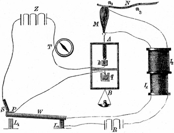
Inspired by the Italian pioneer of electrophysiology, Carlo Matteucci, and building upon previous work by German muscle physiologists such as Theodor Schwann and Gustav Valentin, Helmholtz adopted the electromagnetic time measuring method initially suggested by the French physicist Claude Pouillet (Reference Pouillet1844). Following Pouillet's suggestion to use the amount of deflection of a galvanometer needle as a means for determining the duration of extremely short electric impulses, Helmholtz had put together a rather complex physiological timing device (see fig. 2). Its most significant parts were a half wooden, half metal frame that allowed for hanging and stimulating the nerve-muscle preparation, a galvanometer (the needle of which was provided with a small mirror), and a telescope for reading off the deflection of the galvanometer needle on a remote scale with great accuracy. The tedious management of this set-up produced laboratory ciphers that Helmholtz, together his wife Olga, wrote down in a notebook (Helmholtz Reference Helmholtz1850g).
Schematic reconstruction of the set-up used by Helmholtz for determining the propagation speed of stimulations in the motor nerves of the frog. The set-up combined two electric circuits: one in which the battery R, by passing through the induction coils I1 and I2, could momentarily stimulate the nerve muscle preparation N/M; and another, which connected the galvanometer T to the battery Z. The switch S/P allowed both electric circuits to close at exactly the same time. The devices within the metallic frame A guaranteed that after the contraction of the frog muscle the time-measuring circuit was permanently interrupted. By placing the electrode at different points of the nerve (n1, n2) Helmholtz could deduce the time the motor nerve needed for conducting the stimulation. Note that the scheme does not include the glass cupola for moistening the muscle, the mirror on the galvanometer, the scale and the telescope for reading off the deflections of the galvanometer needle (reproduced from Kuhn Reference Kuhn1866, 1193).

In order to transform the deflections of the galvanometer needle into precise measurements of time, Helmholtz drew from his knowledge of torsion balances developed in the work that Carl Friedrich Gauss and Wilhelm Weber had done on terrestrial magnetism and telegraphy in Göttingen in the late 1830s. Unlike Pouillet, who had suggested using empirical tables for translating needle deflections into time measurements, Helmholtz aimed at mathematical precision. He stimulated the frog nerve at two different points, first rather close to the muscle, then in a more remote place. In both cases, it was determined how much time was needed for the muscle contraction to begin. From the differences between the results he obtained and taking into account the corresponding distance between the stimulated points on the nerve, he then deduced the propagation speed of the stimulation in the nerve.
This was the first manifestation of an experimental scheme or diagram that Helmholtz later used in his experiments with the myograph. Under the name “method of variation and subtraction” it paved the way for uncounted investigations concerning the problem of psychophysiological time in animals and humans.
For calculating his results, Helmholtz adopted the procedure suggested by Gauss and Weber. The starting point was provided by the general properties of his galvanometer. The decisive factor in this instrument was the spring constant of the magnetic needle suspended by means of fine thread of silk (Cocon). In the yearbook of the Magnetische Verein in Göttingen, Weber (Reference Weber, Gauss and Weber1837) had described the means and methods for determining this factor with great accuracy in 1836. In the same yearbook, Gauss (Reference Gauss, Gauss and Weber1838) had published an additional “Instruction for determining the spring constant of a magnetic needle.” As Helmholtz's extended article from the summer of 1850, the “Measurements” (see above, Table I), makes clear, Weber's text was his main reference (Helmholtz Reference Helmholtz1850e, 300).
First, Helmholtz determined the spring constant of his galvanometer needle. The second important factor was the deflection of the needle caused by a permanent electric current. Given the variations in voltage in the galvanic elements that were used as batteries, this factor had to be determined by means of the telescope every time a new series of trials was undertaken. As Helmholtz later explained, he was also aware of the fact “that the magnet could never be put in a state of absolute rest” (ibid., 298). As a consequence Helmholtz aimed at establishing a kind of average or “meridian” for the position of the needle in every trial. The required observations were entered as the third and fourth factor into the mathematical translation of needle deflections into time measurements. The fifth and last factor was the amount of deflection that could be observed when, following the stimulation of the nerve, the contraction had occurred. Thus, there was a total of five factors that Helmholtz had to take into account when transforming the needle deflections he observed into precise indications of time.
As sophisticated as this procedure was, there was a continual struggle with serious restrictions. The main problem was that, besides contraction time, the distance between the two points at which the nerve was stimulated entered into the result. As Helmholtz explained, due to the “great stretchability” of the nerves, determining this distance was “a very uncertain” business (ibid., 339). This uncertainty contributed to the fact that the results he presented in the “Preliminary Report” of January 1850 were distributed over a significant range: The numbers that were given corresponded to a propagation speed between 25 and 43 meters per second.
Despite this fact, Helmholtz was convinced he had accomplished a pioneering experiment in measurement. In 1838, Johannes Müller, the professor of Helmholtz and du Bois-Reymond, had published his opinion concerning these kinds of measurements in his seminal textbook on physiology. In rather sober terms, Müller had opened up the section “Of the mode of propagation of nervous action in the different nerves” by stating that physiologists “shall probably never attain the power of measuring the velocity of nervous action” (Müller Reference Müller1837, 686, quoted in Müller Reference Müller and Baly1843, 532). Some ten year later, Helmholtz had managed to carry out these measurements by making use of electromagnetic procedures that were connected to the technological system of telegraphy.Footnote 10
2. The Preliminary Effects of the “Preliminary Report”
In early 1850 Helmholtz rushed to publish the “Preliminary Report” about his experiments. In January, he sent the corresponding manuscript to du Bois-Reymond in Berlin. In the accompanying letter, he made clear his ambition. Helmholtz kindly asked his friend “to officially present it [the “Preliminary Report”] to the Physical Society and to deposit it in its files to preserve priority” (Kirsten et al. Reference Kirsten1986, 90).Footnote 11
The priority that Helmholtz was eager to document did not refer to Johannes Müller who, in his textbook, had presented the wrong idea about the development of precision time measurements in physiology: Helmholtz had too much respect for his academic teacher, and Müller's recent research interests were far removed from Helmholtz's work, methodologically as well as thematically. Also, Helmholtz's claim of priority did not concern du Bois-Reymond who, in 1845 had suggested in general terms how to apply Pouillet's timing technology to the emerging field of muscle and nerve physiology.Footnote 12 The relation between the two was much too open, friendly, and cooperative, and du Bois-Reymond certainly would have been the wrong person to help Helmholtz to secure priority over himself.
By using the expression “preserve priority,” Helmholtz aimed at positioning (and temporalizing) his innovative work with respect to research activities on the international scale. In particular, Matteucci had started to study muscle actions by means of innovative timing devices as early as 1847. In this context, Matteucci used electromagnetic precision timers provided by Louis Bregeut, a French physicist and telegraph pioneer (Matteucci Reference Matteucci1847).
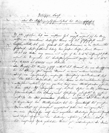
Facing the international competition in experimental physiology, Helmholtz did not restrict himself to sending his “Preliminary Report” to du Bois-Reymond. In addition, he sent similar letters, each accompanied by Olga's careful transcriptions of the manuscript (see fig. 3), to Johannes Müller and Alexander von Humboldt with the aim to have transmitted his report to the Academies of Science in Berlin and Paris. These letters produced a cascade of public presentations in German. Müller's was first. On January 21, 1850, he presented Helmholtz's “Preliminary Report” to the audience of the Royal Prussian Academy of Science in Berlin. Shortly thereafter, du Bois-Reymond took over. On February 1, he read Helmholtz's paper in front of a gathering of the Berlin Physical Society. Then followed the documentation in print. No less than three German journals printed Helmholtz's report in 1850: first the Bericht über die zur Bekanntmachung geeigneten Verhandlungen der Königlich Preussischen Akademie der Wissenschaften zu Berlin; later the Monatsberichte der Berliner Akademie (Helmholtz Reference Helmholtz1850b); then Müller's Archiv für Anatomie, Physiologie und wissenschaftliche Medicin (Helmholtz Reference Helmholtz1850a); and eventually Poggendorff's Annalen der Physik und Chemie (Helmholtz Reference Helmholtz1850c).
First page of the manuscript of Helmholtz's “Preliminary Report” (1850), written by his wife Olga. In this text, Helmholtz reports the initial results of his measurements concerning the propagation speed of stimulations in the nerve. The basis for these measurements had been provided by Pouillet's suggestion to use the deflections of a galvanometer needle as an indicator for measuring short intervals of electrical activity. The beginning of the text reads: “I have found that a measurable time passes. . .” (Ich habe gefunden, daß eine meßbare Zeit vergeht. . .).

These publications quickly contributed to disseminating Helmholtz's findings. However, the effects of this communication strategy were rather devastating. In March 1850, an obviously frustrated du Bois-Reymond remarked “with pride and sorrow” that in Berlin Helmholtz's time experiments had been “understood and appreciated” exclusively by himself. According to du Bois-Reymond, the reason for this failure was not – or not exclusively – due to the radical novelty of Helmholtz's research, but to the language of the “Preliminary Report” itself. In a critical mood, he wrote to his friend in Königsberg:
It's because – don't take this the wrong way – you presented the matter in so exceedingly obscure a manner that your report could at most count for a short instruction for reinventing the method. The result was that Müller did not reinvent it and that after his presentation, the Academy members imagined you failed to eliminate the time passing in the process that takes place in the muscle. I had to enlighten them one after the other, Riess, Dove, Magnus, Poggendorff, Mitscherlich, finally Müller himself who really didn't want to take it on at all. (Kirsten et al. Reference Kirsten1986, 92)
Alexander von Humboldt was equally puzzled. From Helmholtz's perspective, this must have been particularly unfortunate since von Humboldt was meant to send the “Preliminary Report” to the Parisian Academy of Science. At this time, the Parisian Academy considered it one of its central tasks to “determine the exact date of discoveries” (Crosland Reference Crosland1992, 248), and without any doubt Helmholtz had been particularly eager to “preserve priority” with the help of this internationally renowned institution. The problem remained. Von Humboldt did not understand Helmholtz's report. Almost in despair he wrote to du Bois-Reymond on January 18 that nowhere in the “Preliminary Report” had the measuring procedure been properly explained: “I’ll gladly send the excellent Helmholtz's attachment [the “Preliminary Report”] to Paris, but I find myself confronted with this form completely incomprehensible to me: one speaks of 14/10,000 of a second without indicating how such a portion of time is being measured” (Schwarz and Wenig Reference Schwarz and Wenig1997, 101).
Du Bois-Reymond did what he could. First he offered to translate the German text into a French version that could be published in the Comptes rendus. Then he proposed “reworking” Helmholtz's report during the translation in order to improve its “comprehensibility” (Kristen et al. Reference Kirsten1986, 92). As a result, the German and the French versions of Helmholtz's “Preliminary Report” display significant differences. The first difference concerns its clarity: Helmholtz had separated his report into six paragraphs; du Bois-Reymond arranged it into ten and numbered two of them. Helmholtz condensed his message into 19 sentences; du Bois-Reymond distributed it over 35. Finally, Helmholtz had placed the summary of his numerical results at the beginning of his report; du Bois-Reymond shifted the corresponding paragraph to the end of the text.
In addition, du Bois-Reymond added some explanatory remarks concerning the experimental set-up. In the German version, Helmholtz had only noted: “I measured the deflections [of the galvanometer needle] with mirror and telescope” (Helmholtz Reference Helmholtz1850a, 72), whereas in its French translation du Bois-Reymond wrote: “The measurements were taken, as in the apparatuses of Gauss and Weber, with the help of a mirror and a telescope” (Helmholtz Reference Helmholtz1850d, 204). Moreover, du Bois-Reymond's version of Helmholtz's text contains a footnote that translated Helmholtz's hundreds and thousands of a second into meters per second. In the French version, Helmholtz's central finding is rendered by the statement that stimulations travel through nerves at a speed of “25 to 43 meters per second” (Helmholtz Reference Helmholtz1850d, 206).
Von Humboldt was satisfied. In his eyes, the French version of Helmholtz's report had the status of “a new copy [neue Abschrift]” (Schwarz and Wenig Reference Schwarz and Wenig1997, 92) – a remarkable judgment that tends to turn the translation into an original text. In a letter to Helmholtz, von Humboldt then explained that du Bois-Reymond's translation of the “Preliminary Report” “rectified some expressions and clarified them” (Königsberger Reference Königsberger1902, 118). In a similar vein, du Bois-Reymond told his friend in Königsberg that, while translating and editing the text, he had “not added a single detail,” but “strictly” obeyed “the given.” However, he had taken the freedom to “inductively develop” it (Kirsten et al. Reference Kirsten1986, 92). This was to mean that the experimental process had been depicted according to the successive order that it probably followed in reality.Footnote 13 Then he left it up to Helmholtz's attention to verify this point and judge all the other details of the new text, with one exception: “The remark on the velocity per second is not mine but Humboldt’s” (ibid.).
In this form – rewritten in logical and historical order and supplemented by von Humboldt's footnote – the “Preliminary Report” was presented to the Parisian Academy of Science on February 25, 1850. The title of the report was “Note on the Propagation Speed of the Nervous Agent in the Spinal Nerves” (Helmholtz Reference Helmholtz1850d).
However, all the changes in and additions to Helmholtz's “Preliminary Report” could not change the fact that this publication was also met in the French context with considerable doubt. In fact, the “Note” seems to have been so peculiar that even the press commented upon Helmholtz's time experiments. Only two days after the presentation of the “Note” in the Academy of Science, the liberal newspaper Le National published a short report about Helmholtz's experiments in its monthly coverage of scientific news. After a rather sober summary of the results presented in Helmholtz's “Note,” the two anonymous authors of the article, signing “D. and T.,” remarked: “No need to add that it was the frogs who had to pay the price of this work. Frog aside, Monsieur Helmottz's [sic] work leaves something to be desired” (D. and T. 1850, 1).
What precisely “D. and T.” meant with quelque chose à désirer remains unclear to today's readers. However, their comment was part of a critical reflection about science. The “something” that was missing in Helmholtz's “Note” was apparently any effort to go beyond what “D. and T.” saw as the rather boring and irrelevant routine of scientific work. From this perspective, Helmholtz failed to contribute to rescuing what the authors saw as the “helpless Academy” (ibid.).
Helmholtz's first reaction to this criticism was to be unimpressed. The National was not available for him in Königsberg,Footnote 14 and he only learned about the article from du Bois-Reymond, who added that this newspaper was obviously “ridiculing” him (Kirsten et al. Reference Kirsten1986, 93). Helmholtz attributed the entire affair to national and cultural differences. A short time later, he wrote to his father: “A benevolent reception by the French of such things from Germans just isn't possible, and the preliminary purpose [vorläufige Zweck] of drawing their attention has been fulfilled” (Königsberger Reference Königsberger1902, 121). The “preliminary purpose” of the “Prelimary Report” . . . at this point the problem of dating a discovery, of securing priority, which was so crucial in Helmholtz's first article about his time measurements, transforms itself into a doubling of provisional aspects.
Du Bois-Reymond was less sanguine. Against the background of his own experiences with the reception of his contributions to electrophysiology in France – since the summer of 1849, Léon Foucault and other French Académiciens had publicly polemicized against his galvanometer experiments with human test subjects, claiming that they were “misleading” and utterly “romantic” –du Bois-Reymond seemed to fear that the Parisian public was about to attack another physiologist from Müller's research school on the basis of unjustified and unfair arguments (see Finkelstein Reference Finkelstein2003). In any case, this was du Bois-Reymond's perception of the situation in Paris and what he transmitted from Berlin to Königsberg. In the eyes of the Berlin physiologist, the press was attacking his friend Helmholtz, “just as they did against me, back then” (Kirsten et al. Reference Kirsten1986, 93).
However, concrete evidence for this judgment could only be provided by the fact that the National had changed Helmholtz's name to “Helmottz” [sic] and presented him as “Professeur de pathologie,” not as a physiologist. Without being asked to, du Bois-Reymond promised “J’y mettrai ordre,” I’ll settle this (Kirsten et al. Reference Kirsten1986, 93). On March 15, 1850, he was on his way from Berlin to the “capital of the nineteenth century” where he wanted to demonstrate his galvanometer experiments with human test subjects and put an end to his own priority disputes with Matteucci (see Finkelstein Reference Finkelstein2003).
Du Bois-Reymond did not lose any time. From the start he used his public interventions to promote Helmholtz's physiological time experiments. On March 25, in his first talk at the Academy of Science, he first focused on presenting the historical and methodological prerequisites of his own work in electrophysiology. After some explanations concerning eighteenth-century theories of irritation and the objections that had been raised against the presumed identity of esprit animaux and electrical currents by von Haller and Lecat, du Bois-Reymond jumped into the present and talked about the work of his Königsberg friend and colleague: “Mr. Helmholtz's experiments have shown that the propagation speed of the nervous agent is more than ten times less than that of sound in the air and thus more than one hundred times less than that of electricity in copper! . . . Accordingly, it is impossible to identify the nervous agent with electricity” (du Bois-Reymond n.d., 4).
Du Bois-Reymond did his best to convince his audience. However, his talk had little to no effect on the Académiciens. In fact, most of the present members of this learned society were not amused by the rather extended historical explanations du Bois-Reymond had offered at the beginning of his talk. At least this can be concluded by the fact that the Berlin physiologist, when preparing his talk to be published in the Comptes rendus, cut down the historical introduction to a minimum and highlighted instead the effect of contraction on the electric currents emitted by the muscle – a key topic of the first volume of his book Untersuchungen über thierische Elektricität published in 1849 (Finkelstein Reference Finkelstein2003, 289).
The reactions of the audience to Helmholtz's time experiments were devastating. “Your measuring of the velocity of the nervous agent was ridiculed in the Academy,” du Bois-Reymond reported in August 1850 to Helmholtz (Kirsten et al. Reference Kirsten1986, 100). Completely bewildered, he wrote from Paris to his colleague Carl Ludwig in Leipzig that the physiologists in France think “Helmholtz is a madman” (du Bois-Reymond Reference Du Bois-Reymond1927, 88–89).
All the same, du Bois-Reymond made a second attempt to present and defend Helmholtz's work, this time in a talk delivered to the Société Philomatique on March 30. But here again, the response to the time experiments performed by Helmholtz was rather disappointing: “Although nobody dared to object publicly, I was plagued silently by the most stupid of doubts and objections” (Kirsten et al. Reference Kirsten1986, 100). It was against these doubts and objections that Helmholtz started to work with myograph and isinglass.
3. Placing Curves “before the eyes of the Academy”
During the summer of 1850 Helmholtz began to understand that something had gone wrong. In a letter to du Bois-Reymond from April 22, he had admitted that writing a short report about an important experiment might cause problems: “The redaction of such a note is so difficult because its main purpose is to serve as a short hint for the expert who has to add details to it by invention” (ibid., 96–97). Several weeks later, and apparently alarmed by what du Bois-Reymond had told him about the reception of his time experiments in Paris, Helmholtz was no longer willing to rely on “experts” and their presumed ability to spell out the prerequisites and implications of an experiment. He started writing an extended article in German about his electromagnetic time measurements.Footnote 15
As a sequel to his “Preliminary Report,” this article, titled “Measurements Concerning the Temporal Course of the Contraction in Animal Muscles and the Propagation Speed of Stimulations in the Nerves,” was published in Müller's Archiv für Anatomie, Physiologie und wissenschaftliche Medicin in the summer of 1850 (Helmholtz Reference Helmholtz1850e). In no less than 90 pages Helmholtz explained his use of the electromagnetic Pouillet method and spelled out his findings in detail. In fact, his report was so extensive that it was never translated in its entirety into any other language.Footnote 16
In a second step, Hemholtz extended his time experiments from frogs to human beings. In a similar vein, du Bois-Reymond had moved from animal to human physiology in order to convincingly demonstrate one of his crucial findings in the realm of electrophysiology, i.e. the so-called negative variation of muscular currents in frogs. By means of a quasi-athletic experiment, du Bois-Reymond provided evidence for the fact that the contraction of muscles in human arms produced deflections of a galvanometer needle. During his time in Berlin, Helmholtz had witnessed corresponding demonstrations by du Bois-Reymond (Finkelstein Reference Finkelstein2003, 281–283). Starting in April 1850 he conducted his time experiments not just in frogs, but also in human test subjects, with Olga acting as his assistant (Kirsten et al. Reference Kirsten1986, 94–95).
The first results of these experiments were presented by Helmholtz during a popular talk in Königsberg in December 1850 (Helmholtz Reference Helmholtz1850f).Footnote 17 Before a general audience of the Physical-Agricultural Society he explained how he had conducted physiological time measurements in an “assistant,” i.e. Olga, and himself. By means of comparative measurements of electric stimulations in the toe, the hand, and other parts of the body Helmholtz arrived at the conclusion that “the message [Nachricht] of an impression made upon the ends of the nerves in communication with the skin is transmitted to the brain with a velocity which does not vary in different individuals, nor at different times, of about 60 metres [195 feet] per second” (here quoted from Helmholtz Reference Helmholtz1853, 324; translation modified).
Trying to illustrate these time relations given in the human body, Helmholtz made reference to comparative anatomy at the end of his lecture. In order to explain what he called the “inaccuracy of our impressions of time,” in other words, the fact “that fine differences [of time] cannot be appreciated simply because the nerves cannot operate more quickly,” Helmholtz compared the human body to that of a whale:
Happily the distances are short which have to be traversed before they [the nervous stimulations] reach the [human] brain, otherwise our self-consciousness would lag far behind the present. . . . With an ordinary whale the case is perhaps more dubious; for in all probability the animal does not feel a wound near its tail until a second after it has been inflicted, and requires another second to send the command to the tail to defend itself. (Ibid., 325)
The next step was the skin of the whale, or rather the skin of the skin, a transparent substance making visible the “finest line engravings” as Melville had described them. The next step was isinglass.
In September 1850, Helmholtz turned to the Königsberg instrument maker Egbert Rekoss, with whom he had already collaborated in the construction of the ophthalmoscope (the other major achievement of his work in Königsberg), and ordered new equipment for his time experiments, in particular a glass cylinder derived from a “thick, near-cylindrical champagne glass” (Helmholtz Reference Helmholtz1852, 206), a mobile lever, a stylus made of steel, and a new wooden frame for mounting the entire set-up. Once these pieces were at hand, Helmholtz retooled his initial experiment and repeated his study of frog nerves. This time, the semiotic output of his research machine did not consist of numbers, but of curves.
Helmholtz's turn to the graphic method seems surprising. Only a few weeks earlier, he had explicitly argued against the use of the graphic method for the purpose of precisely determining time. According to his 90 page-article on the “Measurements,” the “unavoidable fricton of the apparatus's individual parts” resulted in slowing down the organic movement under investigation, in this case the contraction of the frog muscle (Helmholtz Reference Helmholtz1850e, 283–284). However, faced with rather unexpected problems in communicating his methods and findings, Helmholtz pushed these critical observations to the side. As he explained in a letter to du Bois-Reymond in September 1850, the main argument in favor of the graphic method was not precision, but demonstrability: “I am having an apparatus with a rotating cylinder built for drawing lines with which I hope, among a number of other things, to place before everyone's eyes, in 5 minutes, the fact of the duration of propagation in nerves in an experiment.” Helmholtz explained this motivation for the turn to graphic recordings by continuing: “I plan on traveling with this [apparatus] to German [German-speaking] universities next summer and to give performances” (Kirsten et al. Reference Kirsten1986, 106).
This was precisely what Helmholtz did one year later, in August and September 1851. He visited physiological research and teaching facilities in Heidelberg, Zurich, Vienna, und other cities, in order to demonstrate, by means of his new apparatus, the fact of propagation time in the living nerve. He wrote to Olga: “The frog curves, I demonstrate them . . . everywhere” (Kremer Reference Kremer1990b, 52). He also sent tracings to Alexander von Humboldt – for no other reason but to “impress” the learned naturalist “with something to look at” (Kirsten et al. Reference Kirsten1986, 111).
The preparation of the “Second Note” falls into the same period (Helmholtz Reference Helmholtz1851a). During the autumn of 1851 Helmholtz prepared the article in which he presented his new method to the Parisian Academy of Science. His “Second Note” was read to the Académie on September 1, 1851. Through its title, it makes explicit reference to the “Note” that Helmholtz had published in Comptes rendus the year before. However, in contrast to what the title suggests, this article did not report any new findings concerning the propagation speed of stimulations in the nerve. Instead, the presentation of the new graphic method dominated Helmholtz's account. In fact, the first part of the “Second Note” only summarizes known results that had been obtained by means of the electromagnetic Pouillet method, whereas the second part is entirely devoted to presenting the new apparatus, the “myographion” or “myograph” as it would be called some years later (see fig. 4, and note 6).
Helmholtz's drawing of the central components of his myograph (1852). The drawing focuses on the glass cylinder, the steel stylus, the metal frame carrying it, and the rather extended apparatus for securing and controlling even rotations. Helmholtz omitted the muscle preparation and its hanging arrangement (see, however, fig. 1 for a view of the entire set-up).

Helmholtz opens his presentation of the myograph by way of some critical remarks concerning the use of the Pouillet method for the purpose of time measurements. This method, he explained, certainly was “ingenious,” but its application in physiological contexts entailed “great difficulties.” Above all, it required a “long and tiresome series of observations” to secure the results obtained against all possible doubt. With this statement, Helmholtz implicitly made reference to the large amount of factors that had to be taken into account in order to transform the deflections of the galvanometer needle into values of time. He then went on: “I therefore looked for a more expedient method, and I have the good fortune to have found one whose principle is very simple and that is much more easily put into practice. It allows us to show the same facts in the space of a few minutes, and with only a small number of experiments” (Helmholtz Reference Helmholtz1851a, 263).
For this “new method” Helmholtz also quotes a concrete model. However, it is not Carl Ludwig who was referenced here as the pioneering figure who had introduced, in 1847, the kymograph into the practice of experimental physiology. Nor is it James Watt, whose indicator diagrams figured, since Matteucci, as an oft-cited model for Ludwig's kymograph (Matteucci Reference Matteucci1847, 246).Footnote 18 Instead, Helmholtz refers to the British physician and physicist Thomas Young. In his Lectures on Natural Philosophy, Young had described an inscription device in which a fixed “pin” would leave line-form traces on a drum rotating at high speed. This reference seems all the more appropriate insofar as Young, in contrast to both Ludwig and Watt, had explicitly presented his device as a means for conducting measurements of time, i.e. as a “chronometer for measuring minute portions of time” (Young Reference Young1807, plate xv, fig. 198). However, Young had not ventured into applying this chronometer to medical or biological investigations (Reiser Reference Reiser1979, 100).
As we have seen, Helmholtz's turn to the graphic method was also due to a specific economy of scientific time. As the “Second Note” makes clear, this economy does not directly refer to chronometry, i.e. the precise measurement of time. With his use of the myograph Helmholtz aimed, on the one hand, at the working time of the experimenter who was no longer required to conduct long series of trials and make extensive calculations. On the other hand, Helmholtz was concerned with the time required for convincing demonstrations, i.e. the time that was necessary for “showing” the scientific fact of physiological time. Compared to the complicated handling of the Pouillet method or the reading of a 90-page article in German, “a few minutes” would indeed have significantly reduced the time of demonstration.
However, Helmholtz was not interested in a demonstration per se, something the “Second Note” states quite explicitly. What was at stake was the conveyance of known facts (demontrer les mêmes faits) (Helmholtz Reference Helmholtz1851a, 263). This sheds additional light on the overall character of his second article for the Parisian Academy. Helmholtz used it to present an alternative method for demonstrating the physiological facts that he had already described in his first article in the Comptes rendus, i.e. the French version of his “Preliminary Report.” In other words, Helmholtz did not communicate new scientific findings, but rather a description of an innovative experimental technology. The “Second Note” describes a method for shortening the time of insight into an experiment that had already been conducted. The significant change was that Helmholtz had retooled this experiment, i.e. equipped it with new instruments and other components – and with a different goal. The emphasis was no longer on measuring, but on showing.
In the last paragraph of the “Second Note,” Helmholtz makes this particularly clear, as he succinctly states: “Needless to say, moreover, that the measurements of the speed of the nervous agent obtained by these new means are in perfect accordance with those provided by Monsieur Pouillet's method” (Helmholtz Reference Helmholtz1851a, 265). There is no doubt that the members of the Academy who followed the presentation of Helmholtz's paper were fully able to understand how the curve recordings could be translated into time measurements, namely by taking into account the rotation speed of the glass cylinder, its circumference, and the distance between the stimulated points on the nerve. However, Helmholtz did not provide any precise numbers. As a result, it also remained unclear how and with how much precision he had established the “perfect” correspondence between the results provided by the new method and his old measurements.
4. An Interstice Tracing the Insterstice
The presentation of an innovative experimental technology clearly stood in the foreground of the “Second Note.” If the text of this note appears somewhat disappointing to today's readers, this is also due to the fact that the text was shortened before its publication in the Comptes rendus. In order to demonstrate the effectiveness of the new method, Helmholtz had attached to his paper two examples of his recorded curves. This becomes clear from the manuscript version of the “Second Note.” Its last paragraph reads: “I succeeded in conserving the soot together with the curves the stylus traced in it by rolling the outer face of the cylinder across the moistened surface of several well-bounded and very transparent sheets of fish glue [colle de poisson] of the kind used by engravers for tracing. I then glued the surface of the sheet that had taken the soot off the cylinder onto paper. In this way, I have arrived at the examples that I have the honor to place before the eyes of the Academy” (Helmholtz n.d., 6).Footnote 19
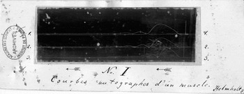
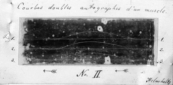
In order to place the curves “before the eyes of the Academy” Helmholtz had to transport them from Königsberg to Paris. Instead of sending the original glass cylinder, he used small adhesive transparencies made out of colle de possoin, or isinglass. By means of these sheets of isinglass –measuring ca. 9 cm in width and 3 cm in height – he stripped the upper layer of the soot together with the inscribed curves from the cylinder. Then he glued the isinglass sheets onto slightly bigger sheets of white cardboard paper and attached them to the manuscripts he sent off to the Academy (figs. 5 and 6).
“No. I. Autographic Curves of a Muscle.” On a strip of white cardboard paper, Helmholtz mounted the isinglass prints of his curves. Originally, the curves had been recorded on a rotating glass cylinder covered with soot. The glass cylinder was derived from a “champagne glass” and measured 3cm in diameter. The arrows below the pieces of isinglass indicate the reading direction for the curves. The contraction movement of the muscle is to be followed from right to left.

“Autographic double curves of a muscle.” This piece of isinglass has preserved the “print” of three double curves recorded on top of one another. Between the successive trials, Helmholtz had changed the position of the electrode on the nerve that caused the muscle to contract. Since all remaining factors were considered to remain constant, Helmholtz concluded that the lateral displacement in each pair of curves demonstrated the significant amount of time required for the stimulations to travel through the nerve. In other words, it is the empty space between the double curves that stands in for the physiological fact of nervous time.

In the nineteenth century, isinglass was produced mainly from cleaned and dried bladder skin of Kaluga and Beluga sturgeons. As already mentioned, the substance was used for a variety of purposes, e.g. the clarification of wine and beer, the production of glass or porcelain putty, and the manufacture of artificial pearls. Transformed into thin layers, isinglass was also used for copying images and the fabrication of “sharp casts” of coins. Lithographers and copper engravers applied this transparent surface that, in the German context, was also named “glue foil [Leimfolie]” or “glass paper [Glaspapier]” for fabricating reproductions of pictures. For this purpose, sheets of isinglass were first placed onto a drawing. With a needle, the engraver would then copy the drawing onto the isinglass. In the next step, graphite powder was rubbed into the needle traces. Finally, the entire film was lifted, reversed and pressed onto a polished stone or a copper plate, so that graphite traces were printed onto this surface and the etching could be started (Prechtl Reference Prechtl1835, 264; Anon. 1905, 96).
It is not clear how familiar Helmholtz was with this graphic technique that he briefly alluded to in the manuscript of the “Second Note.” However, he might have come across it when teaching anatomical drawing at the Kunstakademie in Berlin. At any rate, his use of isinglass was similarly graphic, when bringing his curves into transportable form: He applied the substance for producing “prints [Abdrücke]” (Kirsten et al. Reference Kirsten1986, 115) of curves that then were mounted onto white cardboard paper. As a result, the curves appeared as white lines against a black background.
Helmholtz captioned his curves. First he added a legend to the white cardboard paper. On the empty space below the isinglass sheets, he numbered the curves as “No. I” and “No. II.” In the margins right and left of the sheets he then noted “1., 2., 3.” as numbers referring to the individual curves that had been recorded on the respective pieces on top of each other (see figs. 5 and 6). Below the curves, Helmholtz then added arrows pointing from right to left as indicators for correctly “reading” the direction of the recorded phenomenon, i.e. the frog muscle contraction. In contrast to later uses of the graphic method, this direction still went against the grain of reading texts from left to right. Finally, the perhaps most important aspect was added. Helmholtz translated into words what was to be seen in the curves. For “No. I” he wrote “Autographic curves of a muscle,” for “No. II” he put “Autographic double curves of a muscle.” In the entire pile of manuscript materials concerning the “Second Note” this is the first time that it is a question of something “graphic,” not “drawn” or “traced.”
What does “autographic” mean? In the given context, the term can be understood, on the one hand, as “self written” – which, in the case of the frog, would be a rather remarkable expression. On the other hand, “autographic” can be read as “auto-recording,” similar to the expression “phonautograph” that Edouard-Léon Scott de Martinville introduced several years later with respect to the instrument he devised for registering sounds, noises, and speech. (Scott tried to fix the sounds of the human voice on glass plates covered with a “half-fluid substance” [see Scott Reference Scott1859, 314]). However, “autographic” can be also be taken as a reference to a procedure of fabricating facsimiles that was widely spread in the early nineteenth century. In the given case, the facsimile was not made by making use of paper and “autographic” ink, but on the basis of isinglass. Against this background, courbes autographes would translate into “curve print” or Kurvenabdruck.Footnote 20
As a final element, Helmholtz added his signature to the two pieces of cardboard paper. In both instances he wrote his name in the lower right corner of the papers, in order to highlight that they belonged to the written note that was equally signed “Helmholtz.” In a similar vein, he included another page with a written explanation concerning the curves, titled “Explanation of the examples [Explication des épreuves].” When publishing the “Second Note” in the Comptes rendus, this text was equally cut by the Academy.
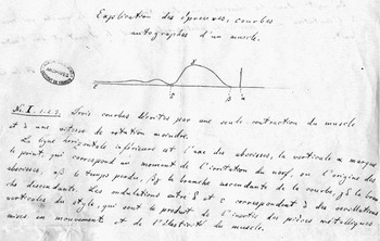
In this part of his manuscript, Helmholtz depicted the curves in schematized form (see fig. 7). The two drawings included in the “Explanation of the examples” do not show three curves on top of each other but restrict themselves to represent each one single curve in idealized form. However, Helmholtz kept with the somewhat unusual reading direction of the depicted muscle movement from right to left. At specific points he marked the idealized curve by way of Greek letters, checks, and dashes. At the same time, he extended the rather short legends from the cardboard paper. With respect to “No. I,” he noted: “Three curves that were described by a single contraction of the muscle and of a lower rotational speed” (Helmholtz Reference Helmholtz1851b, 1). This referred to the equally extended legend concerning “No. II,” in which Helmholtz explained that the rotation speed of the glass cylinder amounted to “six rotations per second.” However, besides the distance between the two places in which the nerve had been stimulated in successive trials, i.e. “55 mm,” this remained the only numerical value that the “Explanation of the examples” contained.
Excerpt from the addendum to the manuscript of Helmholtz's “Second Note.” In order to explain the curves he had sent to the Academy, Helmholtz added a one-page “Explanation of the examples.” By means of hand drawings he schematized the corresponding curves and marked the different phases of the recorded muscle contraction by means of Greek letters and other symbols. In the case of the simple contraction curves (see above, fig. 5), the text reads: “No. I. 1.2.3. Three curves described by a single contraction of the muscle and at a lower rotational speed [of the cylinder]. The lower horizontal line is the axis of abscissae, the vertical α marks the point that corresponds to the moment at which the nerve is stimulated or to the origin of the abscissae, αβ marks the time lost, βγ the ascending branch of the curve, and γδ the descending branch. The waves between δ and ɛ correspond to the vertical waves of the stylus, which are the product of the inertia of the metal pieces set in motion and the elasticity of the muscle.”

In a sense the schematization of curves in the “Explanation” had already started on the glass cylinder of Helmholtz's myograph. The drawing machine in Königsberg allowed for the curviform registering of muscle contractions. At the same time, however, the machine permitted the recording of horizontal and vertical lines. When no contraction was provoked and the stylus was put into touch with the rotating cylinder covered with soot, the myograph recorded a kind of base line. At the same time, the stylus registered a vertical line standing on this base line, when the muscle was stimulated to contract without the cylinder rotating. The text of the “Second Note” describes the horizontal lines as “abscissae” and, as a consequence, turns the vertical one into ordinates. In fact, the schematic curve drawings in the “Explanation,” with their vertical and horizontal frame lines, appear as being transferred into a segment of a coordinate system.
It is true that Helmholtz never attempted to give an algebraic formula for the shape of his “autographic curves.” Despite this fact, the mathematical connotations in this context are not accidental. They respond to Helmholtz's conviction that the phenomena of life can be investigated in scientifically appropriate ways, only if they are subjected to physico-mathematical treatment. One of the decisive features of this approach consisted in “representing oneself the causal connections of natural phenomena in terms of the mathematical image of dependence,” as du Bois-Reymond had repeatedly advocated since the late 1840s. However, in terms of representation the crucial elements for this image of dependence were not numbers. Rather, what was at stake was a representation according to the “image of a curve” that, in turn, was based on “calculated and observed numerical values” (du Bois-Reymond Reference Du Bois-Reymond1848, xxvi-xxix).
One of the explicit models for this understanding of curve images in the emerging field of experimental physiology, was provided by the work of the Belgian statistician and proto-sociologist Adolphe Quetelet. In his book Sur l’homme ([1836] Reference Quetelet and Knox1842), Quetelet documented the dependence of “literary talent on age” first by means of numbers and then by means of striking curve images. In other words, when du Bois-Reymond talked in 1848 about the “method of curves,” he did not refer to the laboratory practice of using instruments that allow for the self-recording of physiological phenomena. Rather, the “method of curves” functioned as a theoretical instrument, a pictorial tool that illustrated the relation of an “observed effect” to “several variable circumstances” in convincing ways. In other words, it makes clearly visible the relation between dependent and independent variables.Footnote 21
Despite the fact that Helmholtz, with his curves, is far from representing numerical values, his schematic hand drawings in the “Explanation of the examples” do come close to this mathematical understanding of curves. What Helmholtz's curves actually represent is the dependence of an observed effect – i.e. the contraction of a frog muscle – from changing circumstances – i.e. the length of the nerve (or, to be more precise, the varying distance of stimulations points with respect to the muscle) and therefore the time required for the propagation of stimulations in the nerve. Insofar as this dependence had already been observed (and precisely measured) by Helmholtz's use of the Pouillet method in 1850, one could say that his curve recordings from 1851 only convey known facts by means of a new method of representation. In other words, what Helmholtz's curves depict are neither precise measurements nor numerical results, but the fact of physiological time.
In this context, isinglass provides the tangible link between text and technology. Given the semiotic status of Helmholtz's curve examples as Abdrücke, i.e. indexical signs, one could almost speak of fingerprints produced by his experimental set up.Footnote 22 A remarkably organic inscription surface, his isinglass sheets lead us from the paper manuscripts preserved in the archives of the Academy of Science in Paris back to the tables and instruments that Helmholtz, in his laboratory room at Königsberg university, had assembled in order to perform innovative timing experiments: the glass cylinder, the stylus, the steel frame, etc.
However, the original curve recordings do not just bring us close to the technological components of Helmholtz's experimental set up. At the same time, they confront us with its organic elements. Following the transparent sheets of isinglass, we thus arrive, on one side of Helmholtz's drawing machine, at the frogs, the calf muscles of which were hung on a steel frame in such a way that their contractions would scratch traces into the soot covering the rotating glass cylinder. On the other side of his drawing machine, i.e. the isinglass side, we encounter sturgeons, the swim bladders of which had been cleaned, dried, ground, and then moistened again, in order to be able to receive soot traces and to transfer them from cylindrical form to the flatness of cardboard paper.
It was this rather surprising encounter between frogs and sturgeons on a laboratory bench in Königsberg, and a highly sophisticated transmission assemblage inserted between these organisms, that opened up the possibility for transferring Helmholtz's curves as curves to the pile of manuscripts that up until today belongs to the published version of the “Second Note.”
However, the curves do not just refer us back to the heterogeneous drawing machine that Helmholtz had devised in order to better illustrate his earlier experiments on the propagation velocity of nervous stimulations. They lead us even further. The material connection between the “Second Note” and the experimental set-up does not stop in Königsberg, as it were. From there the rotating cylinder derived from a champagne glass and the isinglass sheets obtained from Beluga sturgeons that, at the same time, functioned as the central source of caviar, the material semiotic trace of Helmholtz's experiments bring us close to the Caspian Sea. As a result, these experiments are not only inserted into a technological context dominated by telegraphy and electromagnetism. They are also embedded in a cultural and natural landscape.
It is unclear why the final paragraph of the “Second Note,” the curve images, and the corresponding text of the “Explanation of the examples,” were not published in the Comptes rendus. It is also unclear if this editing was done with Helmholtz's consent. However, the ultimate reason for the omission is probably rather simple. In the 1850s, the Comptes rendus was not prepared to reproduce any figures. The journal did print geometrical schemes and mathematical symbols as important elements of the contributions it published. The Academy changed this policy thirty years later. Interestingly enough, the occasion was provided by another study concerning physiology and time, Etienne Jules Marey's chronophotographs obtained from the movements of a walking man and a running horse (Marey Reference Marey1882; see also Crosland Reference Crosland1992, 258).Footnote 23
In the early 1850s, these kinds of reproductions were technically difficult to handle, and usually drawings and other illustrations were presented on extra tables placed at the end of the corresponding journal volume. Helmholtz must have been aware of this state of affairs, given the fact that the “Second Note” was his second publication in the Comptes rendus. Despite this fact he added two examples of original curves to his submitted manuscript, probably meant for convincing the present members of the Academy of the visual force implied in his new method. It also remains unclear if the members of the Academy that convened during its session of September 1, 1851, actually looked at Helmholtz's curves and if the corresponding text of “Explanation of the examples” was communicated to this audience.
Be this as it may, one week after the presentation of Helmholtz's “Second Note,” a commission was established to study his time experiments more closely. After an initial evaluation process had led to accepting the “Second Note” for print, an extended review was meant to evaluate the conclusions and implications that were tied to the article in question. Besides two leading physiologists, François Magendie and Pierre Flourens, the physicist Claude Pouillet was also named as member of the commission. However, the report of this commission was never published. During the period in question Magendie seems to have been very busy, not just inside the Academy where he was working for numerous commissions, but also outside of it – in particular in terms of promoting his former assistant, Claude Bernard. In 1848, Bernard had finally made significant progress in his experimental work. Magendie was firmly convinced that Bernard's studies were able to impact significantly on the development of experimental physiology in France. Hence, he engaged himself extensively in promoting Bernard (Holmes Reference Holmes2004, 29–33).
In a similar vein, Pouillet did not actively contribute to evaluating the implications of the “Second Note.” The reason might have been that Helmholtz, who initially had applied the basic principle of Pouillet's timing method in his experiments with much success, criticized the same method in the “Second Note” as rather complicated and time consuming. Only Flourens remained. In fact, he was the only member of the commission that acted. At least, he noted on the first manuscript page of the “Second Note” the French word “vu,” i.e. “seen” – which does not necessarily mean that he had read the texts and attentively looked at corresponding curve images. At any rate, shortly after the “Second Note” had been published, both elements – the text and the images – were filed in the archives of the Academy of Science.
Against this background it seems that both of Helmholtz's articles concerning his measurement of physiological time were failures. In early 1850, the telegraphic style of the “Preliminary Report” was very hard to understand. Even du Bois-Reymond's clarified French version of this report, published in the Comptes rendus in February 1850, was met with considerable reluctance and raised many objections – up to the point that Helmholtz was taken to be a ‘mad man.’ No doubt Helmholtz's second article, the “Second Note” from 1851, was much easier to understand. However, it failed to be printed in its entirety. In a sense, then, both articles remained hieroglyphs – similar to the engravings on a whale's body.
Epilogue
One year after the “Second Note,” Helmholtz published an extensive presentation of his “new method” in German. Referring back to the 90-page article of 1850, Müller's Archiv für Anatomie, Physiologie und wissenschaftliche Medicin presented the new piece under the title “Measurements Concerning the Propagation Speed of Stimulations in the Nerves (Second Series)” (Helmholtz Reference Helmholtz1852). With its 17 pages, this text is significantly longer than the “Second Note.” In addition, the German version was published along with figures printed on tables placed at the end of the corresponding volume.
These figures show the details of Helmholtz's construction of the myograph (see above, fig. 4) and a series of four idealized drawings of exemplary curves and double curves – this time adopting the usual reading direction from left to right. It is striking that these curve images continue to lack precise indications with respect to the timing of the recorded phenomena.
Despite its title, Helmholtz's article discusses the measuring of time in only marginal ways. The beginning of the curve discussions makes this quite evident. Helmholtz explicitly introduces the curves not as a means for measuring but as a tool for “representing [darstellen] the propagation speed in the nerve” (Helmholtz Reference Helmholtz1852, 211).
Accordingly, the issue of measurement remains in the background of the text. In this respect, Helmholtz states in an almost casual manner: “As far as the absolute value of the propagation speed is concerned, the horizontal distances of the two curves cannot be measured with very great precision.” In a similar casual fashion, he then adds that the values obtained by means of the new method were “about as [ungefähr] great” as in the use of the Pouillet method (Helmholtz Reference Helmholtz1852, 215).
The basis for this statement was the manual measuring of the curves, taking into account the circumference of the cylinder (85.7 millimeters) and its number of rotations. One millimeter of length in the curve drawing corresponded to 1/514 of a second. If, then, one also took into account the distance between the two places in which the nerve was stimulated when recording the contractions, i.e. 53 millimeters, one could deduce the propagation speed of the stimulation in the nerve, in the present case 27.25 meters per second. Helmholtz does not comment on the reliability of this result. Similar to the “Second Note,” the given number remains juxtaposed to the results of his earlier measurements with the Pouillet method without further explanation. Helmholtz restricts himself to reminding the reader of the final result of the “Measurements” he had conducted two years earlier: “The most probable value in the earlier experiments was 26.4 meters [per second]” (Helmholtz Reference Helmholtz1852, 216).
Helmholtz's reproductions of the curves made history. In the following years, their iconography was taken up by eminent experimentalists investigating the physiology of time. Hermann Munk (Reference Munk1860), Franciscus Donders (Reference Donders1868), and Etienne Jules Marey (Reference Marey1868), in particular, were inspired by Helmholtz's tracings. They referred to and reproduced these images, but also transformed and expanded on them. Following a suggestion of Helmholtz's former student Rudolf Schelske (Reference Schelske1864, 161), Donders and Marey attempted to increase the timing function of the curves by registering temporal signals parallel to the muscle phenomena they recorded. Thus Marey, in 1878, in his famous book, La méthode graphique, reproduced the image of a double curve for measuring the speed of the nervous agent that, on the same recording sheet, showed the simultaneous recording of the traces produced by a vibrating tuning fork at a precisely determined pitch (Marey Reference Marey1878, 147). At this point, Helmholtz's early objection that the friction of the graphic recording process slows down the recorded phenomenon obviously no longer played any role.
Today we remain fascinated with the images of these curves. Numerous exhibitions have staged the superb aesthetics of the curve drawings produced by Donders, Marey, and other physiologists in the lab (see, for example, Frizot Reference Frizot and Hultén1977; Mannoni Reference Mannoni1999, Didi-Huberman and Mannoni Reference Didi-Huberman and Mannoni2004; Amelunxen, Appelt, and Weibel Reference Amelunxen, Appelt and Weibel2008). In these contexts, however, the materiality of the inscription surfaces had not attracted significant attention. It seems as if the isinglass that Helmholtz relied on to produce authentic prints of his myographic curve drawings had simply been replaced by ordinary paper. In fact, Etienne-Jules Marey, Carl Ludwig, Angelo Mosso, and other physiologists used paper as an inscription material when making use of the graphic method – be it white paper that was written upon by styluses filled with ink, or be it blackened paper in which sharpened steel styluses would scratch white traces.
However, rotating paper is only part of the truth. Muscle and nerve physiologists of the late nineteenth century also made use of swinging glass plates when it came to recording organic movements with high velocities. Faced with strikingly diverging time results in Schelske, Donders, and other physiologists, Helmholtz returned to the issue of the physiological time in humans in the late 1860s. In the context of his new experiments on the matter, Helmholtz used glass plates as inscription surfaces. Isinglass and glass cylinders were no longer on his mind – or his laboratory bench. By the same token, Helmholtz turned away from his ingenious myograph with rotating cylinder and adopted a recently modified version of this device, a so-called “pendulum myograph.” At this point in time, the version of the myograph initially suggested by Helmholtz was dismissed as “rather complicated and expensive” (du Bois-Reymond Reference Du Bois-Reymond1866, 583).
Since the early 1860s, physiologists such as Adolf Fick, Emil Harless, and Ludwig Thiry had contributed, in different ways, to improving the construction of Helmholtz's myograph. In part, these improvements concerned the determinination of the number of rotations made by the glass cylinder, but primarily they consisted of replacing the rotating glass cylinder by a glass plate that, similar to a pendulum, moved past the styluses with great speed (Fick, Reference Fick1862; Harless Reference Harless1863; Thiry Reference Thiry1864).
The reason for Helmholtz's decision to adopt the new version of the myograph was indeed the greater precision of this instrument. As he explained, he had ordered the construction of a pendulum myograph in order to “elevate the [graphic] method to utmost precision” (Helmholtz Reference Helmholtz1870, 184). The instrument in question consisted “essentially of a heavy and solid iron pendulum the oscillation of which took almost two seconds, and which at its lower end carries a rectangular plane glass plate [Glastafel] on which contraction curves are inscribed” (Helmholtz Reference Helmholtz1870, 184–185).
Using this new instrument, Helmholtz and his assistant Nicolai Baxt conducted time measurements concerning the propagation speed of stimulations in human motor nerves. The final results of these experiments were communicated in 1870 to the Academy of Science in Berlin. However, this publication does not contain any curve images. Apparently it was sufficient to have reached, by means of the curves, what was considered as precision time measurements. Helmholtz's article presented all of his results by way of numbers arranged in tables. The curves had only functioned as a means to achieve them.
There is another reason why Helmholtz turned away from the initial form of the myograph. Physiologists had raised objections against the use of isinglass as an inscription and storage medium for curve tracings. As Otto Funke explained in a talk at the Royal-Saxon Society of Science, the traditional “detaching” of curve recordings from the glass cylinder by means of “gelatin,” e.g. isinglass, had the disadvantage that “the copy was not entirely sharp and clear; that it is impossible to add any retrospective descriptions of single parts of the curve onto the gelantin paper; that occasionally distortions arise during the drying of the moistened gelantin paper” (Funke Reference Funke1860, 65).
A leviathan seems to have been caught by the crew working on the ship of physiology. Around 1850 the inner skin of a sea monster had made it possible to produce the first authentic prints of myographic curves recorded on a glass cylinder that were so flat and light that they could be attached to a manuscript destined for an Academy. Ten years later, glass plates allowed for a different but equally seamless transmission from the world of lab recordings to the world of printed paper. As Funke explained, all one had to do was to place the glass plate “unremovably” onto sensitive silver paper and expose it to sunlight. The result was “flawless photographs” of the curves (Funke Reference Funke1860, 65). In fact, in the years to come, the reproduction of curve drawings and other traces by means of photography altered the scientific practice of physiological research in significant ways. This, however, would be another chapter from the semaphorological history of inscriptions in which the technological and the biological, the artificial and the natural combined and contrasted with one another in often surprising ways.
Acknowledgments
This paper rereads and reconsiders findings initially presented in my book Die Helmholtz-Kurven (Schmidgen Reference Schmidgen2009). The English translation of this book was prepared and published while the present paper was under review (Schmidgen Reference Schmidgen and Schott2014). In its concrete form, it is based on two presentations. The first was a contribution to the conference “Membranes, Surfaces, Boundaries. Interstices in the History of Science, Technology, and Culture,” organized by Mathias Grote, Laura Otis, and Max Stadler and held at Max Planck Institute for the History of Science Berlin from October 7–9, 2010. The second talk was given at the Annual Meeting of the History of Science in Montréal on November 5, 2010. I am thankful for the comments and criticism I received on these occasions. Thanks also to the reviewers of this paper and their valuable suggestions for improving it. Finally, I would like to thank Travis Gaug (Regensburg) for his help in establishing the English version of this paper. Unless otherwise stated all translations from the German and the French are my own.