
I. INTRODUCTION
The rectangular waveguide tubes have been extensively used in the fields of radar, satellite, electronic antagonism as well as space communication as a result of meeting the smooth dispersion characteristics, broad bandwidth and less signal loss. Reference Liu, Han, Liu, Zhang and Lu1,Reference Xue, Meng, Wang, Li and Liu2 The rotary draw bending (RDB) process has become one of most common ways to bend tubes due to the merits of high precision, high efficiency, and cost-effective. Reference Zhao, Liu and Yang3 However, owing to the structural features of thin-wall and hollowness for rectangular waveguide tube, the cross-sectional deformation occurs inevitably in RDB process, which not only decreases the geometric accuracy, but also seriously influences the microwave transmission efficiency. Reference Li and Zhang4 When different waveguide materials are used, such as widely used 3A21 aluminum alloy and H96 brass, the mechanical behaviors of rectangular waveguide tube during RDB process will make a difference, which not only influences its stress/strain distribution characteristics in forming process but also determines its ability to resist the cross-sectional deformation. So exploring the cross-sectional deformation behavior of rectangular waveguide tube with different materials in bending has become an important issue for further realizing tube material selection of rectangular waveguide and the improvement of product quality.
Over the years, a number of researches about the cross-sectional deformation of rectangular tube with different materials in bending process have been conducted through various methods. Paulsen and Welo Reference Paulsen and Welo5 experimentally investigated the cross-sectional deformation of aluminum alloy rectangular tube in pure bending and pointed out that distinct strain hardening characteristics obtained by different heat treatments have a large effect on the onset of buckling and the magnitude of cross-sectional deformation. Analytical models to predict cross-sectional deformation had also been developed by Paulsen and Welo, Reference Paulsen and Welo6 they concluded that plastic anisotropy has the most vital influence on the suck-in of the outer flange for rectangular tube. On the basis of finite element models (FEM), Chen et al. Reference Chen, Peng and Yuan7 and Wei et al. Reference Wei, Zhong and Song8 researched the cross-sectional deformation behavior of different types of aluminum alloy rectangular tubes in multipoint stretch bending and discrete die bending, respectively, and both drew the conclusion that the increase of yield strength results in the decrease in cross-sectional deformation. Based on energy minimization, Zhu et al. Reference Zhu and Stelson9 derived the expressions of the distortion amount for rectangular tube in stretch bending and found that the distortion is independent of material properties. Chen and Masuda Reference Chen and Masuda10 found that the relation between cross-sectional deformation and bending curvature for square tube subjected to plastic pure bending is particularly influenced by the yield stress and hardening exponent. Clausen et al. Reference Clausen, Hopperstad and Langseth11 experimentally investigated the effect of material, bending radius and wall thickness on the cross-sectional deformation of aluminum extrusions in stretch bending. By using the methods of experiment and finite element (FE) analysis, Li et al. Reference Li, Liu, Yang and Zhang12 studied the mechanical behavior of high-strength concrete filled high-strength square steel tube under pure bending and found that the ultimate bearing capacity of tube increases with the steel yield strength. Hamano et al. Reference Hamano and Watari13 studied the effect of material properties on cross-sectional deformation of aluminum alloy square tube in push-through bending, and indicated that materials with higher yield strength show greater cross-sectional deformation. While most studies related to the cross-sectional deformation of rectangular tube merely adopted different types of aluminum alloy tube materials and the material parameters of them could not represent other kinds of distinguishing materials. Some conclusions were obtained through purely theoretical analysis, difficult to be verified by means of real existing materials. Moreover, these research above basically concentrated on pure bending and stretch bending process, less aimed at the RDB process.
In view of the RDB process of rectangular tube, Utsumi et al. Reference Utsumi and Sakaki14 studied the effect of containing a center rib on forming quality by using two types of aluminum extruded square tubes. Zhu et al. Reference Zhu, Liu and Yang15 investigated the sensitivity of springback and section deformation to process parameters for thin-walled rectangular tube but did not consider the influence of material parameters in this study. Zhang et al. Reference Zhang, Liu, Zhao and Yang16 pointed out that the cross-sectional deformation of rectangular tube in bending process increases evidently with the decrease of initial yield stress and strength coefficient. Based on global sensitivity analysis system, Dong et al. Reference Dong, Liu and Yang17 carried out the sensitivity of coupling effect of material parameters to cross-sectional deformation of rectangular tube after retracting mandrel, they found that the sensitivity values of coupling groups to cross-sectional deformation are larger than those of one-parameter groups. However, the research above almost adopted virtual material parameter variation of certain material, which actually had large discrepancy with parameters of real material.
Therefore, widely used 3A21 aluminum alloy and H96 brass rectangular waveguide tubes were taken as research objects in this article, and under ABAQUS platform, the three-dimensional finite element (3D FE) models of RDB process for 3A21 and H96 tubes were established and validated by experiment. To study the cross-sectional deformation behaviors of rectangular waveguide tube with different materials in RDB, the cross-sectional deformation for 3A21 and H96 tubes with and without mandrel was carried out, respectively, and the material parameters which remarkably influenced the cross-sectional deformation were explored, which will provide a powerful reference for the choice of material in terms of rectangular waveguide tube.
II. DESCRIPTION OF CROSS-SECTIONAL DEFORMATION AND SELECTION OF CHARACTERISTIC SECTIONS ALONG BENDING DIRECTION
With the purpose of quantitatively studying the cross-sectional deformation behavior of rectangular waveguide tube in RDB, the deformation in height and width directions of rectangular tube can be described by Eqs. (1)–(2). Reference Zhang, Liu, Zhao and Yang16
 $${\delta _h} = {{h - {h_{\min }}} \over h} \times 100\% \quad ,$$
 $${\delta _b} = {{{b_{\max }} - b} \over b} \times 100\% \quad ,$$
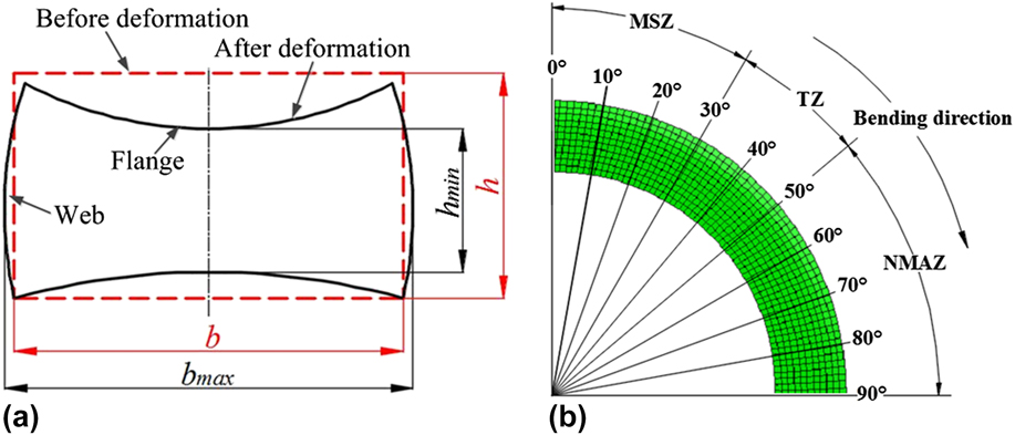
where δ h and δ b are the maximum height and width deformation ratios in a certain section, respectively. h and b are the height and width of the tube before deformation, respectively; h min and b max are the minimum height and the maximum width of the tube after deformation, respectively, as shown in Fig. 1(a).
The measurement of cross-sectional deformation of rectangular tube in RDB: (a) the cross section before and after deformation and (b) the distribution of characteristic sections along bending direction.
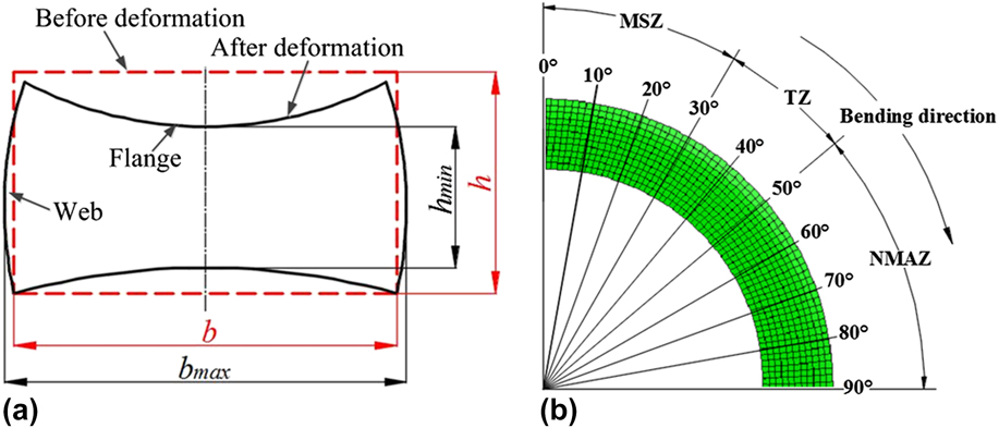
To systematically reflect the cross-sectional deformation of rectangular waveguide tube during RDB along bending direction, taking a tube with the bending angle of 90° as the target, ten characteristic sections have been selected, as shown in Fig. 1(b). Meanwhile, the section 90° is near the clamp die side, namely the initial bending section, and the section 0° is near the pressure die side, namely the final bending section. When a mandrel is used, the whole bending deformation zone of rectangular waveguide tube is composed of mandrel support zone (MSZ), transition zone (TZ), and no mandrel affect zone (NMAZ). Simulation results show that the mandrel directly supports the range from 0° to 30°, so the MSZ is from 0° to 30°. While for the TZ, the accurate range of it can not be observed easily before the study, so the range of TZ is defined vaguely to be from 30° to 50°. The NMAZ is from 50° to 90°.
III. THE ESTABLISHMENT OF 3D FE MODELS OF RDB PROCESS FOR RECTANGULAR WAVEGUIDE TUBE AND EXPERIMENTAL VERIFICATION
A. The establishment of 3D FE models
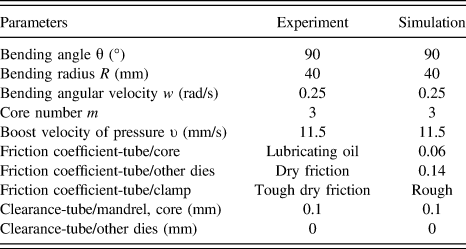
The whole RDB process of rectangular waveguide tube when a mandrel is used includes bending, retracting mandrel, and springback. The rectangular waveguide tube with the geometrical dimension of 24.86(b) × 12.20(h) × 1(t) mm was defined as the deformable body, which was described as the 4-node doubly curved thin shell elements S4R due to its merits of reduced integration and hourglass control. The dies composed of bending die, pressure die, clamp die, wiper die and mandrel-cores were totally modeled as the discrete rigid bodies using the 4-node 3D bilinear quadrilateral rigid element R3D4. Taking the tradeoff between simulation accuracy and efficiency into consideration, the sizes of mesh for both the rectangular tube and mandrel-cores were 1 × 1 mm, and other dies were all meshed 3 × 3 mm. The classical Coulomb friction model was adopted to describe the friction behaviors between tube and dies, the “surface-to-surface contact” type was used as the contact condition, and the penalty contact method was chosen as the contact algorithms between tube and dies. Other simulative conditions are shown in Table I. Two different materials of rectangular waveguide tube, 3A21 aluminum alloy and H96 brass, were taken as the research objectives here, which were both assumed as homogeneous and isotropic materials that conformed to Von Mises yield criterion. The power exponent hardening model was selected to describe the hardening behavior of tube materials, as shown in Eq. (3).
 $$\sigma = K{\left( {{\varepsilon _0} + \varepsilon } \right)^n}$$
Simulative and experimental conditions in RDB process of rectangular waveguide tube.

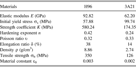
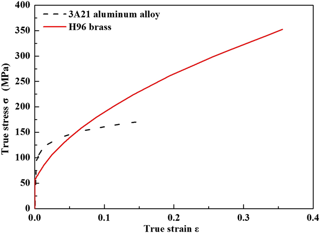
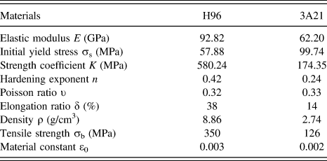
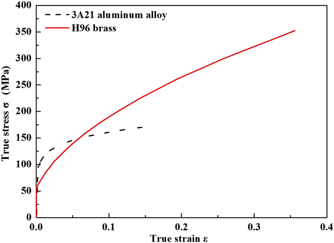
Table II shows the mechanical properties of 3A21 and H96 tubes, which were obtained by uniaxial tensile test, and the true stress–strain curves of both tubes are shown in Fig. 2.
Property parameters of 3A21 aluminum alloy and H96 brass rectangular tubes.
The true stress–strain curves of 3A21 aluminum alloy and H96 brass tubes.
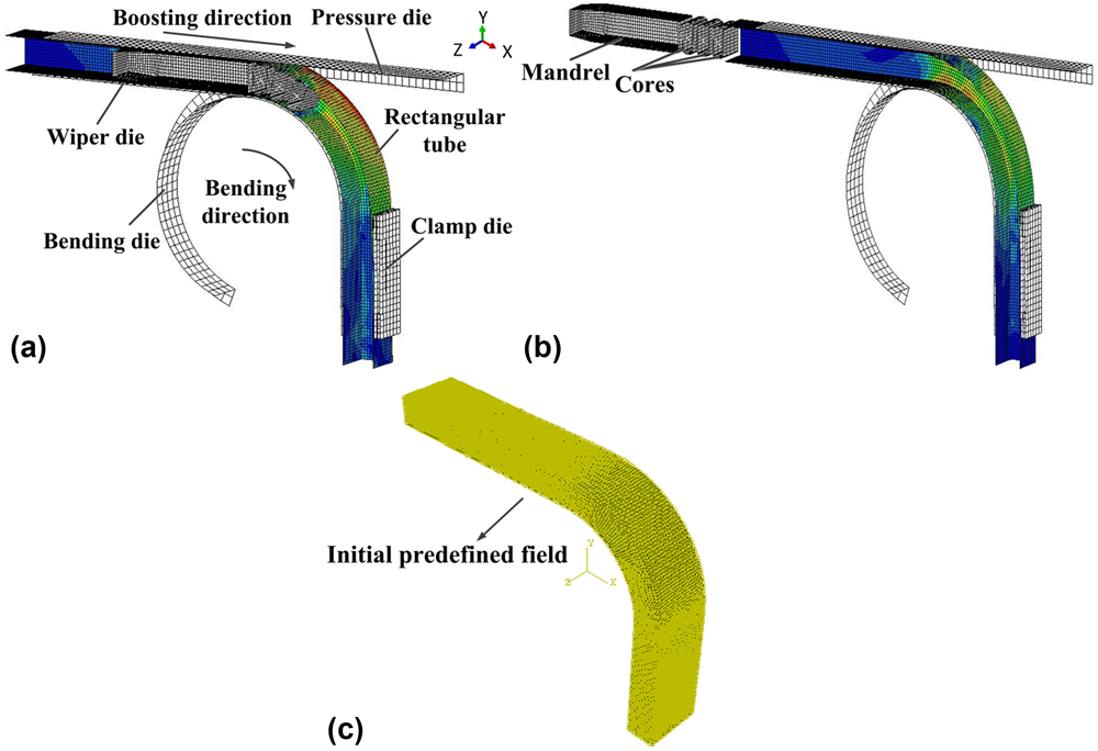
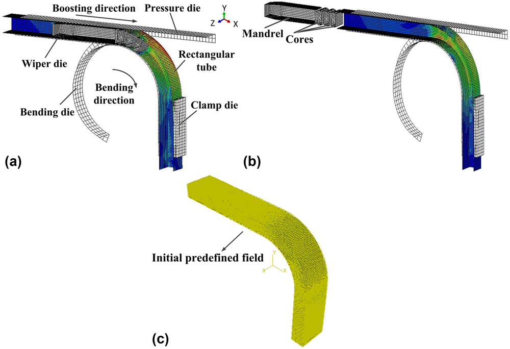
On the basis of the resolved key modeling techniques above and ABAQUS/Explicit platform, 3D FE model of bending for rectangular waveguide tube was established, as shown in Fig. 3(a). After imposing a retracting mandrel velocity which was opposite to the boosting direction on the mandrel-cores, 3D FE model of retracting mandrel for rectangular waveguide tube was built, as shown in Fig. 3(b). As importing the output files of the results from the retracting mandrel process into ABAQUS/Standard software, and applying a fixed boundary to the end of tube, a springback model of rectangular waveguide tube was also built, as shown in Fig. 3(c).
3D FE models of rectangular waveguide tube: (a) bending, (b) retracting mandrel, and (c) springback process.
B. Experimental verification of 3D FE models
With the purpose of verifying the reliability of 3D FE models of RDB process of rectangular waveguide tube, the experimental conditions were kept consistent with the simulative ones, as shown in Table I.
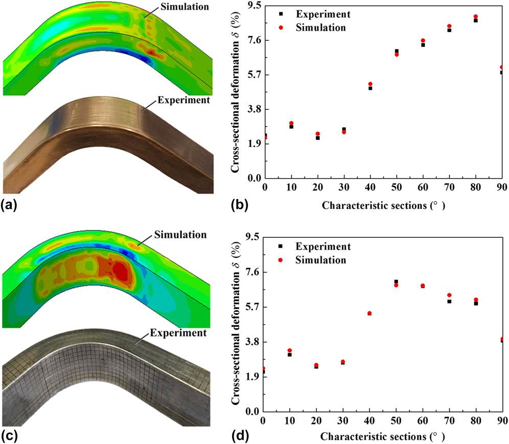
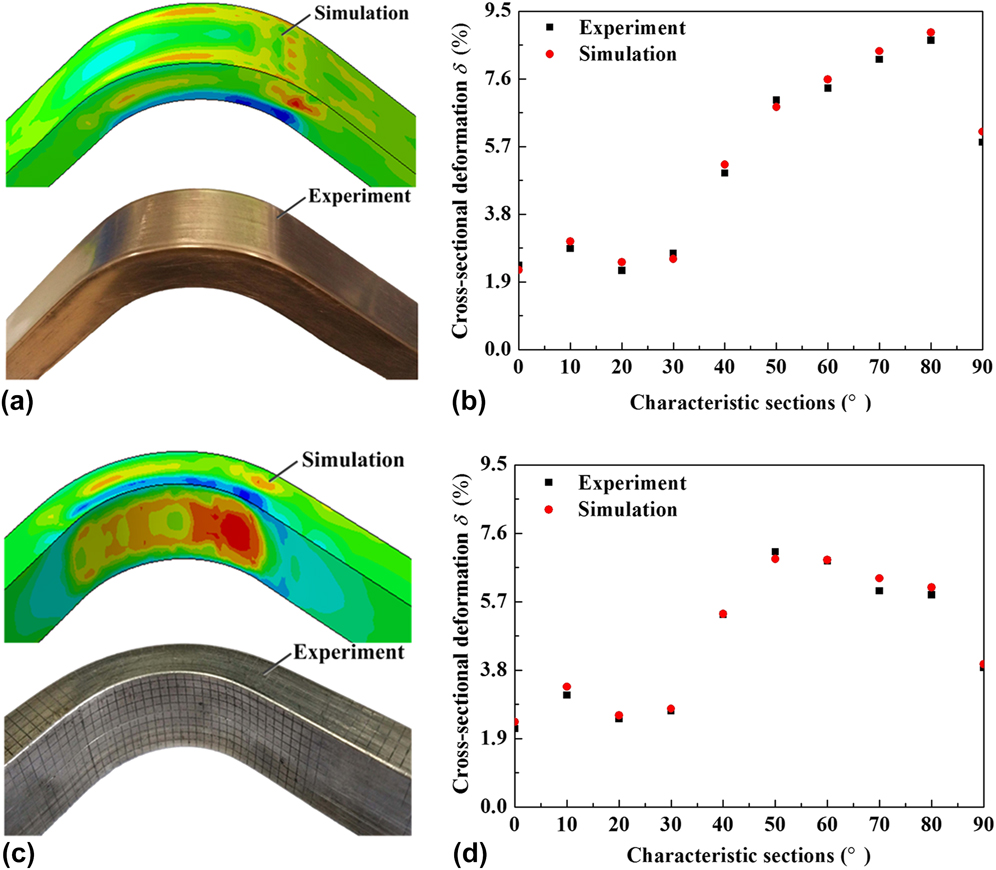
Figure 4 shows the simulative and experimental results of RDB process of rectangular waveguide tube with mandrel using H96 brass and 3A21 aluminum alloy tubes, respectively. It can be seen from Figs. 4(a) and 4(c) that the simulative results of both tubes agree well with the experimental ones, and relatively good forming parts are obtained. As shown in Figs. 4(b) and 4(d) in which the simulative results of the maximum height deformation in 10 characteristic sections [0°, 10°,…, 90°, as shown in Fig. 1(b)] are compared with the experimental ones for H96 and 3A21 tubes, respectively, it can be found that for both tubes, the changing tendencies of simulative and experimental results are similar on the whole, and the maximum relative errors between the simulative and experimental results for H96 and 3A21 tubes are 10.4% and 8.5%, respectively. After the qualitative and quantitative analyses, it can be concluded that the 3D FE models of RDB process of H96 brass and 3A21 aluminum alloy rectangular waveguide tubes are effective and reliable.
The simulative and experimental results of RDB process of H96 brass and 3A21 aluminum alloy rectangular waveguide tubes with mandrel: (a) the profile of forming part for H96 bent tube, (b) the maximum height deformation of H96 tube along bending direction, (c) the profile of forming part for 3A21 bent tube, and (d) the maximum height deformation of 3A21 tube along bending direction.
IV. RESULTS AND DISCUSSION
A. Cross-sectional deformation of 3A21 and H96 rectangular tubes in characteristic cross section
1. Cross-sectional deformation of rectangular tube in characteristic cross section without mandrel
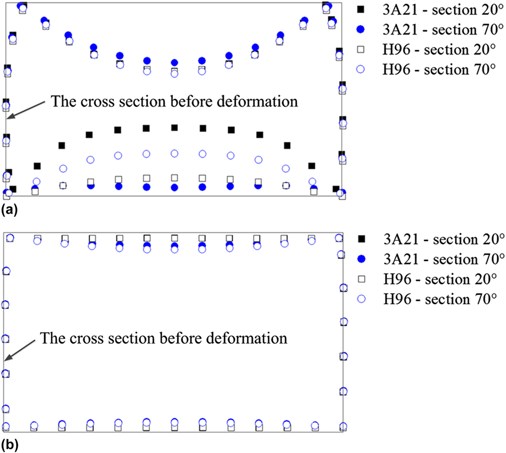
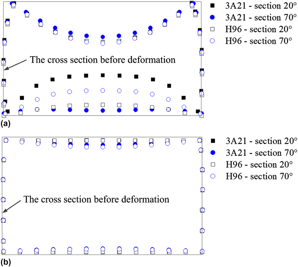
To analyze the cross-sectional deformation of 3A21 and H96 tubes in characteristic cross section without mandrel, sections 20° and 70° are separately selected, which generally reflect the deformation of the whole tube. Figure 5(a) shows the deformation diagram of the characteristic sections 20° and 70° without mandrel using 3A21 and H96 tubes, respectively. It is shown that both the inner and outer flanges of the characteristic section all sag seriously, but the bulging of two webs is relatively small, which illustrates that without mandrel, the deformation in height direction δ h is sufficient to indicate the cross-sectional deformation δ of rectangular bent tube in characteristic section. In addition, in outer flange of rectangular tube, the deformation amount for 3A21 and H96 tubes in sections 20° and 70° has no large difference, while in inner flange, the deformation amount for both tubes in different sections is not always consistent, that is, the deformation of 3A21 tube in section 20° is higher than that of H96 ones, it reverses in section 70°. Thus, it can be concluded that when no mandrel is used, the material has little influence on the sagging of outer flange for rectangular tube, but mainly affects the deformation of inner flange.
Deformation of characteristic sections 20° and 70°: (a) without mandrel and (b) with mandrel.
2. Cross-sectional deformation of rectangular tube in characteristic cross section with mandrel
To analyze the cross-sectional deformation of 3A21 and H96 tubes in characteristic cross section with mandrel, section 20° in MSZ and section 70° in NMAZ are chosen, respectively. Figure 5(b) shows the deformation diagram of the characteristic sections 20° and 70° of 3A21 and H96 tubes after bending with mandrel. It can also be found that whether in section 20° or section 70°, the cross-sectional deformation in width direction is small enough to be neglected compared with that in height direction for both tubes. Moreover, due to the support of mandrel-cores in section 20°, the sagging of inner and outer flanges for both tubes appears to be identical. While in section 70°, there is little difference in the sagging of inner flange for both tubes, and the deformation of outer flange for H96 tube is larger than that for 3A21 ones. Therefore, when a mandrel is used, the influence of material on deformation of outer flange in NMAZ is greater than that on deformation of inner flange.
B. Cross-sectional deformation of 3A21 and H96 rectangular tubes along bending direction
1. Cross-sectional deformation of rectangular tube along bending direction without mandrel
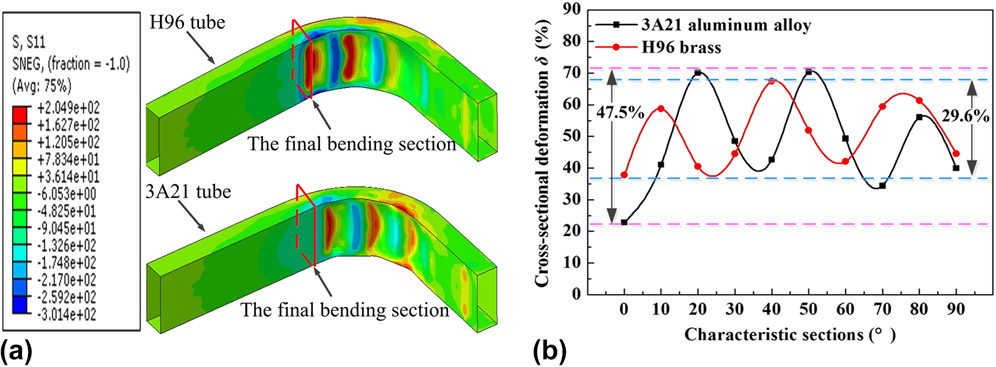
Figure 6 shows the tangential stress distribution and cross-sectional deformation of 3A21 and H96 rectangular tubes along bending direction in RDB process without mandrel. It can be seen from Fig. 6(a) that wrinkle phenomenon, which belongs to large section deformation, occurs obviously in inner flange of both tubes, and the position of wrinkle initiation for H96 tube is more close to the final bending section than that for 3A21 ones. Plastic deformation will occur in an instant at which stress in inner flange reaches the initial yield stress. The initial yield stress of H96 tube is smaller than that of 3A21 ones, thus under coincident bending condition, the yield phenomenon of H96 tube begins earlier. Moreover, owing to no mandrel support, the stiffness of the tube decreases instantaneously in bending, and the decrease in stiffness makes wrinkling occur more easily.
The tangential stress distribution and cross-sectional deformation of 3A21 and H96 rectangular tubes along bending direction in RDB process without mandrel: (a) the tangential stress distribution and (b) the cross-sectional deformation.

To quantitatively analyze the cross-sectional deformation of 3A21 and H96 tubes in RDB process without mandrel, Fig. 6(b) shows the distribution laws of cross-sectional deformation of both tubes along bending direction. It can be observed that the minimum cross-sectional deformation ratio of 3A21 and H96 tubes even exceeds 20%, indicating that the cross-sectional deformation of both tubes is serious. In addition, the fluctuation ranges of cross-sectional deformation of 3A21 and H96 tubes along bending direction are 47.5% and 29.6%, respectively, which reveals that the collapse of 3A21 tube is more severe and the cross-sectional deformation of 3A21 tube along bending direction distributes more inhomogeneous. When deformation enters the plastic range, a smaller hardening exponent probably makes the strain concentration and large local deformation occur more easily. Reference Paulsen and Welo5 Therefore, the main reason is that the hardening exponent of 3A21 tube is far smaller than that of H96 ones, making its cross-sectional deformation along bending direction more uneven. It can also be seen from Fig. 6(b) that the position of initiating wrinkle for H96 tube is nearer to section 0° compared with that for 3A21 tube, and the interval of initial wrinkling for both tubes is about 10°, which further proves the phenomenon in Fig. 6(a).
2. Cross-sectional deformation of rectangular tube along bending direction with mandrel
a. Cross-sectional deformation of 3A21 and H96 tubes after bending process
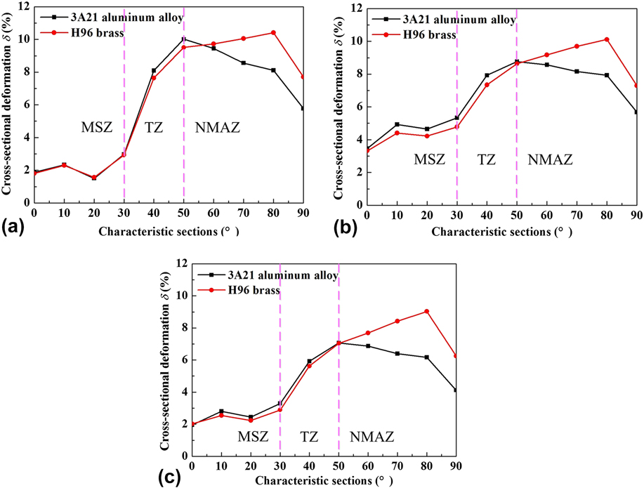
Figure 7 shows the distribution laws of cross-sectional deformation for 3A21 and H96 tubes along bending direction after bending, retracting mandrel and springback process. It can be seen from Fig. 7(a) that after bending process, in MSZ, the curve of cross-sectional deformation fluctuates within a small range, and the deformation magnitude for 3A21 tube is nearly in coincidence with that for H96 ones. Hence, it can be concluded that the cross-sectional deformation in MSZ is uniform and the effect of material on cross-sectional deformation is little here.
The distribution of cross-sectional deformation for 3A21 and H96 tubes along bending direction: (a) after bending process, (b) after retracting mandrel process, and (c) after springback process.
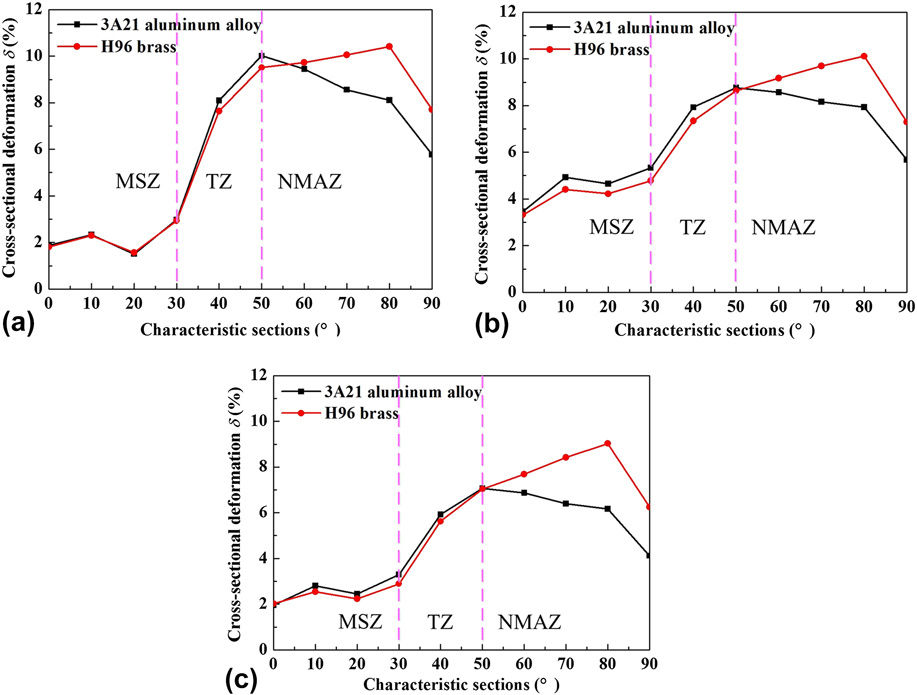
In TZ, the cross-sectional deformation of 3A21 tube is larger than that of H96 ones. Due to locating in a transition region adjacent to MSZ, the deformation here is synthetically affected by both mandrel and material, so the deformation here is a result of multifactors influence. While in NMAZ, the deformation of both tubes reverses. According to Eq. (3), it can be found that strength coefficient K and hardening exponent n of material both largely decide the magnitude of stress value, so the main reason is that strength coefficient K and hardening exponent n of H96 tube material are larger than that of 3A21 ones, and under the same deformation condition, the greater stress value of H96 tube makes larger component force toward the neutral layer of cross section, resulting in larger cross-sectional deformation behavior in NMAZ. In addition, the positions of maximum cross-sectional deformation for 3A21 and H96 tubes are separately located in the sections 50° and 80°, their corresponding values are 10.01% and 10.41%, respectively, which indicates that the maximum cross-sectional deformation ratio of H96 tube is larger than that of 3A21 ones. Compared with 3A21 tube, the zone close to the clamp die side for H96 tube is easier to yield in bending, leading to insufficient support for NMAZ. Therefore, the position of maximum cross-sectional deformation for H96 tube is more close to the clamp die side than that for 3A21 tube. In addition, a greater hardening exponent n for H96 tube makes the deformation in NMAZ and TZ more even. As a result, the cross-sectional deformation of 3A21 and H96 tubes in NMAZ and TZ is probably a comprehensive effect of initial yield stress σs and hardening exponent n.
b. Cross-sectional deformation of 3A21 and H96 tubes after retracting mandrel process
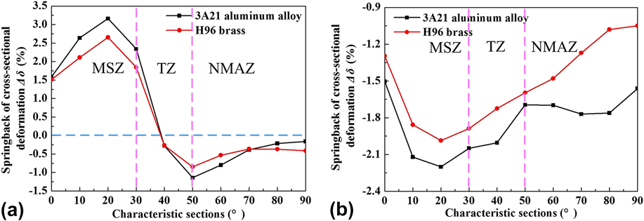
After retracting mandrel, springback of cross-sectional deformation for rectangular tube will take place. Since mandrel-cores just provide a part of support inside the rectangular tube, the effect of retracting mandrel on cross-sectional deformation of different regions is distinguishing. Figure 7(b) shows the distribution laws of cross-sectional deformation for 3A21 and H96 tubes along bending direction after retracting mandrel process. It can be noted that in MSZ, the cross-sectional deformation of 3A21 tube is constantly larger than that of H96 ones. The result above can be explained by the springback amount of cross-sectional deformation Δδ for both tubes after retracting mandrel process. Figure 8 shows the distribution laws of springback amount of cross-sectional deformation for 3A21 and H96 tubes along bending direction after retracting mandrel and springback process. It can be seen from Fig. 8(a), which is obtained by Figs. 7(a) and 7(b), that the springback amounts of cross-sectional deformation for both tubes in MSZ are positive, which means that when mandrel is removed, the cross-sectional deformation of rectangular tube increases, and the springback amounts of cross-sectional deformation for 3A21 tube are constantly larger than that for H96 ones. Springback value is negatively correlated with elastic modulus E and positively correlated with initial yield stress σs, Reference E and Liu18 that is to say, springback value is greater with a larger ratio of initial yield stress to elastic modulus σs/E. Therefore, the main reason is that the ratio of initial yield stress to elastic modulus σs/E for 3A21 tube is larger than that for H96 ones, its ability to resist deformation decreases after unloading, resulting in greater springback amount of deformation.
The distribution of springback amount of cross-sectional deformation for 3A21 and H96 tubes along bending direction: (a) after retracting mandrel process and (b) after springback process.
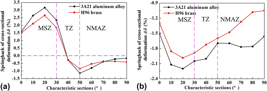
In TZ, the cross-sectional deformation of 3A21 tube is constantly larger than that of H96 ones, but the deformation of both tubes reverses in NMAZ. The changing trend above can also be illustrated by Fig. 8(a). It can be seen that springback amounts of cross-sectional deformation for both tubes have a tendency to change from positive value to negative value. The main reason is that TZ is a transition region from MSZ to NMAZ, springback of cross-sectional deformation here is still influenced by mandrel. The negative values here demonstrate that cross-sectional deformation of rectangular tube decreases in retracting mandrel process because of the internal stress release. In addition, the absolute values of springback of cross-sectional deformation for 3A21 tube are larger than that for H96 ones from sections 40°–70°, which largely attributes to its higher ratio of initial yield stress to elastic modulus σs/E. While from sections 70°–90°, the absolute values of springback of cross-sectional deformation for both tubes reverse. The main reason is that springback is generally a function of the initial stress distribution and the elastic stiffness of material before unloading, Reference Paulsen and Welo5 the initial stress value of H96 tube before retracting mandrel is greater than that of 3A21 ones from sections 70°–90°, as described in Sec. IV.B.2.a, which makes its springback amount of cross-sectional deformation after retracting mandrel larger. Therefore, it can be concluded that from sections 70°–90°, the effect of material property on springback of cross-sectional deformation does not play a major role in retracting mandrel process. The positions of maximum cross-sectional deformation for 3A21 and H96 tubes are in sections 50° and 80°, indicating that the position of maximum deformation can not be changed by retracting mandrel process.
c. Cross-sectional deformation of 3A21 and H96 tubes after springback process
Figure 7(c) shows the distribution laws of cross-sectional deformation for 3A21 and H96 tubes along bending direction after springback process. It can be found that in MSZ and TZ, the cross-sectional deformation of 3A21 tube is mildly larger than that of H96 ones, while in NMAZ, the deformation of H96 tube is constantly larger than that of 3A21 ones. The phenomena above are also a result of springback of cross-sectional deformation Δδ for both tubes after springback process. Figure 8(b) shows the distribution laws of springback amount of cross-sectional deformation for 3A21 and H96 tubes along bending direction after springback process, which is obtained by Figs. 7(a) and 7(c). The negative values here represent the decrease in cross-sectional deformation after springback process. It can be found from Fig. 8(b) that the absolute values of springback of cross-sectional deformation for 3A21 tube are continuously larger than that for H96 ones. The main reason is that the ratio of initial yield stress to elastic modulus σs/E for 3A21 tube is higher than that for H96 ones, making its springback amount of cross-sectional deformation greater. The positions of maximum cross-sectional deformation for 3A21 and H96 tubes are still in sections 50° and 80°, respectively, which reveals that the springback process can not change the position of maximum deformation.
V. CONCLUSIONS
-
(1) Based on ABAQUS Explicit/Standard platform, 3D FE models of bending, retracting mandrel and springback of 3A21 and H96 rectangular waveguide tubes have been built, respectively, and the reliability of the models were verified experimentally.
-
(2) When no mandrel is used, the position of initiating wrinkle for H96 tube is more near to the final bending section compared with that for 3A21 tube, and the position of wrinkle initiation is much related to the initial yield stress. Furthermore, the cross-sectional deformation of H96 tube along bending direction is more homogeneous in contrast to that of 3A21 tube, which is mainly attributed to its higher hardening exponent.
-
(3) When a mandrel is used, the cross-sectional deformation of 3A21 tube after bending is in coincidence with that of H96 tube in MSZ, and the deformation of 3A21 tube is larger in TZ while smaller in NMAZ compared with that of H96 tube. After retracting mandrel or springback, the cross-sectional deformation of 3A21 tube in MSZ and TZ is constantly larger than that of H96 tube, while in NMAZ, the deformation of both tubes reverses.
-
(4) The positions of maximum cross-sectional deformation for 3A21 and H96 tubes after bending are separately located in sections 50° and 80° and can not be changed by retracting mandrel or springback process.
ACKNOWLEDGMENTS
The authors would like to thank the National Natural Science Foundation of China (No. 51375392) and the Research Fund of the State Key Laboratory of Solidification Processing (NWPU), China (No. 152-ZH-2016) for the support given to this research.