I. INTRODUCTION
Carbon nanotubes (CNTs) and polymer nanocomposites have attracted much attention in the last couple of decades. Reference Iijima1–Reference Spitalsky, Tasis, Papagelis and Galiotis3 Convenient processing of polymers in microtechnology environments, combined with exceptional properties of CNTs, Reference Zhang and Iijima4 is expected to produce a variety of structural Reference Qian, Greenhalgh, Shaffer and Bismarck5 and functional Reference Ahir and Terentjev6,Reference Bar-Cohen7 applications. Despite a promising application space, effective processing and manufacturing remain elusive. Understanding of dynamics at the CNT–polymer interface as well as development of fine control over atomistic detail at such interface sit at the core of this promising material system. In particular, it is well established that the synthesis of mechanically efficient polymer–CNT composites requires dispersion and alignment of CNTs in the hosting matrix. Reference Xie, Mai and Zhou8 Recently, the dispersion of nanofillers has been reported through polymer wrapping in the absence of either covalent or noncovalent functionalization of CNTs Reference Baskaran, Mays and Bratcher9 through stirring methods at room temperature, attributed to CH–π interactions.
Electrospinning, Reference MacDiarmid, Jones, Norris, Gao, Johnson, Pinto, Hone, Han, Ko, Okuzaki and Llaguno10 through the combination of extrusion and electrodynamical processes, has been identified as a powerful method toward simultaneous alignment and dispersion of CNTs. Reference Yeo and Friend11 In this scenario, the as-grown surficial structure of CNTs is thought to remain intact upon processing, and we have recently reported on the suitability of electrospinning to promote noncovalent interactions at the untreated multiwalled CNT (MWCNT)/polymer interface through CH–π and H bonding. Reference Winter, Alamgir, Jaye, Fischer and Campo12 The importance of the interface layer is by now well established, Reference Schadler, Giannaris and Ajayan13 and it is through this interface that the composite properties are modified.
Characterization of nanocomposites by electron microscopy has been attempted since last decade, facing poor electron contrast, charging, and local heating. Reference Yeo and Friend11,Reference Kovacs, Andresen, Pauls, Garcia, Schossig, Schulte and Bauhofer14 Selection of sample preparation (i.e., deposition of a conductive coating layer), imaging modes, and irradiation conditions are particularly challenging in the study of polymer nanocomposites due to a small dimension of fillers and also to mechanical and conductive differences between filler and matrix. Recent remarkable developments in low atomic number-ion microscopy have resulted in the availability of helium ion microscopy (He-IM). He-IM features extremely high resolution and surface sensitivity, Reference Ananth, Scipioni and Notte15 owing to a small surface interaction volume. Reference Bell, Lemme, Stern, Williams and Marcus16
Despite its recent inception, He-IM is being deployed toward the imaging of highly diverse soft matter systems, such as cancer cells, Reference Bazou, Behan, Reid, Boland and Zhang17 providing subnanometer resolution over virtually untreated- and undamaged-irradiated surfaces. Similar to the more established Ga-ion beam platform (FIB), He-IM affords manufacturing capabilities, Reference Rudneva, van Veldhoven, Malladi, Maas and Zandbergen18 having lithographically etched 15 nm line-widths on graphene. Reference Bell, Lemme, Stern, Williams and Marcus16
In this paper, we present the first study of electrospun CNT–polymer composites by He-IM. Reference Ananth, Scipioni and Notte15,Reference Joy19 Despite a developing body of the literature to fully elucidate contrast mechanisms in He-IM, Reference Joy19–Reference Ramachandra, Griffin and Joy21 adequate image interpretation remains challenging, as well as a thorough understanding of the possibilities that this new imaging tool presents. Here, we offer an account for the observed surficial topography of electrospun PDMS–PMMA–CNT fibers. Further, we propose that the advent of He-IM imposes an inflection point toward understanding of the extremely dynamical character of electrospinning. Incidentally, a full discussion is invested into explaining previously unreported ripple formation around the CNTs in an effort to contribute to the understanding of contrast mechanisms in He-IM of polymer nanocomposites, where the matrix is actually a blend of two polymers. A thorough discussion of He ion beam–matter interaction confirms that the contrast is not artifact. Our findings suggest that He-IM, in the absence of surface treatments prior to irradiation, unveils previously unreported conformational arrangements between CNTs and hosting polymer blend, pointing at complex dynamical processes upon fiber collection during electrospinning. Contributed information from secondary electron microscopy (SEM), transmission electron microscopy (TEM), and interfacial energies suggests that the phase segregated PMMA preferentially hosts the CNTs, whose native morphology cannot explain rippling. Since prior near edge x-ray absorption fine structure (NEXAFS) had predicted a model where PMMA chains would preferentially show conformational effects upon CNT wrapping, Reference Winter, Alamgir, Jaye, Fischer and Campo12 we propose that rippling results from nanofiller drag upon collection. These results further highlight the value of He-IM in the study of soft matter and nanocomposites.
II. EXPERIMENTAL
Poly(methyl methacrylate)–polydimethylsiloxane (PDMS–PMMA) was blended at a 1:1 ratio on dimethylformamide (DMF) and tetrahydrofuran (THF), following the procedure described by Yang et al. Reference Yang, Liu, Jin, Zhu, Zeng, Jiang and Ma22 PMMA was purchased from Sigma Aldrich with a density of 1.2 g cm−3 and an average molecular weight of 996,000. PDMS Sylgard 184 silicone elastomer was purchased from Dow Corning, with a density of 1.0 g cm−3 and a molecular weight of ∼60,000. DMF and THF were both purchased from Sigma Aldrich. Two types of MWCNTs were purchased from Nanostructured & Amorphous Materials, Inc. namely smaller (30–50 nm diameter, 0.5–2 μm length) and larger (50–80 nm diameter, 5–15 μm length) fillers.
A solution prepared from 2.04 g of PMMA, 10 mL of DMF, and 10 mL of THF was mixed at 50 °C for 1 h under constant magnetic stirring. Upon cooling, 2.02 mL of Sylgard 184 and 0.2 mL of PDMS curing agent were added to the mixture. Finally, two types of unmodified MWCNTs were added to produce two composite samples. Polymer blends (1:1 ratio) produced composites containing small (0.6 wt%) and large (0.2 wt%) MWCNTs, which were kept under magnetic stirring at room temperature. Electrospinning (aided by a syringe pump and a power supply) was conducted at room temperature (10 kV, 5 cm emitter/collector distance) onto a rotating drum under a white lamp to assist residual solvent evaporation. As a result, fibers assembled to produce dry mats, which were easily peeled from the collector, avoiding stiction.
The untreated fibers were imaged in an ORION Plus He-IM Zeiss at 35 kV with the assistance of a flood gun to prevent surface charging. With the purpose of establishing a baseline of comparison with conventional SE imaging, SEM images were acquired at 5 keV on a FEI-235 Strata in a SE mode, where the mats were Au-coated to prevent electron charge build up. Focus ion beam milling facilitated cross-section inspection. TEM images were acquired in a JEOL JEM-2010F field emission operated at 200 kV and a JEOL JEMARM 200F electron microscope. STEM images were simultaneously recorded in both the high-angle annular dark-field (HAADF) and bright-field (BF) modes at 80 kV. Probe correction was performed with a CEOS corrector obtaining a 12-fold Ronchigram with a flat area of ∼40 mrad. Images were registered with a condenser lens aperture of 30 μm (convergence angle 25 mrad), and HAADF collection angles ranged from 45 to 180 mrad. The spot size used was ∼35 pA.
III. RESULTS AND DISCUSSION
A. Imaging
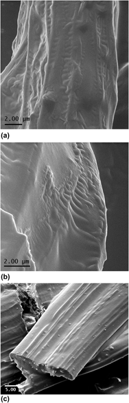
He-IM images in Figs. 1(a) and 1(b) show fibers hosting large and small CNTs, respectively. In this scenario, surficial CNTs appear parallel to the spun fibers, revealing dispersion and alignment behavior that will be confirmed by SEM in Fig. 1(c). Surprisingly, the rippling effects are observed perpendicularly to the CNT axis in both composites. The lengths of these undulations vary from a few hundred nanometers across larger CNTs to over a micrometer in smaller CNTs and bear hints of periodicity. Through line scan profiles, we have examined the periodicity of the rippled structures along large and small CNTs in Fig. 1, providing an average of 300 and 700 nm, respectively.
Electrospun fibers hosting large CNTs viewed by He-IM imaging in the absence of coating (a). He-IM image of uncoated composite fibers hosting small CNTs (b). SEM image (c) reveals rich contrast of the embedded CNTs in the matrix, protruding through the cross-section.

With the purpose of establishing a baseline of comparison with conventional SE imaging, SEM was conducted on Au-coated composites (containing the CNTs with the larger diameter) on a DB-FEI FIB system. The SEM image in Fig. 1(c) reveals rich contrast of the embedded CNTs in the matrix, protruding through the cross-section. The individual CNTs as seen in the cross-section confirm the ability of untreated CNTs to be dispersed through a combination of polymer wrapping, Reference Baskaran, Mays and Bratcher9 and the shear action during extrusion in electrospinning, in the absence of additional dispersants or CNT modification. Indeed, there is evidence of CH–π interactions in our PDMS–PMMA composites between filler and matrix, despite the absence of CNT postsynthesis processing. Reference Winter, Alamgir, Jaye, Fischer and Campo12 Fiber surfaces appear with some level of roughness, but mostly dominated by the undulation provided by CNTs embedded closely to the top surface. A combination of topographic and electrical conductive differences between filler and matrix is likely to be responsible for the increased secondary electron signal originating from the resulting aligned and dispersed CNTs.
The topographic contrast from He-IM, however, differs greatly. Unsurprisingly, the enhanced surficial sensitivity in He-IM, combined with an absence of charging artifacts, seems to uncover the genuine topography of uncoated fibers. Similar to those findings in the study of cancer cells, Reference Bazou, Behan, Reid, Boland and Zhang17 a whole new level of detail is present.
In view of these results, two questions need addressing. First, the reasons why additional contrast is observed in He-IM and not in SEM imaging, need a thorough examination. The second question aims at elucidating the ultimate physical origin of the observed features. In this section, the first question will be addressed. Sections III. B and C will discuss NEXAFS, SE, and TEM findings to propose a physical model to rippling features in Fig. 1. The stability of nanocomposites under He beam irradiation is addressed in Sec. III. D; and finally, the drag from interfacial polymeric layers will be proposed to the observed rippling and flow morphologies in Sec. III. E.
He-IM features extremely high surface sensitivity and resolution,
Reference Ananth, Scipioni and Notte15
the former owing to a small surface interaction volume.
Reference Bell, Lemme, Stern, Williams and Marcus16
Three factors contribute to an increased resolution in He-IM: smaller iSE diffusion lengths, reduced iSE2/iSE1 ratios, and the absence of electrostatic charging.
Reference Joy19
Joy and coworkers have modeled SE imaging in He-IM,
Reference Ramachandra, Griffin and Joy21
emphasizing the role of particle velocity (rather than energy) in ion beam–sample interaction, following J.J. Thomson's formulation. In this scheme, the He ion velocities in the solid are two orders of magnitude smaller than electrons. As a consequence, stopping power profiles peak at higher He ion beam energies, and the penetration depth of He ions is sensibly reduced compared to that of electrons. Full electron (R
e−) and 90% ion range (R
90% He+) have been calculated for PDMS and PMMA targets through the Kanaya–Okayama equation
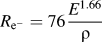 ${R_{{{\rm{e}}^ - }}} = 76{{{E^{1.66}}} \over \rho }$
and the IONISE predictions
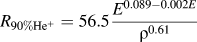 ${R_{90\% {\rm{H}}{{\rm{e}}^ + }}} = 56.5{{{E^{0.089 - 0.002E}}} \over {{\rho ^{0.61}}}}$
Reference Ramachandra, Griffin and Joy21
; where E and ρ refer to incident beam energy and target density, respectively.
Reference Ramachandra, Griffin and Joy21
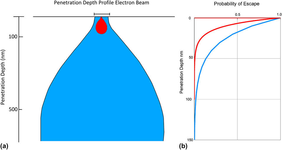
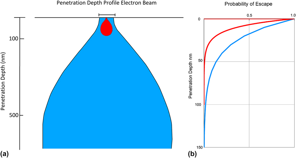
Calculations yielded approximately 1000 nm penetration depth for electrons and 60 nm for He ions in both materials systems (Fig. 2). Given the similar densities of PMMA and PDMS, and the moderate ion beam energy (E < 50 keV), neither the relative ratio in the polymer blend, nor the well-known phase segregation between both systems would have an impact on the estimated ranges plotted in Fig. 2.
Penetration depth profile of electron and He ion beams (a), and escape probability of secondary electrons (b). Blue and red graphs refer to electron and He, respectively.
Not only is the energy of the incident ion beam deposited in a reduced volume but also the fraction volume actively contributing to emitted SE is smaller as well, by virtue of reduced effective diffusion lengths.
Reference Ramachandra, Griffin and Joy21
Since the probability p(z) of secondary electrons subject to been collected by imaging detectors can be modeled as escaping from a surface by way of diffusion,
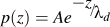 $p\left( z \right) = Ae^{{\raise0.7ex\hbox{${ - z}$} \!\mathord{\left/ {\vphantom {{ - z} {\lambda _d }}}\right.\kern-\nulldelimiterspace}\!\lower0.7ex\hbox{${\lambda _d }$}}}$
follows, where A is an scaling constant and z is the depth. The tabulated values of the effective diffusion length of secondary electrons for He and ion beam irradiation, λd, exist for a number of elements.
Reference Ramachandra, Griffin and Joy21
By assuming a C target, λd has been found to be 10 and 25 Å for He ion and electron beam irradiation, respectively, and p(z) is plotted in Fig. 2(b). Our estimations indicate that for an ideal C target, 70% iSE versus 40% eSE are emerging from the surface within the first 10 nm of the surface, conferring He-IM a higher sensitivity to surficial features and justifying the presence of additional topography, compared to SE imaging.
The decreased penetration depth of the He ion beam as well as enhanced SE escape profile has important consequences in charge management, a major roadblock on the characterization of polymer nanocomposites by electron microscopy (Ref. Reference Kovacs, Andresen, Pauls, Garcia, Schossig, Schulte and Bauhofer14 and references therein). In particular, the He beam primarily produces a surface charge distribution, with relatively little subsurface charging, as can be seen in Fig. 2. For insulators, the residual surface charge can be easily balanced with a low energy electron flood gun. The electron beam deposits charge deep below the surface, where it is not readily dissipated or neutralized. Conventional coating layers deposited on soft materials introduce artifacts conducive to misinterpretation, Reference Bazou, Behan, Reid, Boland and Zhang17,Reference Joens, Huynh, Kasuboski, Ferranti, Sigal, Zeitvogel, Obst, Burkhardt, Curran, Chalasani, Stern, Goetze and Fitzpatrick23 and the need for highly conformational is clearly highlighted by He-IM.
Another crucial aspect to explain He-IM contrast is resolution. Indeed, SE can be emitted from both the point of impact on the electron beam (SE1) as well as from the adjacent region, within the interaction volume (SE2). In fact, SE2 can originate with some probability within the region above the interaction volume, clearly degrading resolution. The semiempirical calculation proposed by Ramachandra et al. Reference Ramachandra, Griffin and Joy21 indicates that the ratio of eSE2/eSE1 is of the order of 1:1, independent of the target, for electron beam energies of about 20 keV. However, the He-ion beam generated SE at 40 keV for Al in a distribution of iSE2/iSE1 ∼ 0.1 for Al. Reference Ramachandra, Griffin and Joy21 By this argument, the increased lateral resolution in low atomic number targets can be approximated as (iSE2/iSE1) ∼ 0.1 (eSE2/eSE1).
This discussion highlights the implications of He ion–matter interactions to validate the absence of surficial contrast in SE imaging, albeit observed in He-IM. The justification of the observed He-IM contrast lends to the second research question, on its physical origin. Finally, a word of caution is needed on the interpretation of topographic contrast, as SE imaging correlates with the relative SE yield as an exclusive function of angle of incidence. Remarkably, the topographic yield in He-IM is dependent not only on angle incidence, but also on incident beam energy and sample composition. Reference Ramachandra, Griffin and Joy21 This convoluted dependence is emphasized for medium to high atomic number elements, whose interactions upon He ion beam irradiation could result in mistaken interpretations of sample topography. The species involved in this study are predominantly C; however, the presence of Si in PDMS will need to be addressed to rule out the possibility of enhanced topographic contrast in He-IM (Fig. 1) due, in fact, to a chemical variation by way of localized PDMS surrounding CNTs. This possibility will be the subject of discussion in the next section.
B. NEXAFS contribution to He-IM image interpretation
Given the convoluted influence of topography and atomic number on SE yield-in He-IM, as well as the disparity in contrast interpretation as compared with SEM, additional information on the PDMS–PMMA/CNT composite is needed to explain the rippling effect in Fig. 1. In particular, if scattering species with higher atomic number generate increased SE emissions, could the rippling effect be in fact produced by chemical-contrast by Si-on PDMS, which could be preferentially adsorbed to the nanofillers? This question will be addressed by synchrotron-spectroscopic techniques as well as through thermodynamic predictions to address the selective localization of CNTs in segregated blends.
Although chemical information often proves an useful addition to all modalities of electron microscopy, the impossibility of x-ray microanalysis in He-IM has been demonstrated, Reference Joy19 and alternative chemistry-resolving techniques are being currently explored as a complement to He-IM, such as secondary ion mass spectroscopy (SIMS). The convenience of spectroscopy techniques that can provide both element identification as well as chemical state of such elements is clearly advantageous in polymeric systems, and further enhanced in CNT nanocomposites, in the presence of a dominant C. NEXAFS spectroscopy sits amongst such highly informative chemical spectroscopic techniques. Reference Stöhr24 Despite being an ex situ approach (given the requirement of impinging synchrotron radiation), its nondestructive character might offer an alternative to SIMS. In NEXAFS, photoabsorption of monochromatic x-rays whose energy is scanned around an absorption edge leads to the generation of photoelectrons and core holes, to be filled by Auger decay. The emitted primary Auger generates additional secondary electrons through the effective sampling depth, L, which is typically a few nanometers, whereas the Auger is on the order of 1 nm or less. Reference Stöhr24 Further, a detailed analysis to determine the electron escape depths for NEXAFS spectroscopy found a strong dependence on carbon atom density, in the case of polymeric systems. Reference Sohn, Dimitriou, Genzer, Fischer, Hawker and Kramer25 In addition, surface sensitivity can be tailored by modifying retarding voltages on the acquiring detectors.
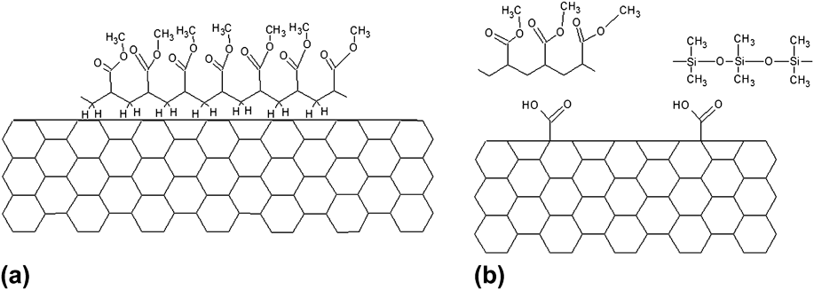
With all, since typical sampling depths associated with NEXAFS are within the range of 1–10 nm, Reference Stöhr24 findings on the molecular fingerprints from this nanocomposite blend can legitimately contribute to the observed He-IM contrast. Our group has recently reported NEXAFS studies of electrospun PDMS–PMMA/CNT composites. Indeed, there is evidence of CH–π interactions in our PDMS–PMMA composites between filler and matrix, despite the absence of CNT postsynthesis processing, Reference Winter, Alamgir, Jaye, Fischer and Campo12 and a conformational model has been proposed, where PDMS and PMMA interact with CNTs through H bonds (Fig. 3). Interestingly, the extent of noncovalent interaction was higher for large CNTs, suggesting stronger matrix conformation, to produce improved wetting of CNT surfaces by means of a tightly bound polymer layer by way of nanomechanical interlocking. Although a thorough discussion on mechanical properties of nanocomposites is out of the scope of this work, a brief mention is made due to their relevance. The effects of nanoparticle addition to polymeric matrices have been recently documented in both thin film and electrospun modalities, Reference Panzavolta, Bracci, Gualandi, Focarete, Treossi, Kouroupis-Agalou, Rubini, Bosia, Brely, Pugno, Palermo and Bigi26 highlighting the role of system geometry. Indeed, a rigorous correlation between interfacial strength and overall composite performance hinders on the mechanics versus geometry argument. Reference Carpinteri and Pugno27 In the composites discussed here, this complexity is further augmented both as a result of blend electrospinning and the use of nanoparticles with different sizes. Clearly, more research is needed in this realm, following innovative trends which combine molecular dynamics and hierarchical arguments. Reference Giesa, Pugno, Wong, Kaplan and Buehler28
Proposed CH–π (a) and H-bonding models (b) on PDMS/PMMA/CNT composites, where NEXAFS analysis has confirmed PMMA as the main phase bonding to CNTs. Reference Winter, Alamgir, Jaye, Fischer and Campo12

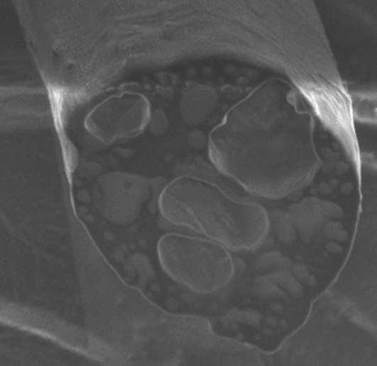
Further, the cross-sectional imaging of electrospun (ES) composites (Fig. 4) shows the dominant character of PMMA in the blend, where PDMS droplets phase-segregate. Indeed, Si-rich PDMS regions appear brighter on the SEM image by virtue of backscattering electron contrast. It is worth clarifying that in SE imaging, backscattered electrons (whose generation is a function of the atomic number of the target) emitted within the solid angle of the detector are collected and registered within an otherwise SE-dominant contrast. In Fig. 4, higher atomic number of Si in PDMS enhances backscattered electron generation, as seen in the bright regions. As described in detail earlier, Reference Winter, Alamgir, Jaye, Fischer and Campo12 PMMA (dark contrast in Fig. 4) is the dominant component in the system, where PDMS preferentially segregates.
Cross-sectional SE image of a freshly FIB polished fiber, showing PMMA (dark) and PDMS (bright) phase separation. Fiber diameter is 10 μm.

The selective localization of CNTs in segregating blends has been studied thoroughly toward the optimization of, for example, conductive properties in highly relevant segregating blends in industrial applications. Reference Göldel, Kasaliwal and Pötschke29 Indeed, following the arguments by Potschke and coworkers, interfacial energy considerations in the MWCNT|PDMS–PMMA system can be described by the wetting coefficient w a as:
 $${w_{\rm{a}}} = {{{\gamma _{{\rm{CNT}} - {\rm{PDMS}}}} - {\gamma _{{\rm{CNT}} - {\rm{PMMA}}}}} \over {{\gamma _{{\rm{PDMS}} - {\rm{PMMA}}}}}}\quad {\rm{.}}$$
By this definition, CNTs are predicted to be localized within PDMS phase if w a < −1, and within PMMA phase if w a > 1. For −1 < w a < 1, CNTs predicted to be at interphase. Interfacial energies can be calculated by either the harmonic [1] or the geometric [2] mean equations:
 $${\gamma _{12}} = {\gamma _1} + {\gamma _2} - 4\left[ {{{\gamma _1^d\gamma _2^d} \over {\gamma _1^d + \gamma _2^d}} + {{\gamma _1^p\gamma _2^p} \over {\gamma _1^p + \gamma _2^p}}} \right]\quad {\rm{,}}$$
 $${\gamma _{12}} = {\gamma _1} + {\gamma _2} - 2\left[ {\sqrt {\gamma _1^d\gamma _2^d} + \sqrt {\gamma _1^p\gamma _2^p} } \right]\quad {\rm{,}}$$
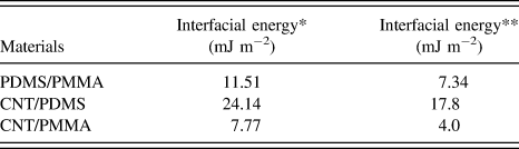
where γ1 and γ2 are surface energies of components 1 and 2, γ1 d and γ2 d are disperse parts of surface energies of components 1 and 2, and γ1 p and γ2 p are polar parts of surface energies of components 1 and 2. These data have been compiled from the literature, with γPDMS = 20.4 mJ m−2 (γPDMS d = 19.5 and γPDMS p = 0.9) Reference Brandrup, Immergut, Grulke, Abe and Bloch30 , γPMMA = 41.1 mJ m−2 (γPMMA d = 29.0 and γPMMA p = 12.1), Reference Wu31 and γCNT = 45.3 mJ m−2 (γCNT d = 18.6 and γCNT p = 26.7). Reference Nuriel, Liu, Barber and Wagner32 The calculated interfacial energies following Eqs. (1) and (2) in Table I provide wetting coefficients w a of 1.42 and 1.88, respectively, whereby MWCNTs are predicted to preferentially migrate to PMMA phase-segregated regions.
C. Structural study of MWCNTs
This discussion has effectively ruled out the possibility of Si-enhanced contrast in Figs. 1(a) and 1(b). Both NEXAFS and thermodynamic arguments indicate that the polymer phase tightly surrounding large and small MWCNTs is PMMA, and that the enclosing matrix is also PMMA. Chemical effects that He-IM can potentially register have been ruled out by virtue of thermodynamics of the origin of morphologies seen in Fig. 1, which is still under discussion. They could result from structural conditions or processing mechanisms. CNTs have been studied thoroughly through high-resolution electron microscopies, and the presence of periodic defects along graphitic walls on the as-grown tubes has not been identified to date, Reference Tanaka, Yamasaki, Kawai and Pan33 suggesting that the origin of periodic undulations is likely to result from processing. Still, the question arises whether CNTs used in this particular study could induce rippling by molding pre-existing periodic defects into the matrix. Indeed, STEM imaging of the large CNTs used in this study shows the habitual graphitic layering (Fig. 5), with some of the external walls indicating some sign of damage [Fig. 5(a)]. The undulations seen at lower magnification in dark field imaging [Fig. 5(b)] present the radii of curvatures in the order of nanometers, rather than micrometers, and they appear randomly along CNTs. Additional rippling is observed locally within the graphitic walls and these defect systems are very localized to a few nanometers along the CNTs, showing defective atomic displacements in the order of angstroms [Fig. 2(d)]. These results rule out the role of native CNT defects in ripple formation. It is worth highlighting that the periodicity suggested in Figs. 1(a) and 1(b) is not spatially uniform. Figure 6 shows the He-IM image of a composite hosting small MWCNTs, acquired at different locations compared to Fig. 1(b). The line scan profile along the MWCNT [Fig. 6(b)] shows rippling with a periodic average of 60 nm. The extent of the ripples can extend beyond 200 nm, perpendicularly to the length of the MWCNT wetting Reference Göldel, Kasaliwal and Pötschke29 and NEXAFS spectra, suggesting that the ripples in Figs. 1(a) and 1(b) are, in fact, of topographic nature.
Aberration-corrected STEM bright (a, c, and d) and dark field (b) images showing random structural defects, with curvature radii orders of magnitude smaller than the rippling effect in electrospun fibers.

Surficial CNT (small) on an electrospun fiber showing rippling effects perpendicularly to the CNT length. Small composite (a) and line scan profile suggesting a ripple periodicity of 60 nm (b).

At this point in the discussion, chemical and structural scenarios to generate rippling effects have been ruled out. The presence, however, of a tightly wrapped PMMA coating layer around MWCNTs has been confirmed by thermodynamical prediction and NEXAFS spectroscopy, and its role during electrospinning remains undiscussed. In fact, the origin of driving forces conducive to nanofiller drag upon emission from the spinneret could be related to kinematic effects upon collection. Upon emission, the electrospun fiber is ejected at a certain kinetic energy E 1, owing to a combination of extrusion and electrostatic potential difference between the emitter and the collector. Upon deposition on the grounded collector, the kinetic energy of fibers is decreased (E 2), matching that of the rotating drum (E 2 < E 1). Embedded nanofillers will invest their excess energy through flow in a matrix where solvent has not been fully evaporated, and therefore amenable to nanoparticle drag. The feasibility of such highly dynamical processes is unsurprising, given spinodal decomposition already affords substantial mass transfer, as it is often seen during pore formation. The tribology properties of PDMS and PMMA have been thoroughly studied in the context of microfabrication technologies, where accelerometer comparative performance identifies PMMA as the material with higher friction during high velocity behavior due to localized melting from asperity impacts. Reference Tambe and Bhushan34 The rippling effect is the plastic response of “bulk” PMMA to the “tightly bound” PMMA–CNT ensemble. The observed undulations offer an insight into early stages of fiber deposition upon the collector, highlighting viscoelastic phenomena and non-Newtonian fluid behavior, Reference Yeo and Friend11 at a stage where solvents have not fully evaporated.
D. Stability of polymer nanocomposites under He beam irradiation
Cross-section geometry, surface morphology, and inner porosity in ES fibers are all active topics of research, Reference Pai, Boyce and Rutledge35 as different morphologies have been correlated with mechanical performance. He-IM, unlike SEM, allows for prolonged irradiation exposure needed for thorough morphological analysis, without detriment to the target, given the reduced He-ion beam damage (i.e., charging, heating), even in soft matter systems. Further inspection of the electrospun fibers revealed well-known porosity [Fig. 7(a)]. Surficial porosity on fibers has been attributed to thermodynamic instabilities on the jet upon ejection due to a rapid evaporation of solvent, resulting in quenching and spinodal decomposition (as mentioned in the previous section) into polymer- and solvent-rich phases that in turn yield matrix solidification and pore formation, respectively. Reference Kim, Michler and Pötschke36 Some areas on the imaged fibers show complex contrast owing to convex oriented CNTs [Fig. 7(b)] seemingly flowing through the matrix. This contrast differs greatly from prior reports demonstrating nucleation of nanocrystalline domains. Reference Liu, Chen, Zussman, Korach, Zhao and Rafailovich37 In fact, cross-sectional analysis of these fibers had demonstrated that the outer layer of these fibers is mostly dominated by PMMA, Reference Winter, Alamgir, Jaye, Fischer and Campo12 with well-known amorphous structure. The image in Fig. 7(b) captured fillers' drag in the matrix by local mass transfer mechanisms, creating a variety of dips and protrusions that, through dissipative friction, eventually engulf fillers.
Overview of complex topography on electrospun composites: (a) Surficial pores caused by solvent evaporation, (b) CNT (large) drag upon fiber collection, and different degrees of polymer coating and CNT alignment for large (c) and small (d) CNTs.

Interestingly, MWCNTs in Figs. 1(b) and 1(c) seem to flow, and they drag as shown in Fig. 1(c). In addition, MWCNTs in Figs. 1(b) and 1(c) seem “shorter” than those in Fig. 1(c). It is unclear whether the CNTs have gone through scission during processing, or perhaps they have just not been well aligned locally, and hence, only emerging partially to the surface. In either case, if electrospinning, through electro-hydrodynamic effects, is helping to nucleate a tightly bound PMMA layer to the MWCNTs, both shorter and misaligned CNTs will experience this shear-flow less efficiently, and hence, the formation of the wetting layer would be inhibited.
Flory–Huggins theory has been applied to study mass transfer. A variety of wrinkled morphologies have been reported in ES polystyrene, Reference Pai, Boyce and Rutledge35 whose recurrence, as the theory predicted, strongly depended on background humidity, affecting drying, buckling, and phase separation times. This phenomenology could be enhancing contrast seen axially in aligned CNTs, as seen in Fig. 7(b), although it would not explain the deep ridges seen perpendicularly to the fillers in Fig. 1.
E. Drag from interfacial polymeric layers as a proposal to the observed rippling and flow morphologies
As mentioned earlier, it is crucial to develop an understanding of CNT–polymer interfaces to tailor overall mechanical properties in composites. In particular, the presence of an interfacial polymeric layer tightly bound to CNTs has been identified, Reference Yu, Tonpheng, Gröbner and Andersson38 and its thickness engineered through enhanced cross-linking density.
Results showed increased load transfer and mechanical reinforcement through thicker interfacial layers, further justifying the importance to identify synthetic procedures conducive to improved mechanical load transfer through these primary coating layers. Figures 7(c) and 7(d) [as well as Figs. 1(a) and 1(b)] suggest that interfacial layers around large CNTs could be thicker, as well as more strongly bound. Support for this argument is provided by NEXAFS. Indeed, we have observed that large CNTs appear to have stronger CH–π interactions, with more pronounced conformational effects. Reference Winter, Alamgir, Jaye, Fischer and Campo12 Different degrees of conformational wrapping could be the result of smaller and shorter CNTs unable to experience enough shear flow, Reference Kim, Michler and Pötschke36 yielding reduced nanomechanical interlocking, Reference Wong, Paramsothy, Xu, Ren, Li and Liao39 which would result in reduced CH–π interactions, inhibiting effective polymer coating. It is worth highlighting that the presence of a tightly bound-polymer coating around the CNT by CH–π interactions is well established. Reference Beigbeder, Linares, Devalckenaere, Degée, Claes, Beljonne, Lazzaroni and Dubois40 Figure 8 shows two scenarios where a single CNT is tightly coated by such an interfacial polymeric layer. In fact, both snapshots in Fig. 8 reveal scenarios where CNTs are supporting a load [Fig. 8(a)] or have fractured as a result of strain [as seen in Fig. 8(b) and inset]. Further, the deformed pattern of the CNT in Fig. 8(b) correlates with some predicted deformations from CNTs under load. Reference Zhang, Wang and Tan41 Incidentally, it is worth noting that images in Fig. 8 reveal extreme stability of CNTs under the helium beam, the absence of oscillatory behaviors typically observed in nanowires by electron microscopy, Reference Nam, Jaroenapibal, Tham, Luzzi, Evoy and Fischer42 showing the promise of He-IM as an in situ platform. Indeed, recent publications point at the importance of fracture dynamics in electrospun polymer nanocomposites, Reference Panzavolta, Bracci, Gualandi, Focarete, Treossi, Kouroupis-Agalou, Rubini, Bosia, Brely, Pugno, Palermo and Bigi26 where fracture processes are modeled rather than visualized.
Single large CNT under tension from two adjacent fibers (a) single small CNT emerging from the bulk of strained fiber (inset); (b) Single CNT under tension between fiber and substrate.

Interfacial energies calculated through harmonic (*) and geometric (**) mean equations.

IV. CONCLUSIONS
Electrospun nanocomposites have been studied by He-IM, offering a qualitative overview of CNT arrangement and its interaction with the hosting matrix. Results suggest that the as-spun fibers could remain a highly dynamic system prior to full solvent evaporation and cross-linking, owing to nanofiller residual momentum from projectile and shear flow. This study suggests the origin of driving forces conducive to nanofiller drag upon emission from the spinneret is related to kinematic effects upon collection. Upon CNT shear flow on the rotating collector and nucleation of a tightly bound PMMA layer, bulk PMMA responds with surficial dynamic rippling. This elastic deformation becomes plastic upon momentum extinction and matrix solidification. Simplicity on electrospinning set up highly contrasts the complexity involved during processing. Multiple instabilities (inclusive of evaporation and spinodal decomposition) with profound effects on morphologies and shear flow of CNTs upon collection are possibly influencing surface fiber topography during pore dynamics and “smearing”. He-IM has offered an insight into early dynamics upon electrospinning: from collection to evaporation, further highlighting the importance of these processes. He-IM has also evidenced the presence of a polymeric coating layer around CNTs, highly relevant toward the understanding of crucial properties, such as load transfer or the degree of conformational polymer wrapping. These results strongly propose that He-IM is a promising platform for the in situ studies of mechanical, thermal, and electrical in situ behavior in the realm of soft matter and nanocomposites.
ACKNOWLEDGMENTS
Professor D.C. Joy and Professor J.J. Santiago-Aviles are kindly acknowledged for discussions on He-IM and electrospinning. The authors thank L. Leigh and D. Winter for their help in the assembly of this manuscript. This work was partially funded by grants from the National Center for Research Resources (5 G12RR013646-12) and the National Institute on Minority Health and Health Disparities (G12MD007591) from the National Institutes of Health. The authors would like to acknowledge NSF for support with Grant DMR-1103730, “Alloys at the Nanoscale: The Case of Nanoparticles Second Phase” and NSF PREM Grant # DMR 0934218.