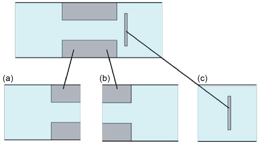
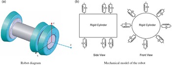
1. Introduction
There was more than 3.5 × 10⁶ km of the oil and gas pipelines worldwide in 2015, increasing by 3.2 × 10⁴ km per year [Reference Karydis1]. By 2020, the length of the oil and gas pipelines will reach 1 × 10⁵ to 1.5 × 10⁵ km in China [Reference Hong, Zhuxin, Yi, Zhang and Yuanyuan2]. Such a huge pipeline network may face the unprecedented problems in the inspection of leak, maintenance, and other aspects. In order to improve the safety and reliability of the oil and gas transportation, these pipelines should be inspected and maintained by a regular basis. The oil and gas transportation in a long-distance pipeline usually not allowed to stop production during the inspection operation, which poses a great challenge. Thus, the long-distance pipeline pig and robots (LDPPRs) are usually used to solve the problems of inspection and maintenance in the long-distance oil and gas pipeline. In addition, the LDPPRs can make the oil and gas transportation cheaper and safer. With the development of the technology of LDPPRs, the current LDPPRs have operation functions such as intelligent control, speed control, intelligent monitoring, and feedback. They are no longer “pipeline pigs” without control functions and can be called robots.
At present, the LDPPRs are mainly used for the following operations: (1) cleaning the wax and hydrates in the pipeline, (2) inspecting the corrosion and the changes of the pipeline diameter, and (3) pipeline drying. And, the driving energy of a LDPPR for motion or controlling is provided by the kinetic energy of the oil and gas. According to the data published by Pigging Products and Services Association, more than 80 companies worldwide have the ability to use LDPPRs to carry out the above services, and many research teams are also engaged in the research work of the LDPPRs [Reference Karydis1, 3]. However, the safety and reliability of the LDPPRs are still a problem worth studying in the long-distance pipeline.
It is found that the structural characteristics and dynamic mechanical behavior will affect the safety and reliability of the LDPPRs. Therefore, it is important to analyze the structures and mechanics of the LDPPRs. In this paper, according to the structural characteristics, the LDPPRs are classified into the velocity-uncontrollable LDPPR and velocity-controllable LDPPR. The mechanical models of the different structures of LDPPRs and their application conditions are investigated, especially the mechanical models of velocity-controllable LDPPRs. It should be noted that there are three main methods to control the velocity of the LDPPRs, which are friction resistance, driving force, and self-running. Finally, the anti-stuck technologies, the inspection technologies, and the location technologies are investigated and analyzed.
2. Structures of LDPPRs
2.1. Structures of velocity-uncontrollable LDPPRs
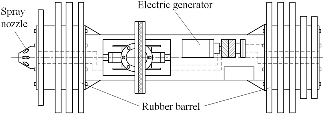
Abney [Reference Abney4] invented a LDPPR with self-generating system, as shown in Fig. 1. The robot uses an electric generator system for power generation, which is used to drive the inspection equipment. When the fluid flows through the robot body, the spray nozzle can produce a fluid jet at the end of the robot. High-velocity fluid can destroy the deposits (wax or rust) on the inner wall of the pipeline, and it can reduce the probability of being stuck.
Self-generating and spraying robot [Reference Abney4].

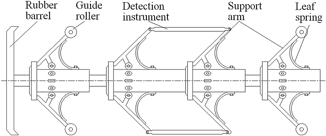
Comello et al. [Reference Comello, Laursen and Maki5–Reference Comello, Laursen and Maki7] developed a diameter-adaptive LDPPR, as shown in Fig. 2. The guide roller and detection instrument of the robot are connected to the support arm, and the support arm can expand in radial direction by the spring force. Then, the robot can make the detection instrument or guide roller contact the wall of the pipe. At the same time, it will reduce the radial force acting on the rubber barrels to improve the service life of the rubber barrel. In addition, once it starts to work, the velocity of the robot cannot be directly controlled.
Diameter-adaption pipeline robot [Reference Comello, Laursen and Maki5–Reference Comello, Laursen and Maki7].

The fluid rheology and the pipe geometry are the main factors which can influence the velocity of the LDPPRs. It needs to be emphasized that the robots (Figs. 1 and 2) do not have the function of the velocity control. However, the robot velocity will affect the accuracy of the inspection data and the reliability of other operations. So, the velocity-controllable LDPPR is the focus of the research.
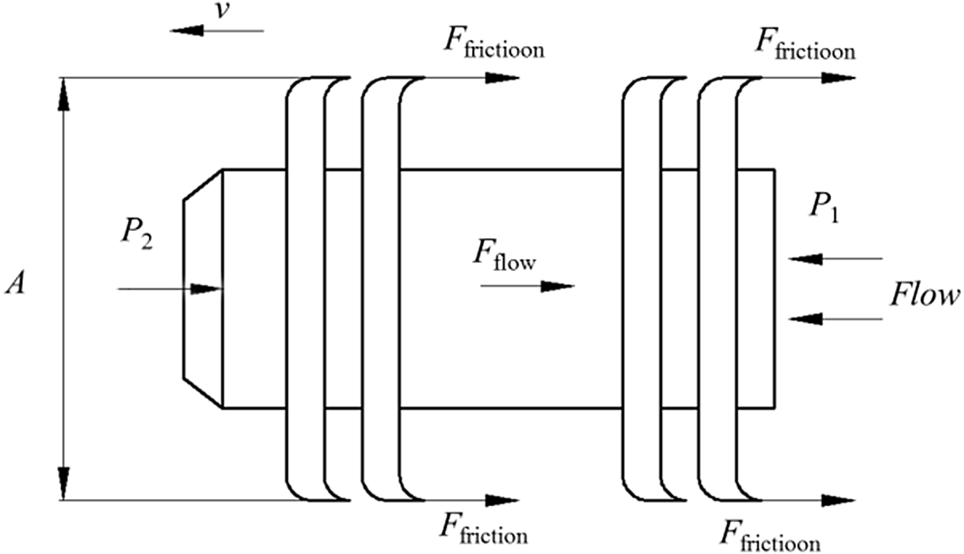
Figure 3 shows the mechanical model of the LDPPRs. In this figure, F friction is the friction resistance between the pipe wall and the LDPPR; P1 and P2 are the pressure of the oil and gas; A is the cross-sectional area of the LDPPR, and a is the acceleration.
Dynamic model of a LDPPR.

From Fig. 3, the flow equation can be achieved:
 \begin{equation} (P_{1}-P_{2})A=F_{\mathrm{friction}}+F_{\mathrm{flow}}+\mathrm{ma} \end{equation}
In Eq. (1), F flow is the fluid resistance force influenced by the velocity, density, and viscosity of the oil and gas. And, it is difficult to control the velocity and the fluid rheology. The driving force which equals to (P 1 – P 2) A can be controlled by a throttling effect. And, F friction can be controlled by the contact force between LDPPR and the wall of a pipe. Therefore, the velocity of the LDPPRs can be controlled by the friction resistance and the driving force. Besides, the robot also can run by itself. So the LDPPR can be classified into the friction resistance type, driving force type, and self-running type.
2.2. Structures of velocity-controllable LDPPRs
2.2.1. Velocity controlled by the friction resistance
The LDPPRs can change the contact force between a friction block and the pipe wall in real time according to the velocity feedback. Then the velocity can be controlled within a certain range based on the data of the velocity feedback.
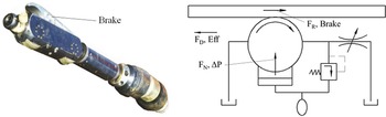
Stoltze [Reference Bjorn and Ewan8–Reference Stoltze10] proposed a LDPPR whose velocity is controlled by a brake system, as shown in Fig. 4. The friction resistance FR between the pipe wall and the brake is controlled by the braking force FN. This process enables the driving force FD and frictional resistance FR to achieve a dynamic balance. Ultimately, this robot can control its velocity in a certain range. The pressure drop is 0.7–2.7 MPa, and the velocity can be controlled at 1/60-1 times of the fluid velocity. The range of the diameter is 6–42 inch (152–1067 mm). The operating temperature is 120 °C and the economic distance is not less than 10 km [Reference Mirshamsi and Rafeeyan41].
Hydraulic brake system used as the mechanism of the velocity control [Reference Bjorn and Ewan8–Reference Stoltze10].

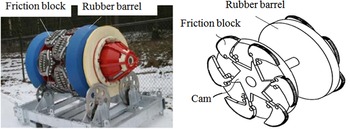
Thomas et al. [Reference Thomas, Stephan and Hubert11–Reference Schaller13] proposed a control mechanism, as shown in Fig. 5. The robot uses the cam to control the radius of a friction block, which can change the friction resistance between the friction block and the pipe wall to control the robot velocity. The robot velocity can be controlled at 1 to 5 m/s with a pressure drop of 0.7–3 MPa. The robot is suitable for pipeline diameters from 4 to 56 inch (100–1400 mm) and can tolerate a maximum temperature of 120 °C [14].
A cam and a friction block used as the mechanism of the velocity control [Reference Thomas, Stephan and Hubert11–Reference Schaller13].

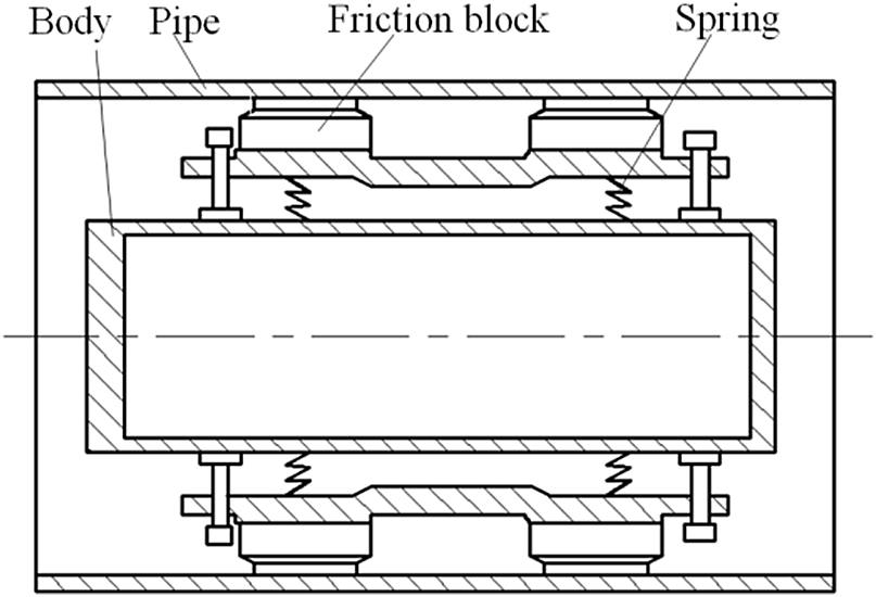
Braithwaite and Smith [Reference Braithwaite and Smith15] used the springs to control the contact force between the friction blocks and the pipe wall (Fig. 6). For instance, if the velocity is less than a value, the spring will be compressed, thus reducing the friction resistance. And, the robot velocity will increase. Ultimately, the robot can control the velocity dynamically.
A spring and a friction block used as velocity control mechanism [Reference Braithwaite and Smith15].

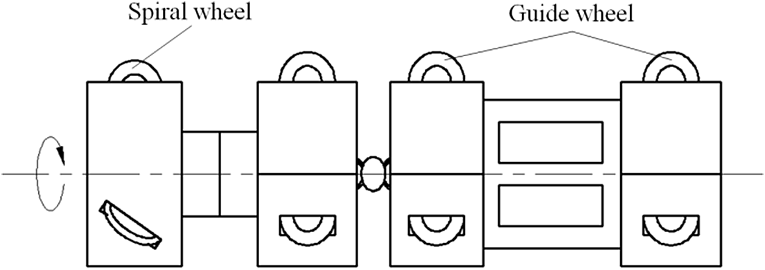
Ghorbel and Dabney [Reference Ghorbel and Dabney16] developed a LDPPR, as shown in Fig. 7. The spiral wheels contact with the pipe wall. This structure can convert the axial friction resistance of the robot into the tangential friction resistance in the direction of the spiral wheel. And, the spiral wheel simultaneously rotates and revolves. This velocity control method can greatly reduce the damage on the pipe wall produced by the friction blocks.
A spiral wheel used as velocity control mechanism [Reference Ghorbel and Dabney16].

The principle of the friction resistance type of the velocity control is that the robot can increase or reduce the friction resistance if the velocity changes. Then, the robot velocity will be controlled within a certain range of fluctuations. The velocity control method by the friction resistance may cause a great damage to the pipe wall. In this case, the driving force type of the velocity control method is much more acceptable.
2.2.2. Velocity controlled by the driving force
The velocity controlled by the driving force relies on the pressure difference between the two ends of the LDPPR. So, the robot does not damage the pipe wall. The principle of the velocity controlled by the driving force is: step 1: the inspection devices of the velocity (such as travel wheels) inspect the robot velocity in real time. Step 2: the throttle valve adjusts its opening according to the data of the velocity feedback. And, the opening of valve can directly affect the pressure difference between the two ends of the LDPPR. Therefore, the velocity controlled by the driving force can also control the robot velocity within a certain range.
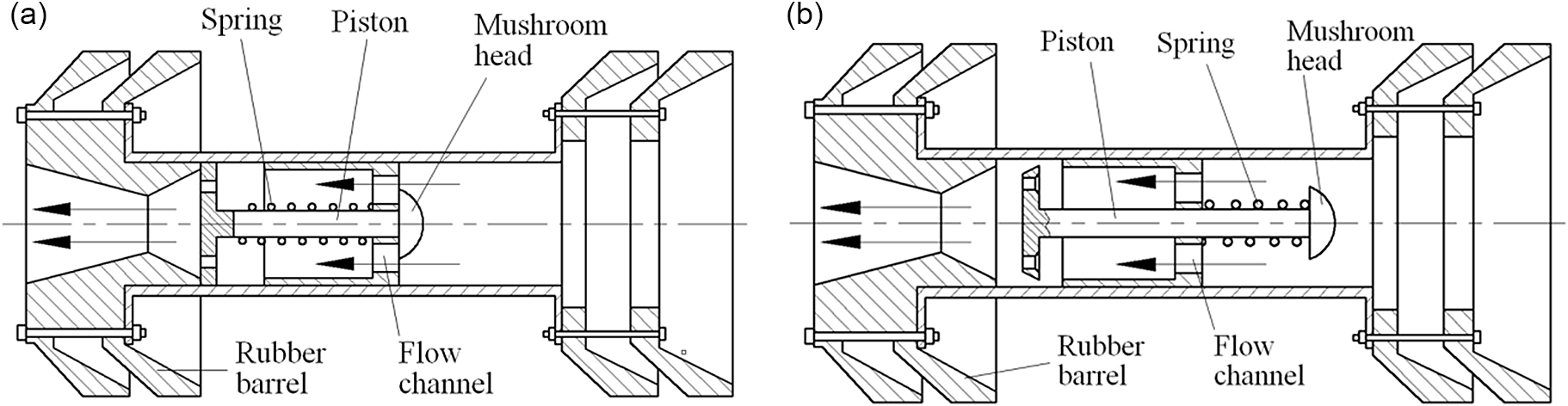
Lavine et al. [Reference Lavine, Gómez and Perez17] invented a LDPPR with a method of the velocity control. The core structures are a piston, a spring, and a mushroom head (Fig. 8a). When the flow rate is small, the flow channel aperture controlled by the mushroom head will decrease. And, the throttling effect produced by the mushroom head will increase. The increased throttling effect can increase the pressure difference between the two ends of the robot. Ultimately, the driving force and velocity of the robot will increase. This method of the velocity control is purely mechanical and passive, and the accuracy of the velocity control is very low. Pruett et al. [Reference Pruett, Strong, Freeman, Cooper, Nelson and Henault18] proposed a similar structure, as shown in Fig. 8b. The difference is that the spring is installed in different position.
A piston with mushroom head used as a driving force adjustment mechanism [Reference Lavine, Gómez and Perez17].

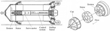
Campbell and Varney [Reference Campbell and Varney19] used a stator-rotator mechanism to control the robot velocity, as shown in Fig. 9. When the fluid flows through the stator, it can produce a throttle effect. The robot uses a servo motor to control the rotator’s position to control the size of the flow path, thus adjusting the throttling effect. The throttling effect can directly affect the pressure difference between the two ends of the robot. Then the robot can indirectly control the velocity.
A stator and a rotor used as a driving force adjustment mechanism [Reference Campbell and Varney19].

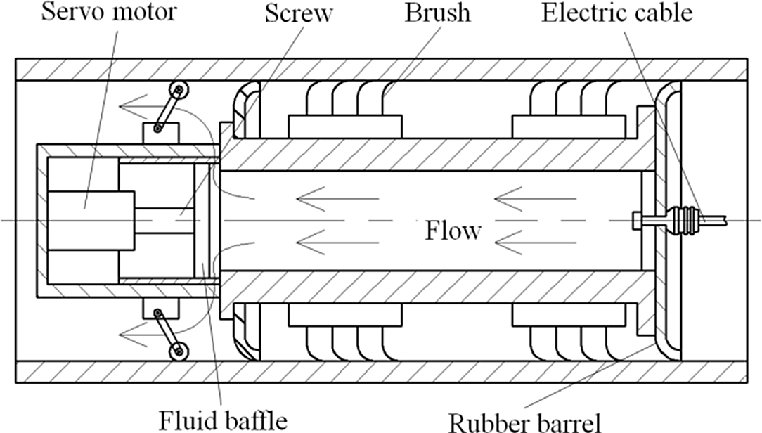
Smith et al. [Reference Smith, Couchman and Jones20] proposed a velocity-controllable LDPPR, as shown in Fig. 10. Instead of controlling the circumference size of the flow channel, the robot gets the throttling effect by adjusting the axial size of the flow channel. And, the flow channel can be changed by the motor-drive screw.
A screw and a fluid baffle used as a driving force adjustment mechanism [Reference Smith, Couchman and Jones20].

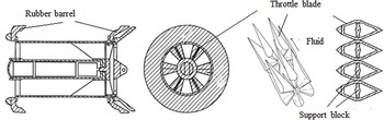
Torres et al. [Reference Torres, Manzak and Miller21] invented an adjustment mechanism to control the velocity of the LDPPR, as shown in Fig. 11. The mechanism has two sets of throttling blades, and each set of throttling blades evenly distributes circumferentially and axially. The throttle blades are internally equipped with several support blocks. When the support blocks rotate, the throttling blades can adjust the size of the flow path, resulting in a change in the throttling effect. When the velocity is too low, the support block will rotate to make the throttle blade change to be thicker. Then it can increase the throttling effect, and the pressure difference between the two ends of the robot will increase. Ultimately, the velocity can increase. When the thickness of the throttle blades reduces, the velocity can reduce.
Throttle blade used as a driving force adjustment mechanism [Reference Torres, Manzak and Miller21].

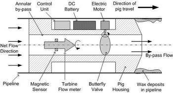
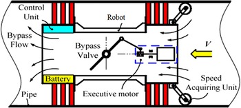
Yardi [Reference Chaitanya22] invented a LDPPR, as shown in Fig. 12. The velocity is inferred by the turbine flow meter. And, the control unit will control the opening of the butterfly valve according to the turbine flow meter. Then the driving force will change if the butterfly valve rotates. Tan et al. [Reference Bin, Min and Xiao23] also invented a LDPPR controlled by the butterfly valve, as shown in Fig. 13. Unlike the robot shown in Fig. 12, the motor of the butterfly valve is installed in different position.
Butterfly valve used as a driving force adjustment mechanism [Reference Chaitanya22].

Butterfly valve used as a driving force adjustment mechanism [Reference Bin, Min and Xiao23].

It is found that only the rubber barrel or travel wheels can contact on the pipe wall when the LDPPRs are working. Therefore, the robot does not damage the pipe wall. And, the throttle effect is easy to be controlled, which can provide an accurate velocity.
2.2.3. Velocity controlled by the self-running
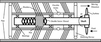
Hu and Appleton [Reference Hu and Appleton24, Reference Appleton and Stutchbury25] invented a LDPPR with a self-running mechanism (Fig. 14). The robot converts the fluid kinetic energy into mechanical energy by a turbine. The turbine rotates to drive a double screw thread. And, a nut connected with the screw thread can be moved axially. Then, the nut can drive the friction brushes to produce a continuous crawling motion.
Self-running robot with a nut-double screw thread mechanism [Reference Hu and Appleton24].

There is a principle about the self-running robot: the larger flow rate, the faster rotate velocity of the turbine, and the higher velocity. If the robot has no function of the velocity feedback, once such a robot is put into use, the velocity cannot be controlled. If the robot has the function of the velocity feedback, the velocity controlled by the self-running will have a serious time lag. For example, if the velocity needs to increase, the flow rate must increase at the inlet where is far away from the robot. Thus, the distance between the robot and the inlet can determine the response time of the velocity.
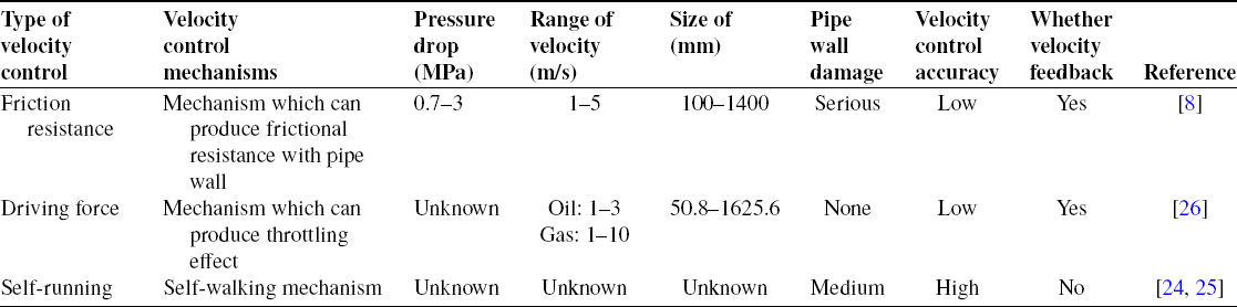
There are many types of velocity control for the LDPPRs, and the principle of each method has its own characteristics. Velocity controlled by the friction resistance and driving force are the indirect methods. When the fluid velocity is less or greater than a threshold value, the function of the velocity control is invalid. Table I shows the performances of the velocity-controllable LDPPRs.
Performance comparison of the velocity-controllable LDPPRs.

As shown in Table I, the velocity controlled by the driving force has no damage to the pipe wall. The accuracy of the velocity controlled by the driving force is better than that of the friction resistance type of the LDPPRs and self-running type of the LDPPRs. With the increasing length of the pipeline, it is necessary to get more accurate geometrical parameters and the position of the pipeline. This requires more stable and accurate method of the velocity control, which can enhance the continuity and reliability of the inspection data. The velocity control of the LDPPRs is the key to the success of pipeline inspection, so the accurate velocity control methods and mechanisms will be the core development direction in the future.
3. Mechanical models of the LDPPRs
The driving force of the LDPPRs comes from the fluid. In order to generate a sufficient driving force, the robot is usually equipped with a rubber barrel used as a seal. Therefore, the mechanical properties of the rubber barrel can determine the mechanical properties of the LDPPRs. Based on the shape of the rubber barrel, the mechanical model of the LDPPRs can be classified into the mechanical model of spherical robot and the mechanical model of cylinder robot. In addition, due to the changes in the size of the pipeline, the friction resistance, and other factors, the velocity will change at any time. Therefore, this paper will present the mechanical models including the dynamic models of the velocity-uncontrollable LDPPRs, velocity-controllable LDPPRs and the vibration, and the contact mechanics of the rubber barrels.
3.1. Dynamic models of the velocity-uncontrollable LDPPRs
3.1.1. Spherical type of LDPPR
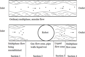
The spherical type of LDPPR was firstly used in 1958 [Reference Alvis and Ovid27]. And, this kind of LDPPR is usually used to remove the wax and hydrate inside the pipeline. Strictly speaking, this kind of so-called robot is not a robot. It is usually called “pig” because it sounds like a pig when it is working. The biggest problem of this robot is that it can be stuck when it is working. So it is important to know the mechanics and motion situation. McDonald and Baker [Reference Alvis and Ovid27] proposed a dynamic model of the spherical type of LDPPR, which divided the fluid around the robot into four sections. They are multiphase flow reestablishing section, gas flow zone and pipe wall liquid wet section, liquid flow zone section, and multiphase flow zone section, as shown in Fig. 15. The robot velocity cannot be acquired directly. However, the liquid holdup, liquid velocity, gas velocity, and pressure drop are calculated which can provide a method for the calculation of the robot velocity.
Mechanical model of sphere with four sections [Reference Alvis and Ovid27].

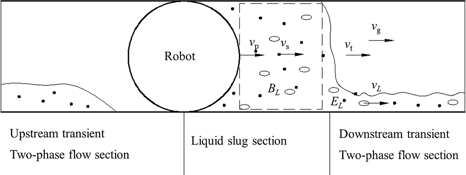
Different from the mechanical model proposed by McDonald and Baker [Reference Alvis and Ovid27], Minami and Shoham [Reference Kazuioshi and Ovadia28] divided the fluid around the robot into three sections. They are upstream transient (two-phase flow section), liquid slug section, and downstream transient (two-phase flow section), as shown in Fig. 16.
Mechanical model of sphere robot with three sections [Reference Kazuioshi and Ovadia28].

The robot velocity was deduced based on the fluid dynamic model, as shown in Eq. (2).
 \begin{equation} \rho _{\mathrm{l}}v_{\mathrm{s}}\left(v_{\mathrm{t}}-v_{\mathrm{p}}\right)E_{\mathrm{ls}}A+\rho _{\mathrm{l}}v_{\mathrm{l}}\left(v_{\mathrm{l}}-v_{\mathrm{t}}\right)E_{\mathrm{l}}A=\left(p_{\mathrm{p}}-p_{\mathrm{f}}\right)A-\mathrm{g}\rho _{\mathrm{s}}A\left(z_{\mathrm{f}}-z_{\mathrm{p}}\right)-\unicode{x03C0} \tau _{\mathrm{s}}dL_{\mathrm{s}} \end{equation}
where
 $\rho$
l is the liquid density, v
s is the velocity of the liquid slug section, v
t is the slug front translational velocity, v
p is the robot velocity, E
ls is the liquid holdup in the slug body, A is the pipe cross-sectional area, v
l is the liquid-phase velocity ahead of the slug front, E
l is the liquid holdup, P
p is the pressure at the robot position, P
f is the pressure at the slug front, g is the gravity acceleration,
 $\rho$
s is the density of the slug section, z
p and z
f are the pipe elevation at the robot and slug front positions, respectively, τ
s is the shear stress of the liquid slug section, d is the pipe diameter, and L
s is the length of the liquid slug section.
The boundary condition of the robot is also the boundary condition of the fluid. In order to make the calculation simpler and faster, Hosseinalipour et al. [Reference Hosseinalipour, Salimi and Zarif29] simplified the continuum equation and momentum equation, as shown in Eqs. (3) and (4), respectively.
 \begin{align}\begin{cases} \dot{m}_{g}=\rho _{g}Q_{g}=\rho _{g}v_{g}A_{g}\\ \\[-9pt]\dfrac{\partial \left(\rho _{1}A_{1}\right)}{\partial t}+\dfrac{\partial \left(\rho _{1}A_{1}v_{1}\right)}{\partial x}=0 \end{cases}\end{align}
 \begin{equation} \left\{\begin{array}{l} \dfrac{1}{\rho _{\mathrm{l}}}\dfrac{\mathrm{d}P}{\mathrm{d}x}+\dfrac{C_{\mathrm{wl}}}{y_{\mathrm{l}}}v_{\mathrm{l}}\left| v_{\mathrm{l}}\right| -C_{\mathrm{i}}\dfrac{\rho _{\mathrm{g}}}{\rho _{\mathrm{l}}y_{\mathrm{l}}}\left(v_{\mathrm{g}}-v_{\mathrm{l}}\right)\left| v_{\mathrm{g}}-v_{\mathrm{l}}\right| +\mathrm{g}\sin \theta =0\\ \\[-9pt] \dfrac{1}{\rho _{\mathrm{g}}}\dfrac{\mathrm{d}P}{\mathrm{d}x}+\dfrac{C_{\mathrm{wg}}}{1-y_{\mathrm{l}}}v_{\mathrm{g}}^{2}+\dfrac{C_{\mathrm{i}}}{1-y_{\mathrm{l}}}\left(v_{\mathrm{g}}-v_{\mathrm{l}}\right)\left| v_{\mathrm{g}}-v_{\mathrm{l}}\right| +\mathrm{g}\sin \theta =0 \end{array}\right. \end{equation}
where m
g
is the gas mass flow rate,
 $\rho$
g is the gas density, Q
g
is the volumetric gas flow rate, v
g is the gas velocity, A
g is the cross sections which is occupied by gas,
 $\rho$
l is liquid density, A
l is the cross sections which is occupied by liquid, v
l is the liquid velocity, x and t are the axial and time coordinates, P is the pressure, C
wg, C
wl, C
i are the gas, liquid, and interfacial shear coefficients, and y
l is the liquid holdup.
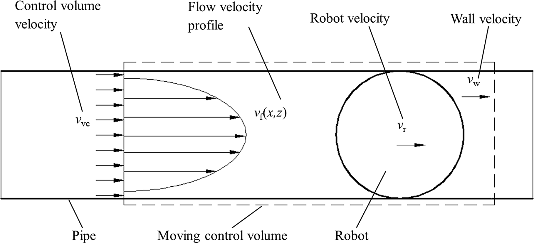
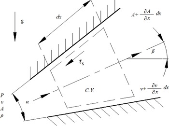
Parilli et al. [Reference Diego, Nelson, Janneth and Armando30] created a dynamic model of the spherical type of LDPPR with the moving control volume method, as shown in Fig. 17. The moving volume control method can simplify the calculation process.
Mechanical model of spherical robot with moving control volume method [Reference Diego, Nelson, Janneth and Armando30].

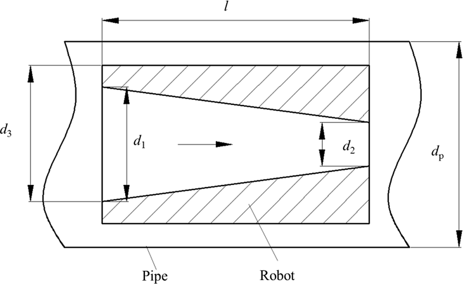
Mechanical model of the pipeline robot with the finite difference method [Reference Jean31].

3.1.2. Cylindrical type of LDPPR
Sullivan [Reference Jean31] proposed a dynamic model about the cylinder type of LDPPR, as shown in Fig. 18. The flow path of the robot is designed to be a conical hole. The hydrodynamic equations of the internal channel and annular space of the robot are established, as shown in Eq. (5). The hydrodynamic equations and the motion equations can form the nonlinear differential equations, and the robot velocity can be calculated by the finite difference method.
 \begin{equation}m\ddot{x}=P^{+}A^{+}-P^{-}A^{-}+\overline{P_{h}}\left(A^{-}-A^{+}\right)-F_{h}-F_{a}\end{equation}
where m is the mass of the robot,
 $\ddot{x}$
is the acceleration of the robot, P
+ is the pressure immediately upstream of the robot, A
+ is the upstream cross-sectional area of the robot, P
– is the pressure immediately upstream of the robot, A
– is the downstream cross-sectional area of the robot, P
h is an average pressure of the gas in the hole, F
h is the frictional force exerted on the robot by the gas in the hole, and F
a is the frictional force exerted on the outside of the robot.
Azevedo et al. [Reference Azevedo, Braga, Nieckele and Naccache32] established a dynamic model of the LDPPR, as shown in Eq. (6). Although this dynamic model is very simple, it is useful.
 \begin{equation} \left\{\begin{array}{l} \unicode{x03C0} R^{2}\Delta P+2\unicode{x03C0} RL\left(\dfrac{\Delta P}{2L}\delta -\dfrac{\mu v_{\mathrm{r}}}{\delta }\right)=F_{\mathrm{fr}}\\ \\[-6pt] Q_{\mathrm{bp}}=Q_{\mathrm{g}}+Q_{\mathrm{h}}=2\unicode{x03C0} R\left(\dfrac{\delta ^{3}\Delta P}{12\mu L}-\dfrac{\delta v_{\mathrm{r}}}{2}\right)+\dfrac{\unicode{x03C0} \sqrt{2}D^{2}}{4}\sqrt{\dfrac{D\Delta P}{\left(Dk+fl\right)\rho }}=Q-\unicode{x03C0} R^{2}v_{\mathrm{r}} \end{array}\right. \end{equation}
where R is the internal radius of the pipe, ΔP is the drive pressure, L is the length of the robot in contact with the wall, δ is the thickness of an idealized uniform gap between the robot surface and the pipe wall, μ is the dynamic viscosity of the fluid, v r is the robot velocity, Ffr is the friction force between the robot and the pipe wall, Q bp is the total bypass flow, Q g is the net bypass flow through the effective gap, Q h is the bypass flow through the hole, D is the hole diameter, k is a factor that takes into account energy losses in the entrance and exit of the hole, f is the pressure drop coefficient associated with the fully developed flow in the bypass port, and l is the length of robot.
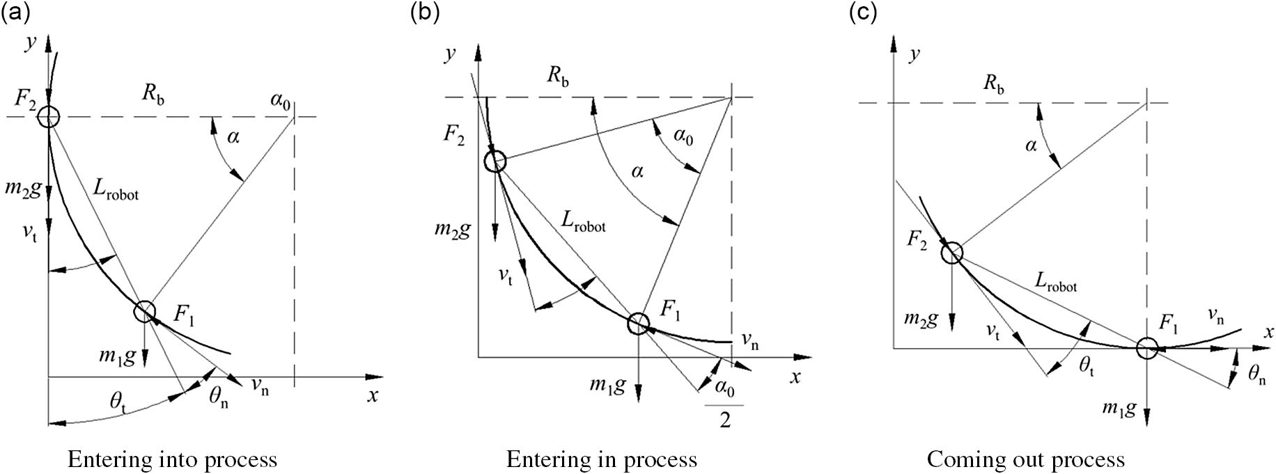
Nguyen et al. [Reference Tien, Kyu, Woo and Bong33] simplified the robot into two particles (Fig. 19). And, the dynamic model when passing through the curved pipe is established. What is more, it is divided into three sections (entering into process, entering in process, coming out process) in the curve section (90°).
Mechanical model of the pipeline robot with the concentrated mass method [Reference Tien, Kyu, Woo and Bong33].

The equations for the three sections are deduced, respectively, as shown in Eqs. (7), (8) and (9).
 \begin{equation}\ddot{\alpha }+\frac{m_{2}Y\frac{\partial Y}{\partial \alpha }}{m_{1}R_{b}^{2}+m_{2}Y^{2}}\dot{\alpha }^{2}=\frac{-4m_{1}gR_{b}\mathit{\sin } \alpha -\left(2p_{n}A+F_{fp}\right)R_{b}\mathit{\cos } \theta _{n}+\left(2p_{t}A+F_{fp}\right)\mathit{\cos } \theta _{t}}{2\left(m_{1}R_{b}^{2}+m_{2}Y^{2}\right)}\end{equation}
 \begin{equation}\ddot{\alpha }=\frac{-2m_{1}g\mathit{\sin } \alpha -m_{2}g\mathit{\sin } \left(\alpha -\alpha _{0}\right)-m_{2}g\mathit{\sin } \alpha -\left(p_{n}A-p_{t}A+F_{fp}\right)\mathit{\cos } \dfrac{\alpha _{0}}{2}}{\left(m_{1}+m_{2}\right)R_{b}}\end{equation}
 \begin{equation}\ddot{\alpha }+\frac{m_{1}T\dfrac{\partial T}{\partial \alpha }}{m_{1}T^{2}+m_{2}R_{b}^{2}}\dot{\alpha }^{2}=\frac{-4m_{1}gT-4m_{2}gR_{b}\mathit{\sin } \alpha -\left(2p_{n}A+F_{fp}\right)T\mathit{\cos } \theta _{n}+\left(2p_{t}A-F_{fp}\right)R_{b}\mathit{\cos } \theta _{t}}{2\left(m_{1}T^{2}+m_{2}R_{b}^{2}\right)}\end{equation}
where
 $Y=R_{\mathrm{b}}\cos \alpha +\frac{R_{\mathrm{b}}^{2}\left(2\sin \alpha -\sin 2\alpha \right)}{2\sqrt{L_{\text{robot}}^{2}-R_{\mathrm{b}}^{2}\left(1-\cos \alpha \right)^{2}}}, T=R_{\mathrm{b}}\sin \alpha +\frac{R_{\mathrm{b}}^{2}\left(2\cos \alpha -\sin 2\alpha \right)}{2\sqrt{L_{\text{robot}}^{2}-R_{\mathrm{b}}^{2}\left(1-\sin \alpha \right)^{2}}}, \theta _{\mathrm{t}}=\sin ^{-1}\left[\frac{R_{\mathrm{b}}\left(1-\cos \alpha \right)}{L_{\text{robot}}}\right], \theta _{\mathrm{n}}=\alpha -\sin ^{-1}\left[\frac{R_{\mathrm{b}}\left(1-\cos \alpha \right)}{L_{\text{robot}}}\right], \alpha _{0}=\cos ^{-1}\left(1-\frac{L_{\text{robot}}^{2}}{2R_{\mathrm{b}}^{2}}\right)$
, α is the angle between the robot and horizontal line, m
i
is the mass of the particle i, R
b is the bending radius of curved section, g is the gravity acceleration, A is the pipe cross section, F
fp is the friction force between the robot and pipe wall, and L
robot is the length of the robot.
Hosseinalipour et al. [Reference Hosseinalipour, Khalili Zarif and Salimi34] and Nieckele et al. [Reference Nieckele, Braga and Azevedo35] established a continuum equation and momentum equation based on the compressible natural gas, as shown in Fig. 20. According to the dynamical equations of the bypass fluid, the dynamical equations are established [Eq. (10)].
 \begin{equation} m\frac{dv_{\mathrm{r}}}{dt}=\left(P_{1}-P_{2}\right)A_{\mathrm{p}}-m\mathrm{g}\sin \beta -F_{\mathrm{c}} \end{equation}
where m is the mass of the robot, v
r is the robot velocity, t is the time, P
1 and P
2 are the pressure on the upstream and downstream faces of the robot, A
p is the cross-sectional area, g is the gravity acceleration,
 $\beta$
is the angle of the pipe axis with the horizontal, and F
c is the axial contact force between the robot and the pipe wall.
Mechanical model of boundary condition with robot [Reference Hosseinalipour, Khalili Zarif and Salimi34, Reference Nieckele, Braga and Azevedo35].

For the robot with a bypass, the P 1, P 2 (the pressure at both ends of the robot) shown in Eq. (11) can be calculated by the following formula:
 \begin{equation} P_{1}-P_{2}=\frac{\rho K}{2}\left(\frac{A}{A_{\mathrm{h}}}\right)^{2}\left(\frac{Q}{A}-v_{\mathrm{r}}\right)^{2} \end{equation}
where
 $\rho$
is the density of the fluid, K is the localized pressure drop coefficient, A is the cross-sectional area of the pipe, A
h is the bypass hole cross-sectional area, Q is the rate of flow, and v
r is the robot velocity.
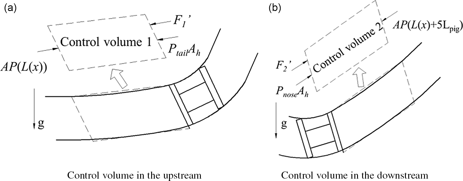
In order to calculate the forces acting on the two ends of the robot, Lesani et al. [Reference Lesani, Rafeeyan and Sohankar36] used two control volumes at the two ends of the LDPPR, as shown in Fig. 21.
Mechanical model of the pipeline robot with the control volume method [Reference Lesani, Rafeeyan and Sohankar36]

Based on the mechanical model (Fig. 21), the two-dimensional dynamic model and three-dimensional dynamic equations are given in Eqs. (12) and (13), respectively.
 \begin{align}& m\left[\frac{f'(x)f''(x)}{\sqrt{1+f'(x)^{2}}}\dot{x}^{2}+\ddot{x}\sqrt{1+f'(x)^{2}}\right]=\frac{K_{\textit{total}}\rho A\left(v-\dot{x}\sqrt{1+f'(x)^{2}}\right)^{2}}{2A_{h}}-\frac{5\rho L_{\textit{robot}}v^{2}}{2D}\nonumber \\[3pt]&\quad +\frac{f'(x)\left(4\rho gAL_{\textit{robot}}-mg\right)}{\sqrt{1+f'(x)^{2}}}-sgn\left(\dot{x}\right)m\mu \left[\frac{f''(x)\dot{x}+g}{\sqrt{1+f'(x)^{2}}}\right]\end{align}
 \begin{align}\ddot{\lambda }& =\frac{\left| \dot{\lambda }\right| }{\lambda }h_{2}\left\{\left[\dot{\lambda }^{2}\left(x'^{2}+y'^{2}+z'^{2}\right)\sqrt{a_{1}^{2}+b_{2}^{2}+c_{3}^{2}}+\frac{ga_{2}}{\sqrt{\left(x'^{2}+y'^{2}+z'^{2}\right)\left(a_{1}^{2}+b_{2}^{2}+c_{3}^{2}\right)}}\right]^{2}\right.\nonumber \\ &\quad \left.+\left[\frac{\left| \dot{\lambda }\right| g\left(a_{3}x'-a_{1}z'\right)}{\dot{\lambda }\sqrt{\left(x'^{2}+y'^{2}+z'^{2}\right)\left(a_{1}^{2}+b_{2}^{2}+c_{3}^{2}\right)}}\right]^{2}\right\}^{0.5}+\frac{gy'-\dot{\lambda }^{2}\left(x'x''+y'y''+z'z''\right)}{x'^{2}+y'^{2}+z'^{2}}\end{align}
where
 $h_{2}=\frac{1}{\sqrt{x'^{2}+y'^{2}+z'^{2}}}\left[\frac{K_{\textit{total}}\rho A^{2}\left(1-\dot{\lambda }\sqrt{x'^{2}+y'^{2}+z'^{2}}\right)}{2mA_{h}}+\frac{5fpL_{\textit{robot}}v^{2}A}{2Dm}-\frac{4\rho gAL_{\textit{robot}}\dot{\lambda }y'}{m\sqrt{\dot{\lambda }^{2}\left(x'^{2}+y'^{2}+z'^{2}\right)}}-sgn\left(\mu \dot{\lambda \sqrt{x'^{2}+y'^{2}+z'^{2}}}\right)\right]$
, m is the mass of the robot, f(x) is the function of the centerline of the robot in 2D, sgn(x) is the function of sign, K
total is the pressure drop coefficient, ρ is the density of fluid, A is the cross-sectional area, v is the velocity of the fluid, A
h is the cross-sectional area of the bypass, L
robot is the length of the robot, D is the pipeline diameter, g is the gravity acceleration, μ is the friction coefficient, and λ is a time-dependent parameter.
Solghar and Davoudian [Reference Alireza and Masoud37] established a dynamic model by considering the linear damping coefficient of the robot [Eq. (14)]. And the characteristics (MOC) is proposed to calculate the equation.
 \begin{equation} m\frac{\mathrm{d}v_{\text{robot}}}{\mathrm{d}t}+Cv_{\text{robot}}=\left(P_{\text{tail}}-P_{\text{nose}}\right)A-m\mathrm{g}\sin \beta -F_{c} \end{equation}
where m is the mass of robot, v
robot is the robot velocity, t is the time, C is the camping coefficient, P
tail is the pressure on the robot tail, P
nose is the pressure on the robot nose, g is the gravity acceleration,
 $\beta$
is the angle between robot axis and pipe axis, and F
c is the friction force between robot and pipe.
Deng et al. [Reference Deng, Gong, Zhou, Zhang and Li38] proposed that the vapor of the liquid caused by the pressure drop could influence the motion of the LDPPR. Therefore, the hydrodynamic equations with vapor and the equation of robot dynamics are established.
Mirshamsi and Rafeeyan [Reference Mirshamsi and Rafeeyan39] established a dynamic model of the LDPPR, which considered the length of the robot and the deformation of the robot, as shown in Fig. 22. The equation is deduced [Eq. (15)] based on the dynamic model of the robot. And, the particle model and dynamic model with considering the robot length are compared. The comparison results show that the mechanical model which considers the robot length is more suitable for a long-distance pipeline.
 \begin{equation} \begin{array}{l} P_{1}-P_{2}=\left[P\left(x+5L_{\text{robot}}\cos \theta \right)-P(x)\right]A+\left(P_{\text{tail}}-P_{\text{nose}}\right)A_{\mathrm{h}}+\\[3pt]2\left[\rho \left(x+4L_{\text{robot}}\cos \theta \right)\right]L_{\text{robot}}A\sin \theta +\left[\frac{\rho ^{2}(x)A^{2}}{\rho _{\mathrm{h}}A_{\mathrm{h}}}-\rho (x)A\right]\left[v(x)-v_{\text{robot}}\right]^{2}+\\[3pt]\left[-\dfrac{\rho ^{2}\left(x+5L_{\text{robot}}\cos \theta \right)A^{2}}{\rho _{\mathrm{h}}A_{\mathrm{h}}}-\rho \left(x+5L_{\text{robot}}\cos \theta \right)A\right]\left[v\left(x+5L_{\text{robot}}\cos \theta \right)-v_{\text{robot}}\right]^{2} \end{array} \end{equation}
where P
1 and P
2 are forces applied on the tail and nose of the robot, x is the horizontal displacement, L
robot is the length of robot, θ is the angle between the vertical and the axis of the robot, P(x) is the pressure in position x, P
tail is the pressure at the tail of the robot, P
nose is the pressure at the nose of the robot, A
h is the cross-sectional area of the valve,
 $\rho$
is the density of the robot, A is the cross-sectional area of the pipeline,
 $\rho$
h is the density of the fluid at the valve, and v
robot is the robot velocity.
Mechanical model considering the robot length [Reference Mirshamsi and Rafeeyan39].

Mechanical model of the pipeline robot with the control volume method [Reference Nshuti40].

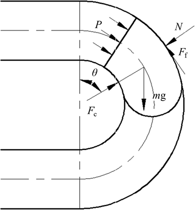
Fabrice [Reference Nshuti40] established a dynamic model when the cylindrical type of LDPPR passes through the curving pipe, as shown in Fig. 23. And the equation of dynamic model is deduced. Eq. (16) shows that the velocity is mainly determined by the mass and length of the robot, radius of the pipe, and the contact stress between the robot and the pipe wall.
 \begin{equation}\ddot{\theta }+\mu \dot{\theta }^{2}=\frac{\pi d^{2}p}{4mR}-\frac{\pi uldp_{c}}{mR}+\frac{g}{R}\left(\mathit{\sin } \theta +\mu \mathit{\cos } \theta \right)\end{equation}
where θ is the angle between the position of robot and vertical direction, μ is the friction coefficient, d is the inner diameter of the pipe, p is the fluid pressure, R is the radius of axis of curved pipe, m is the mass of the robot, R is the pipeline centerline radius, l is the robot length, p c is the interference contact pressure, and g is the gravity acceleration.
3.2. Dynamic models of the velocity-controllable LDPPRs
The velocity of the LDPPR will affect the accuracy of the inspection. In order to improve the accuracy of the inspection data, the velocity should be controlled within a certain range. And, the velocity is 1–5 m/s in liquid and 2–7 m/s in gaseous [Reference Mirshamsi and Rafeeyan41]. According to the dynamic models of the velocity-controllable LDPPRs, the robots can be subdivided into two categories: the type of velocity controlled by brake and the type of velocity controlled by bypass.
3.2.1. Velocity controlled by the brake
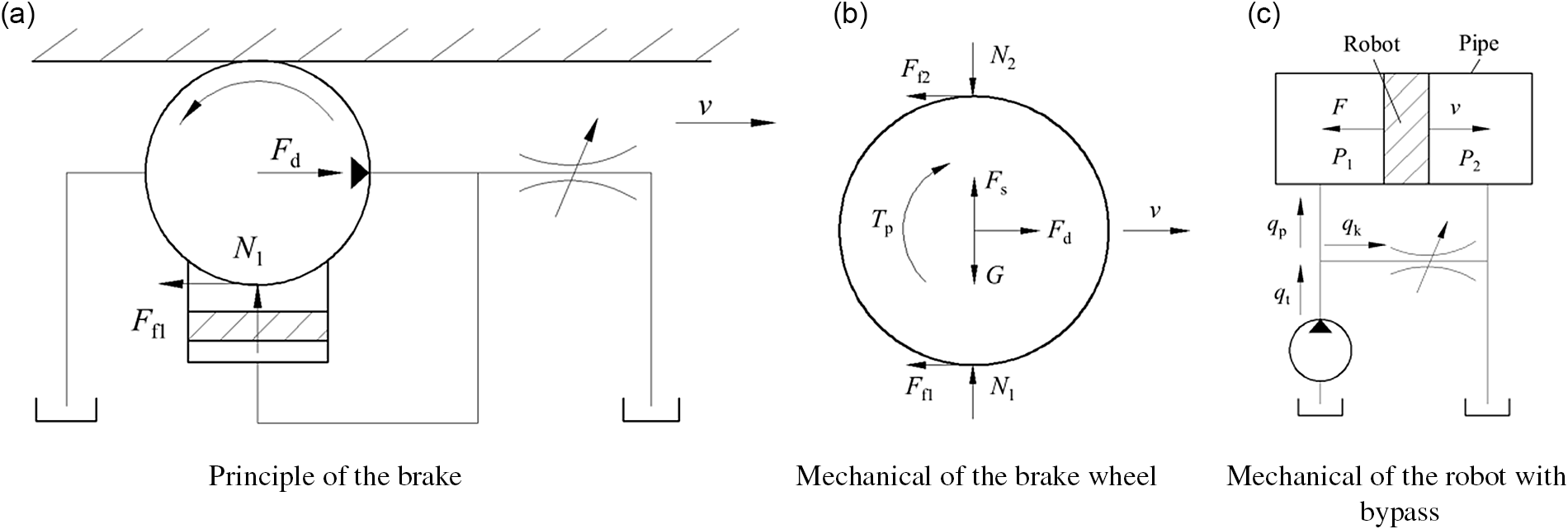
Liang et al. [Reference Liang, He and Cai42] present a LDPPR whose velocity is controlled by the brake (Fig. 24). The equation of the velocity control of the robot is derived [Eq. (17)].
 \begin{equation} \left\{\begin{array}{l} \left(m_{\mathrm{b}}+m_{\mathrm{r}}\right)v'=A_{\mathrm{p}}\left(P_{1}-P_{2}\right)-F\\ \\[-5pt]v'=\dfrac{K_{\text{total}}A_{\mathrm{p}}\rho _{\mathrm{p}}\left(q_{\mathrm{t}}-A_{\mathrm{p}}v\right)^{2}}{2A_{\mathrm{h}}^{2}\left(m_{\mathrm{b}}+m_{\mathrm{r}}\right)}-\dfrac{\mu _{1}A_{\mathrm{c}}n^{3}\rho _{\mathrm{o}}v_{\mathrm{o}}^{2}v^{2}}{\left(2\unicode{x03C0} rC_{\mathrm{t}}A_{\mathrm{t}}\right)^{2}\left(m_{\mathrm{b}}+m_{\mathrm{r}}\right)}-\dfrac{f'(x)\mathrm{g}}{\sqrt{1+f'(x)^{2}}}-\dfrac{F_{c}}{m_{\mathrm{b}}+m_{\mathrm{r}}} \end{array}\right. \end{equation}
where v is the robot velocity, A
p is the cross-sectional area of the pipe, K
total is the total flow coefficient of the bypass hole,
 $\rho$
p is the density of the liquid in the pipeline, q
t is the total flux, A
h is the cross-sectional area of the bypass, m
b is the mass of the brake unit, m
r is the mass of the robot, μ
1 is the frictional coefficient between the wheel and its brake, A
c is the cross-sectional area of the hydraulic cylinder of the brake, n is the number of wheels/pumps,
 $\rho$
o is the hydraulic oil density of the brake, v
o is the volume of hydraulic oil per pump rotation, r is the wheel radius, C
t is the flow coefficient of the throttle, A
t is the cross area of the throttle, f(x) is the function of the centerline of the pipeline, and F
c is the contact force between robot and pipe wall.
Simplified diagram of mechanical model of pipeline robot [Reference Liang, He and Cai42].

3.2.2. Velocity controlled by the bypass
Nguyen et al. [Reference Tien, Bong, Ryong and Woo43, Reference Tan, Sang, Hui and Yong44] established the dynamic equation shown in Eq. (18). In this dynamic model, the damping coefficient (C) and the elasticity coefficient (K) are considered. What is more, the pressure coefficient is divided into three sections: expansion section, contraction section, and valve section.
 \begin{equation} \left\{\begin{array}{l} m\dfrac{\mathrm{d}^{2}x_{\text{robot}}(t)}{dt^{2}}+C\dfrac{dx_{\text{robot}}(t)}{dt}+Kx_{\text{robot}}(t)=F_{\mathrm{p}}(t)-F_{\mathrm{fp}}(t)\\ \\[-9pt]K_{\text{total}}(t)=\dfrac{2g}{A\left[\nu _{\mathrm{v}}(t)-\nu _{\text{robot}}(t)\right]^{2}}\left[Kx_{\text{robot}}(t)+\left(C-mC_{1}\right)\nu _{\text{robot}}(t)+F_{\mathrm{fp}}(t)+MC_{1}\nu _{\mathrm{ref}}\right] \end{array}\right. \end{equation}
where m is the hydraulic mean radius of the pipe, x robot is the displacement of the robot, t is the time, C is the damping coefficient, K is the elasticity velocity, F p is the robot driving force, F fp is the friction force between the robot and the pipe wall, K total is the total loss coefficient, g is the gravity acceleration, A is the pipe cross-sectional area, v v is the flow velocity trough valve, v robot is the robot velocity, C 1 is the convection heat transfer coefficient, and M is the weight of the robot.
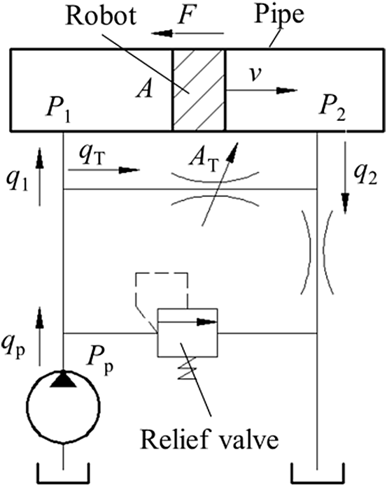
The mechanical model of the pipeline with a bypass hole [Reference Li, Jiang, Wang, Ren and Gao45].

Li et al. [Reference Li, Jiang, Wang, Ren and Gao45] invented a LDPPR whose velocity was controlled by the bypass, as shown in Fig. 25. And, this robot has a relief valve which can prevent P 1 from being too large to lose control. The dynamic equation is shown in Eq. (19).
 \begin{equation} v_{\mathrm{r}}=\frac{q_{1}}{A}=\frac{q_{\mathrm{p}}-KA_{\mathrm{T}}\left(\dfrac{F}{A}\right)^{0.5}}{A} \end{equation}
where v r is the robot velocity, q l is the flux load on the incident flow face, A is the area of piston, q p is the total flux crossing the choke, K is the constant (relate to the form of the throttle valve and viscosity of oil), A T is the flow area, and F is the friction force.
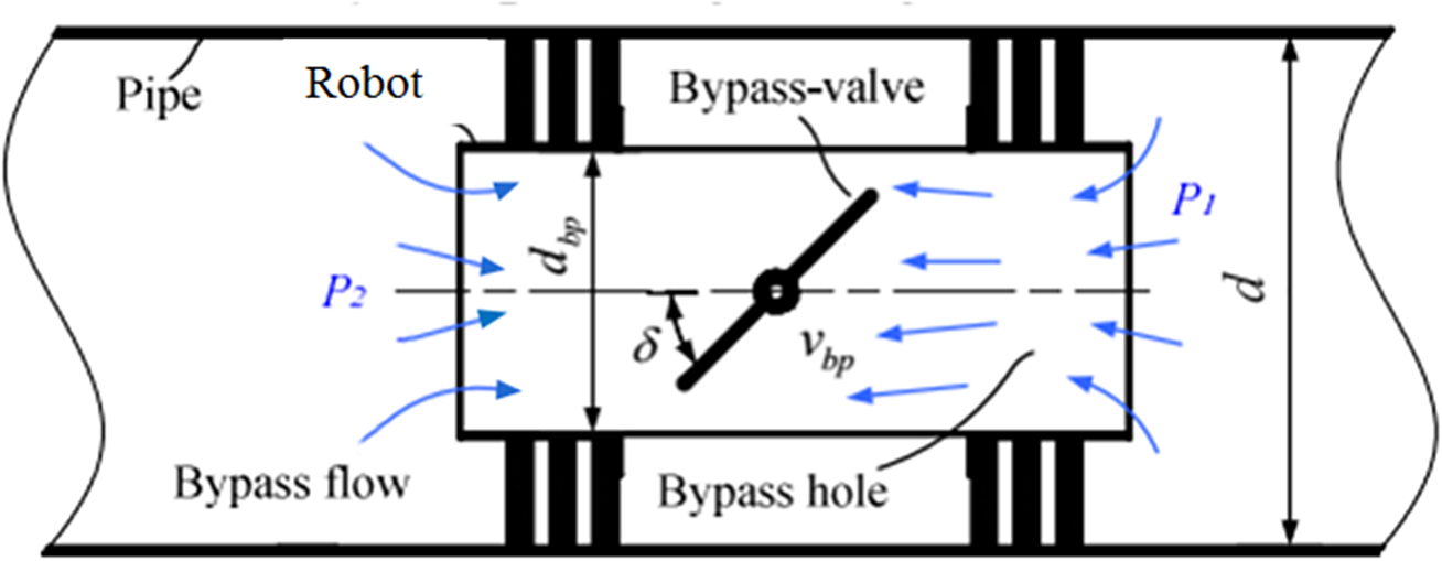
Tan et al. [Reference Bin, Min and Xiao23] invented a LDPPR with a butterfly bypass valve. The valve can adjust the opening of the fluid channel, as shown in Fig. 26. Thus, the velocity can be controlled by the butterfly bypass valve.
Mechanical model of the butterfly bypass valve in the pipeline robot [Reference Bin, Min and Xiao23].

According to the structure of the butterfly bypass valve, the dynamic equation is deduced, as shown in Eq. (20).
 {\fontsize{9}{10}\selectfont\begin{equation} \left\{\begin{array}{l} \Delta P(t)=P_{1}(t)-P_{2}(t)=\zeta _{\text{total}}\dfrac{\rho v_{\mathrm{bp}}^{2}}{2}\\ \\[-6pt]\zeta _{\text{total}}=0.5\left(1-\dfrac{d_{\mathrm{bp}}^{2}}{d^{2}}\right)+\left(1-\dfrac{d_{\mathrm{bp}}^{2}}{d^{2}}\right)^{2}+\dfrac{70}{\mathrm{Re}}\left[\dfrac{1+0.5\left(1+\sin \delta \right)}{\left(1-\sin \delta \right)^{2}}-\left(\dfrac{1.56}{1-\sin \delta }-1\right)^{2}\right]+\left(\dfrac{1.56}{1-\sin \delta }-1\right)^{2} \end{array}\right. \end{equation}}
where ΔP(t) is the differential pressure between the ends of the butterfly valve, P
1(t) is the pressure in the tail of the robot, P
2(t) is the pressure in the nose of the robot, v
bp is the velocity of the fluid in the bypass, ξ
total is the pressure loss,
 $\rho$
is the flow density in bypass hole, and δ is the rotational degree of the disc.
Mirshamsi and Rafeeyan [Reference Mirshamsi and Rafeeyan41] proposed a dynamic model called Sobhani–Rafeeyan’s model. This method replaces the nonlinear systems with the uncertain linear systems. The dynamic equation is deduced as follows:
 \begin{align}\dot{v}_{\textit{robot}}&=\frac{\left(v-v_{\textit{robot}}\sqrt{1+f'^{2}}\right)^{2}K_{\textit{total}}\rho A^{2}}{2mA_{h}\sqrt{1+f'^{2}}}-\frac{5f\rho L_{\textit{robot}}v^{2}}{2Dm\sqrt{1+f'^{2}}}+\frac{4\rho gAL_{\textit{robot}}f'}{m\left(1+f'^{2}\right)}-\frac{gf'^{2}}{1+f'^{2}}\nonumber \\[3pt] &\quad -sgn\left(\dot{x}\right)\mu \left(\frac{f'v_{\textit{robot}}^{2}+g}{1+f'^{2}}\right)-\frac{f'f''v_{\textit{robot}}^{2}}{1+f'^{2}}\end{align}
where v
robot is the robot velocity, v is the fluid velocity, f = f(x) is the centerline of the robot, K
total is the total pressure drop coefficient,
 $\rho$
is the fluid density, A is the cross-sectional area, m is the mass of the robot, A
h is the cross-sectional area of the valve, L
robot is the length of the robot, and D is the pipe diameter.
Singh and Henkes [Reference Singh and Henkes46] proposed a dynamic model about the bypass, as shown in Eq. (22). This dynamic model is very simple.
 \begin{equation} v_{\mathrm{r}}=v_{\mathrm{mix}}-\frac{2d^{2}}{D^{3}}\sqrt{\frac{2F_{\text{fric}}}{\unicode{x03C0} K\rho _{\mathrm{bp}}}} \end{equation}
where v
r is the robot velocity, v
mix is the mixture velocity, d is the bypass hole diameter, D is the pipeline diameter, K is the pressure drop coefficient,
 $\rho$
bp is the density of the bypassing fluid, and F
fric is the friction force between the robot and the pipe wall.
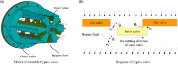
Zhu et al. [Reference Zhu, Zhang, Tan, Wang and Wang47] studied the characteristics of the rotatable type of bypass valve while the robot was working with an experiment method. The results show that the differential pressure over the bypass valve has an exponent relation with the opening of the bypass valve (Fig. 27).
Mechanical model of bypass valve [Reference Zhu, Zhang, Tan, Wang and Wang47].

The relationship between differential pressure and the opening of the bypass valve is fitted according to the experimental data, as shown in Eq. (23).
 \begin{equation} y=e^{-0.64831-15.39724x+11.06602{x^{2}}} \end{equation}
where y is the differential pressure over the bypass valve, and x is the opening of the bypass valve.
Azpiroz et al. [Reference Azpiroz, Hendrix, Breugem and Henkes48] created a dynamic model by using the method of the pressure coefficient, as shown in Fig. 28. The pressure coefficient is divided into three sections: contraction section, expansion section, and baffle disc section.
Simplified diagram of mechanical model of pipeline robot: (a) contraction, (b) expansion, and (c) baffle disc [Reference Azpiroz, Hendrix, Breugem and Henkes48].

According to the dynamic model (Fig. 28), the equation is deduced, as shown in Eq. (24). It is found that the pressure drop coefficient (4.0) of the robot with bypasses is the maximum, which is in sharp contrast with the conventional pressure drop coefficient (1.0–1.5).
 \begin{equation} \left\{\begin{array}{l} m\dfrac{dv_{\mathrm{r}}}{dt}=K\dfrac{\rho v_{L}^{2}A_{\mathrm{p}}}{2}+\sum _{i}f_{i}\\ \\[-9pt]K=0.5\left(1-\dfrac{A_{1}}{A_{0}}\right)^{0.75}+\left(1-\dfrac{A_{1}}{A_{0}}\right)^{2}+\dfrac{4fl}{d} \end{array}\right. \end{equation}
where m is the mass of robot, v
r is the robot velocity, t is the time, ΔP is the pressure loss, A
p is the cross-sectional area, f
i is the other force that may be relevant to the system, K is the pressure loss coefficient, v
L is the flow velocity inside the bypass (relative to the robot velocity),
 $\rho$
is the fluid density, A
1/A
0 is the ratio of the bypass area to the pipe area, f is the fanning friction factor, l is the length, and d is the inner diameter of the robot.
3.3. Dynamic models of the vibration
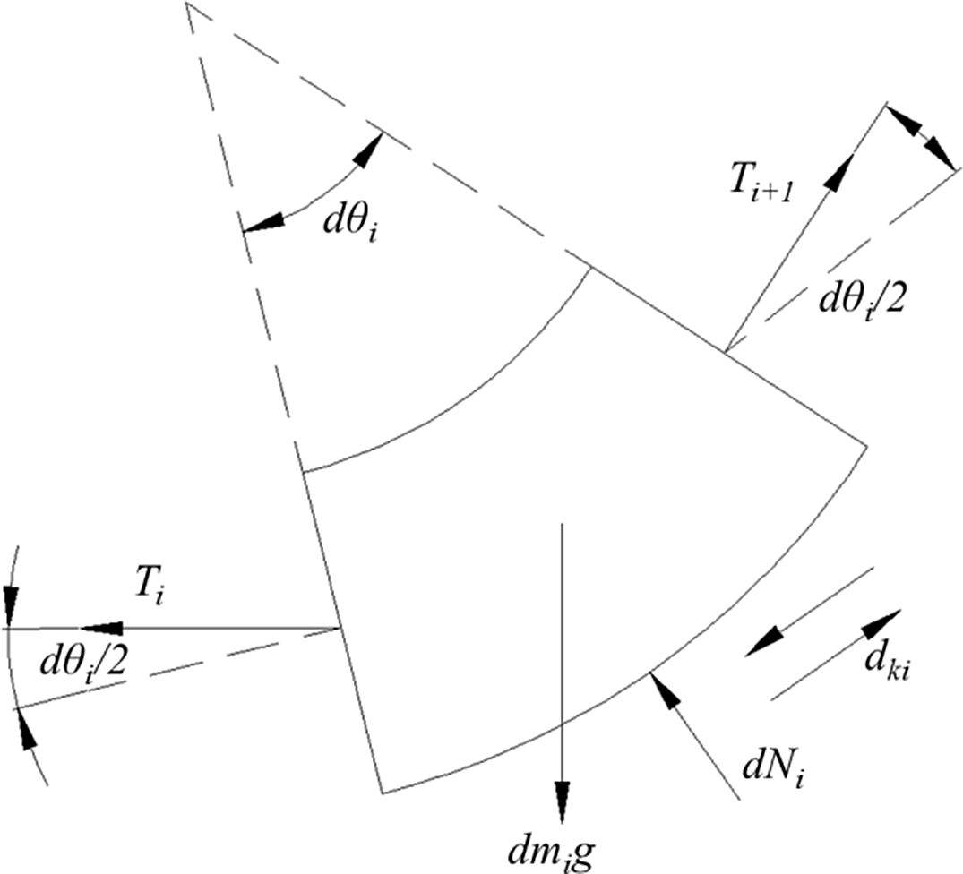
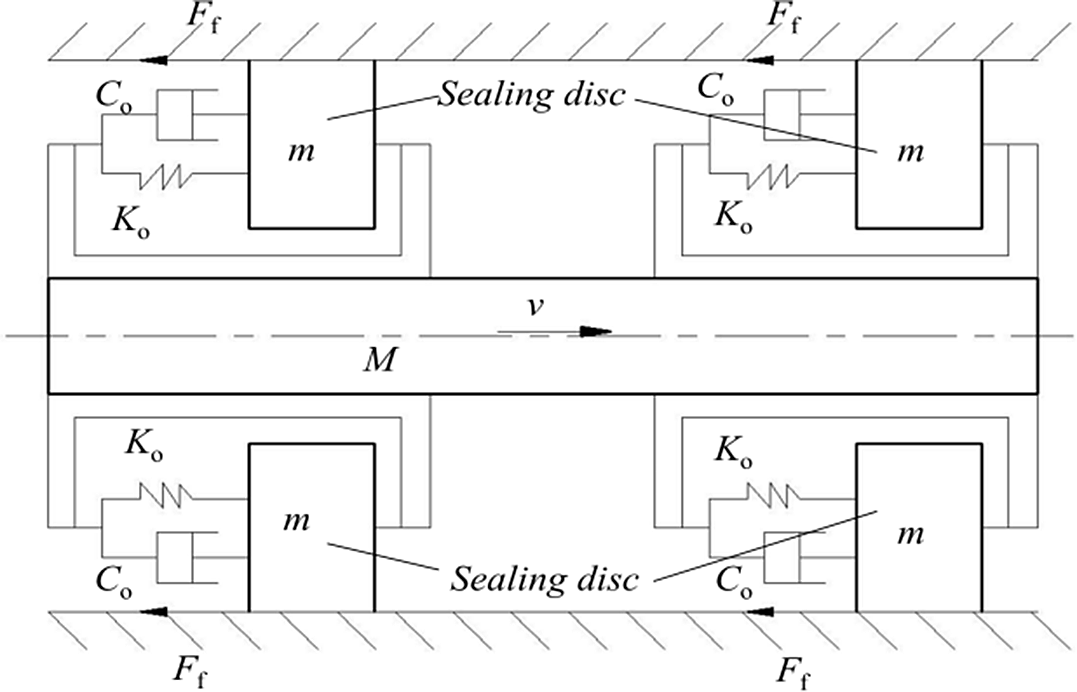
Durali et al. [Reference Mohammad, Amir and Ali49] established a dynamic model for the radial vibration, as shown in Fig. 29. Combining with the fluid continuity equation and momentum equation, the vibration regular of the LDPPR is numerically simulated when the robot passes through an obstacle of a convex sinusoidal.
Dynamic model of radial vibration of robot [Reference Mohammad, Amir and Ali49]

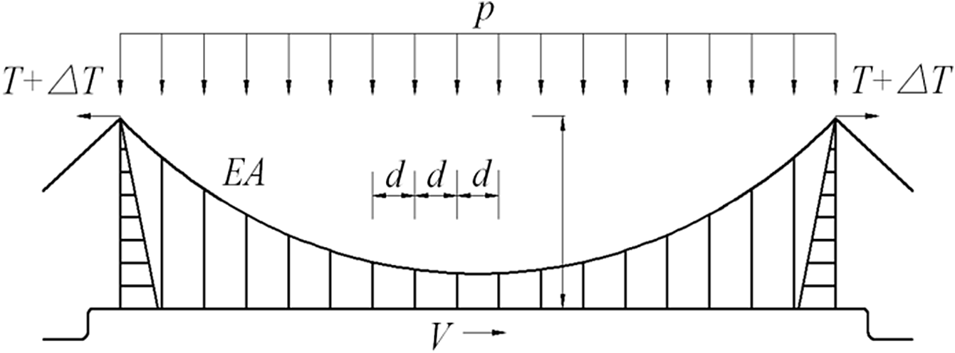
Gao et al. [Reference Gao, Wang and He50] analyzed the factors that affect the vibration performance of the LDPPR when it passed through the suspension pipe bridge and established the dynamic model of the robot (Fig. 30). The nonlinear vibration equation of the robot is deduced [Eq. (25)]. It can provide a theoretical basis for the design of the suspension bridge and the robot velocity.
 \begin{equation}\left(m+m_{l}\right)\ddot{u}+c\dot{u}+EIu^{'' ''}-\left(T+\unicode{x03B4} T\right)U''+s\int _{0}^{L}udx=g_{1}\end{equation}
where m is the total mass per unit length of the pipe, m l is the mass of the flowing liquid in the pipe, u is the additional vertical deflection caused by the robot, c is the damping coefficient, EI is the flexural rigidity of the pipe, T is the tensile forces of the two cables caused by the dead loads of the pipe and components, s is the length of the cable, x is the horizontal displacement, and g l is the weight of the flowing liquid.
Suspended pipeline bridge under robot moving loads [Reference Gao, Wang and He50].

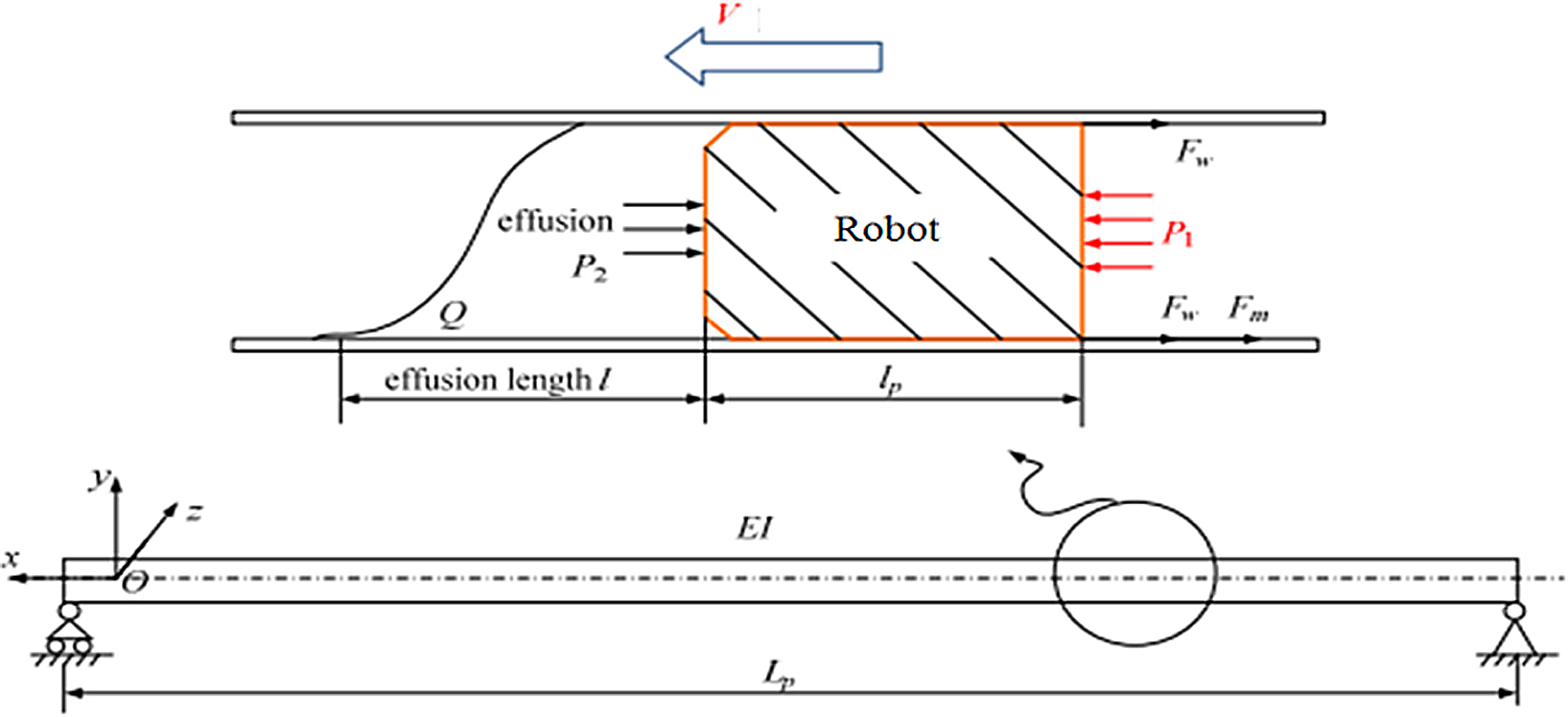
Wang et al. [Reference Ming, Min, Na and Yin51] established a dynamic model when the robot passed through a single span pipe, as shown in Fig. 31. The single span pipe is simplified as a beam model. And a vibration equation is deduced based on the dynamic model, as shown in Eq. (26).
 \begin{equation} EI\frac{\partial ^{4}y}{\partial x^{4}}+\left(m_{\mathrm{f}}v^{2}+A_{\mathrm{r}}\right)\frac{\partial ^{2}y}{\partial x^{2}}+2m_{\mathrm{f}}v\frac{\partial ^{2}y}{\partial x\partial t}+c\frac{\partial y}{\partial t}+\left(m_{\mathrm{r}}+m_{\mathrm{f}}\right)\frac{\partial ^{2}y}{\partial t^{2}}=0 \end{equation}
where EI is the flexural rigidity of the pipe, y is the vertical displacement, x is the horizontal displacement, m f is the mass per unit length of the pipe, v is the robot velocity, A r is the crossing area of the robot, m r is the mass per unit length of the robot, and t is the time.
Dynamic model of vibration of robot [Reference Ming, Min, Na and Yin51].

Zhang et al. [Reference Hang, Shimin, Shuhai, Xiaoxiao and Biao52] analyzed the factors that affect the vibration performance of the LDPPR (Fig. 32) and established the dynamic model of the axial vibration equation [Eq. (27)]. And a dominating frequency is achieved which is 15 Hz.
 \begin{equation}m\ddot{x}+\left(c_{0}+\sigma _{2}F_{N}\right)\dot{x}+\left(\mu _{s}-\mu _{c}\right)F_{N}e^{\_ {\left(\frac{\dot{x}}{v_{s}}\right)^{2}}}+K_{0}x=0\end{equation}
where m is the mass of robot, x is the horizontal direction displacement of the block in the single degree freedom model, C 0 is the axial damping of sealing disc, σ 2 is the damping coefficients that relate to the kinetic states, F N is the normal force, μ s is the kinetic friction coefficients, μ c is the static friction coefficients, ν s is the Stribeck’s velocity, and K 0 is the axial stiffness of sealing disc.
Dynamic model of axial vibration of robot based on the rubber barrel [Reference Hang, Shimin, Shuhai, Xiaoxiao and Biao52].

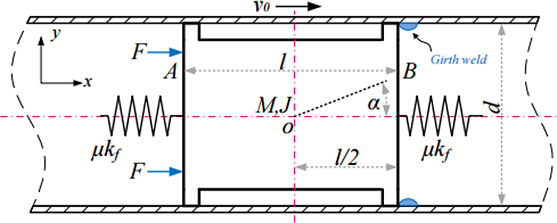
Zhang et al. [Reference Hang, Simin, Shuhai and Yan53] established a dynamic model of axial vibration base on the obstacle produced by the weld, as shown in Fig. 33. The vibration equation is deduced, as shown in Eq. (28). It is found that the influence of welding on robot vibration can be reduced by changing the damping coefficient of the rubber barrel. And, the position of the robot can be calibrated by the vibration characteristics.
Dynamic model of axial vibration of robot based on the weld [Reference Hang, Simin, Shuhai and Yan53].

 \begin{equation} x(t)=\frac{v_{0}}{2\omega \sqrt{n^{2}-1}}\left[e^{\left(-n+\sqrt{n^{2}-1}\right)\omega t}-e^{\left(-n-\sqrt{n^{2}-1}\right)\omega t}\right] \end{equation}
where x is the horizontal displacement, v 0 is the initial speed of robot, x is the horizontal direction displacement of the block in the single degree freedom model, C 0 is the axial damping of sealing disc, σ 2 is the damping coefficients that relate to the kinetic states, F N is the normal force, μ s is the kinetic friction coefficients, μ c is the static friction coefficients, ν s is the Stribeck’s velocity, and K 0 is the axial stiffness of sealing disc.
3.4. Contact mechanics of the rubber barrel
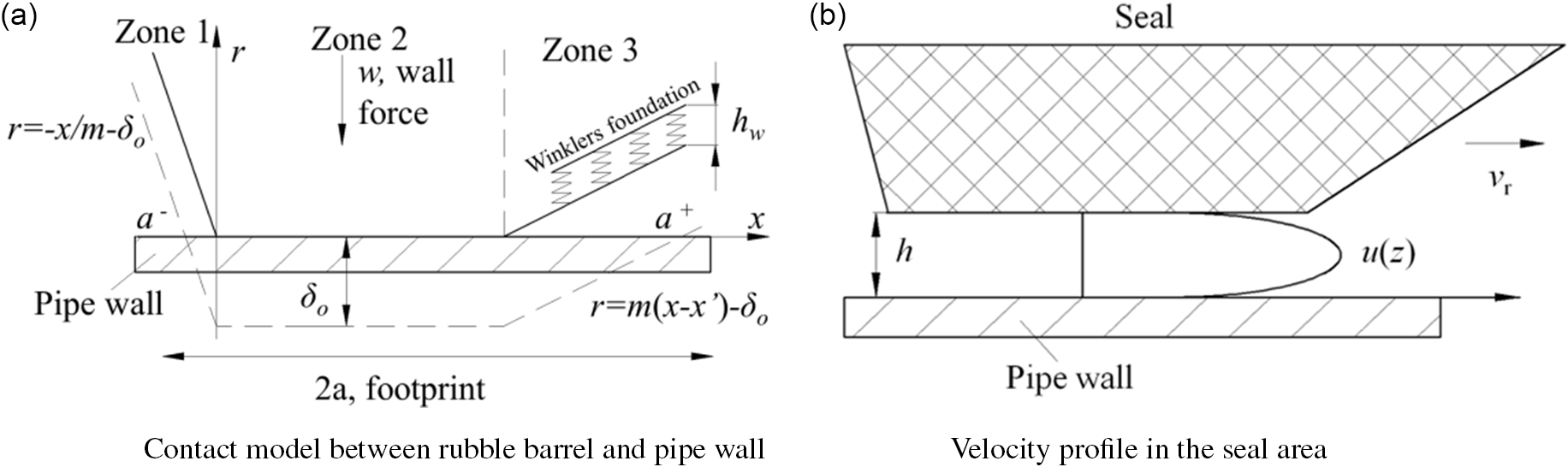
O’Donoghue [Reference Aidan54] created a contact model by using the rubble barrel and the pipe wall, as shown in Fig. 34a. On the basis of the contact model, the leakage and lubrication are analyzed. And the wear of the rubble barrel is also analyzed, as shown in Fig. 34b.
Velocity profile in seal area [Reference Aidan54].

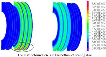
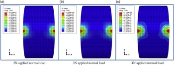
Li et al. [Reference Li, Chen, Zhang, Hu and He55] and Zhang et al. [Reference Xing, Yan, Shiming and Kang56] analyze the mechanical properties of the rubber barrel of the straight plate robot by using the numerical method, as shown in Figs. 35 and 36. The optimized parameters such as the thickness and the outer diameter of the disc are analyzed.
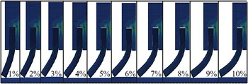
Displacement on the rubber barrel when the robot is moving forward [Reference Li, Chen, Zhang, Hu and He55].

Contact force of the rubble barrel with variable interference [Reference Xing, Yan, Shiming and Kang56].

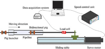
Zhu et al. [Reference Zhu, Wei, Shimin and Shuhai57] analyze the variation of the frictional resistance of the rubber barrel at different velocities and different interferences through an experimental method (Fig. 37). The results provide an effective theoretical basis for the velocity control of the LDPPR.
Schematic diagram of the experimental platform [Reference Zhu, Wei, Shimin and Shuhai57].

From the microscopic perspective, Zhang et al. [Reference Hang, Carlos, Shuhai, Shimin and Hong58] analyze the mechanism of wear, oxidation, and fatigue on the contact surface by means of microscope and finite element analysis (Fig. 38).
Stress of the rubber barrel [Reference Hang, Carlos, Shuhai, Shimin and Hong58].

4. Control algorithm of the LDPPRs
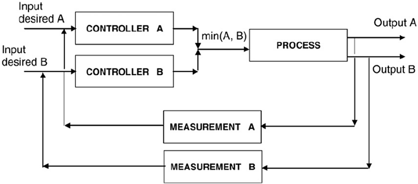
Tolmasquim and Nieckele [Reference Tolmasquim and Nieckele59] develop a numerical code control program based on the finite element difference method, which can simulate the two-fluid transient flow. The PID controller system of the robot is proposed, as shown in Eq. (29). And a controller is invented based on the pressure (A) and the velocity (B) of the robot, as shown in Fig. 39. In this controller, the valve can be controlled by both on the inlet and outlet.
 \begin{equation} u(t)=K\left[e(t)+\frac{1}{T_{1}}\int _{0}^{t}e(t)\mathrm{d}\tau +T_{\mathrm{D}}\frac{\mathrm{d}e(t)}{\mathrm{d}t}\right] \end{equation}
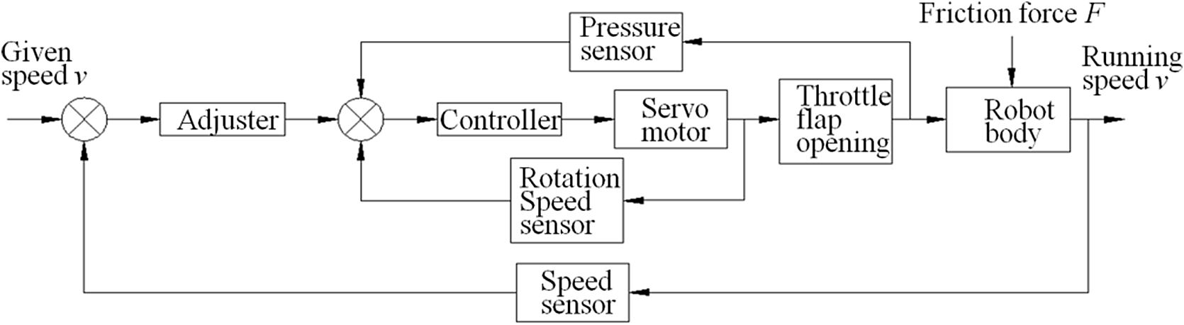
Li et al. [Reference Li, Jiang, Wang, Ren and Gao45] propose a dual closed-loop control method for the LDPPR, as shown in Fig. 40. The control objective is the robot velocity and the pressure of the fluid. What is more, the robot velocity is the outer loop and the pressure of the fluid is the inner loop.
Control system in a closed loop [Reference Tolmasquim and Nieckele59].

The control system diagram of the pipeline robot [Reference Li, Jiang, Wang, Ren and Gao45].

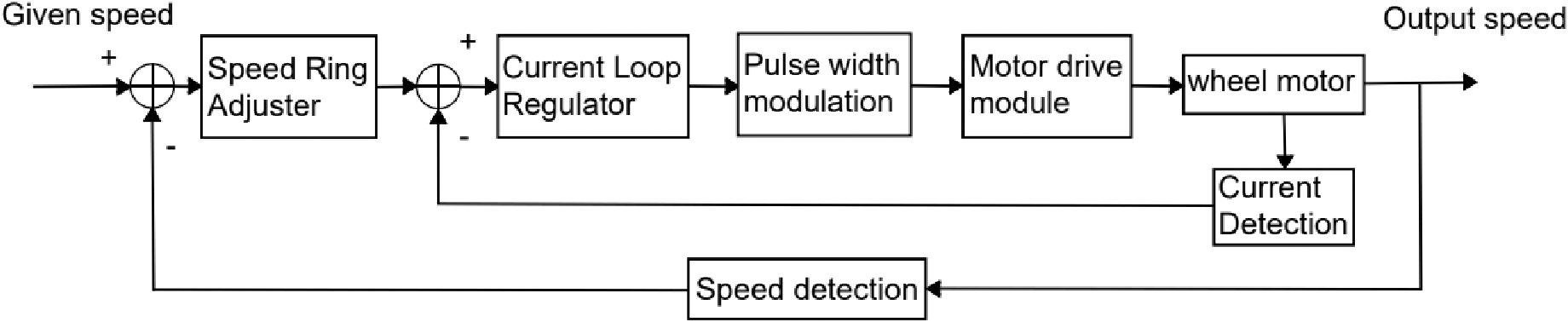
Luo et al. [Reference Jiman, Lulu, Hui and Zeming60] proposed a dual closed-loop DC speed regulation control system based on fuzzy control algorithm, as shown in Fig. 41, to control the speed of the pipeline robot and improve its dynamic performance. Among them, the current loop controller adopts the traditional PID control algorithm, and the speed loop controller adopts the adaptive fuzzy PI control algorithm, which combines the PI algorithm and the fuzzy control system, identifies the control effect through the fuzzy controller, and then automatically corrects the control parameters of the PI algorithm, thereby greatly improving the anti-interference of the control system.
Double closed-loop control system based on fuzzy control algorithm [Reference Jiman, Lulu, Hui and Zeming60].

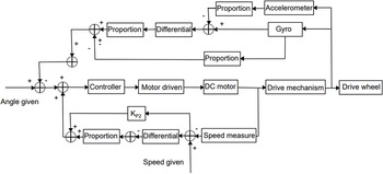
Tan [Reference Guoying61] proposed a set of walking control algorithm for LDPPR, as shown in Fig. 42. The control algorithm adopts two closed-loop controls, which are divided into attitude feedback control algorithm and speed feedback control algorithm, which are mainly used to grasp and control the running attitude and running speed of the robot.
Walking control algorithm diagram of the robot [Reference Guoying61].

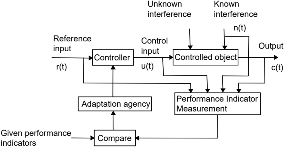
Zhang [Reference Weijie62] proposed the use of an adaptive control system to meet the control requirements of LDPPR, as shown in Fig. 43, which can automatically adjust the parameters of the controller and has a certain adaptability. The adaptive control system applies modern control theory, can identify changes in environmental conditions and system state online, make decisions by comparing with the expected control indicators, and can continuously update the controller parameters to achieve the optimum.
Adaptive control system diagram of the robot [Reference Weijie62].

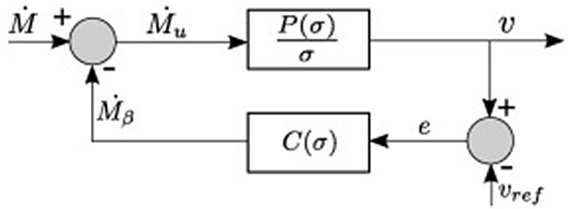
Hebdrix et al. [Reference Hendrix, IJsseldijk, Breugem and Henkes63] proposed to construct a feedback loop with a linear controller C(σ) under low pressure conditions, as shown in Fig. 44; the mechanism relies on actively regulating the size of the bypass, such that part of the pressure in the gas pocket upstream of the pig can be released. The purpose is to make the speed of the LDPPR not offset, close to or equal to the preset reference speed v, the controller adopts the PD controller:
 \begin{equation}\mathrm{C}(\unicode{x03C3} )=\mathrm{Kp}+\mathrm{Kd}\unicode{x03C3}\end{equation}
where P(σ) is the corresponding transfer function of the state-space model,
 $\mathrm{P}(\unicode{x03C3} )=\unicode{x03C3} \text{veqw}2\dot{\mathrm{M}}\unicode{x03C3} 2+\mathrm{w}2$
,
 $\mathrm{w}$
is the local angular frequency of the oscillation,
 $\unicode{x03C3}$
is the complex frequency variable, and M is the mass.
Feedback loop with a linear controller [Reference Hendrix, IJsseldijk, Breugem and Henkes63].

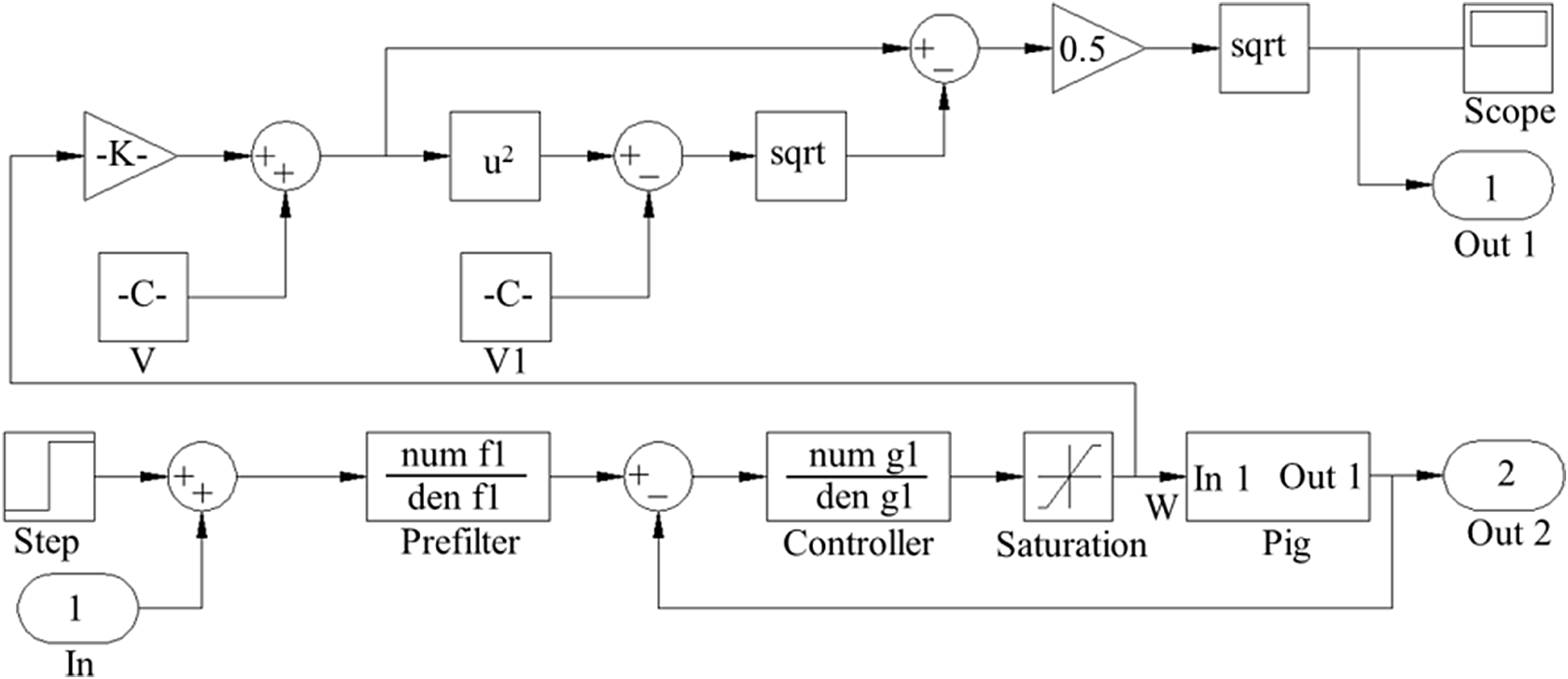
Mirshamsi and Rafeeyan [Reference Mirshamsi and Rafeeyan41] proposed a new control method called Sobhani–Rafeeyan method by using the quantitative feedback theory and the control block diagram of the robot (Fig. 45). And the controller equation is Eq. (31).
Control block diagram of the robot [Reference Mirshamsi and Rafeeyan41].

 \begin{equation} P=\frac{v_{\text{robot}}\left(s\right)}{W\left(s\right)}=\frac{v^{2}f(x)-2vf(x)^{2}\sqrt{1+f'(x)^{2}}+\left(1+f'(x)^{2}\right)f(x)^{3}}{f(x)\sqrt{1+f'(x)^{2}}s+\left(-k+\dfrac{\mu f''(x)\mathrm{sgn}(x)+f'(x)f''(x)}{1+f'(x)^{2}}f(x)^{2}\right)\sqrt{1+f'(x)^{2}}} \end{equation}
where
 $k=-\frac{5\rho L_{\text{robot}}v^{2}f(x)}{2mD\sqrt{1+f'(x)^{2}}}+\frac{4\rho gAL_{\text{robot}}f'(x)}{m\left(1+f'(x)^{2}\right)}-\frac{\mathrm{g}f'(x)}{1+f'(x)^{2}}-\frac{\mathrm{sgn}(x)\mu \mathrm{g}}{1+f'(x)^{2}}$
, P is transform function, v(s) is the output velocity, W(s) is the control input, f(x) is the centerline of the robot, v is the robot velocity, μ is the coefficient of friction,
 $\rho$
is the fluid density, A is the cross-sectional area, m is the mass of the robot, A
h is the cross-sectional area of the valve, L
robot is the length of the robot, and D is the pipe diameter.
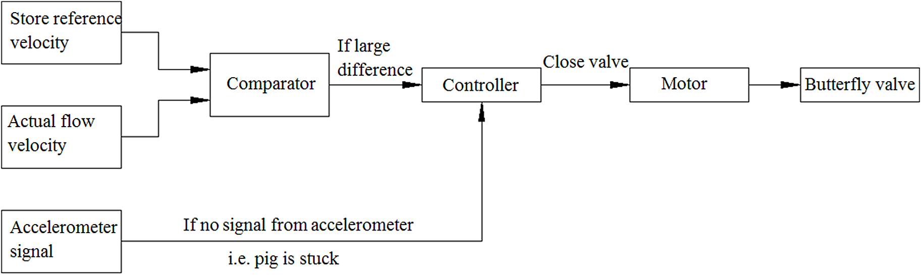
Yardi [Reference Chaitanya22] proposes a control method to prevent the robot from being stuck, as shown in Fig. 46. The control algorithm is that if the robot is detected and judged to being stuck, the robot can automatically close the bypass valve for maximizing the driving force of the robot.
The control method of keeping robot from being stuck [Reference Chaitanya22].

5. Discussion
5.1. Anti-stuck technologies for the LDPPRs
There are still some difficulties in long-distance pipeline inspection or maintenance: (1) in a long oil and gas pipeline, especially in a production pipeline, the reliability and stability of a robot are crucial. If there is a stuck accident in a production pipeline, it will lead to a serious result. (2) The matching accuracy between the location information and the inspection data will determine the time and cost of the pipeline excavation and overhaul. (3) The inspection of the outer wall of the underground pipeline is also difficult. Therefore, it is necessary to analyze the technologies of preventing stuck accident and the precise location technologies.
Kenney A [Reference Kenney64] and Bybee K [Reference Bybee65] pointed out that due to the shape of oil and gas pipelines and wax accumulation, the LDPPR has a probability of more than 50% that a stuck accident occurs, these oil and gas pipelines are called “unpiggable” pipelines. Therefore, the application and research of LDPPRs anti-stuck technology have great value and significance.
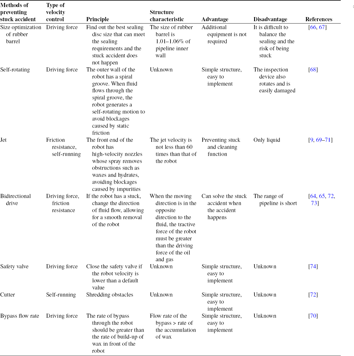
In order to keep the safety of oil and gas transportation, there are some technologies, which can prevent stuck accident, as shown in Table II.
Technologies of preventing stuck accident for LDPPR.

In a long-distance pipeline, especially in a production pipeline, the reliability and stability of a LDPPR are crucial. If there is a stuck accident in a production pipeline, the production stoppage will lead to a serious result. Therefore, the design method of the structure to prevent stuck accident is very important. Also, it is found that only one kind of anti-stuck technology is adopted in a single LDPPR, and the safety and reliability of preventing being stuck are not high. In order to minimize the risk of the stuck accident, a single robot can adopt two or more kinds of technologies to prevent stuck accident. For instance, if the probability of the failure of one type of anti-stuck technology is 10% (each anti-stuck technology is independent of each other), then the probability of the failure of two kinds of anti-stuck technologies (independent of each other) is 1%. This will greatly reduce the probability of the stuck accident and significantly improve the safety of the LDPPRs.
5.2. Inspection technology of the oil and gas pipeline
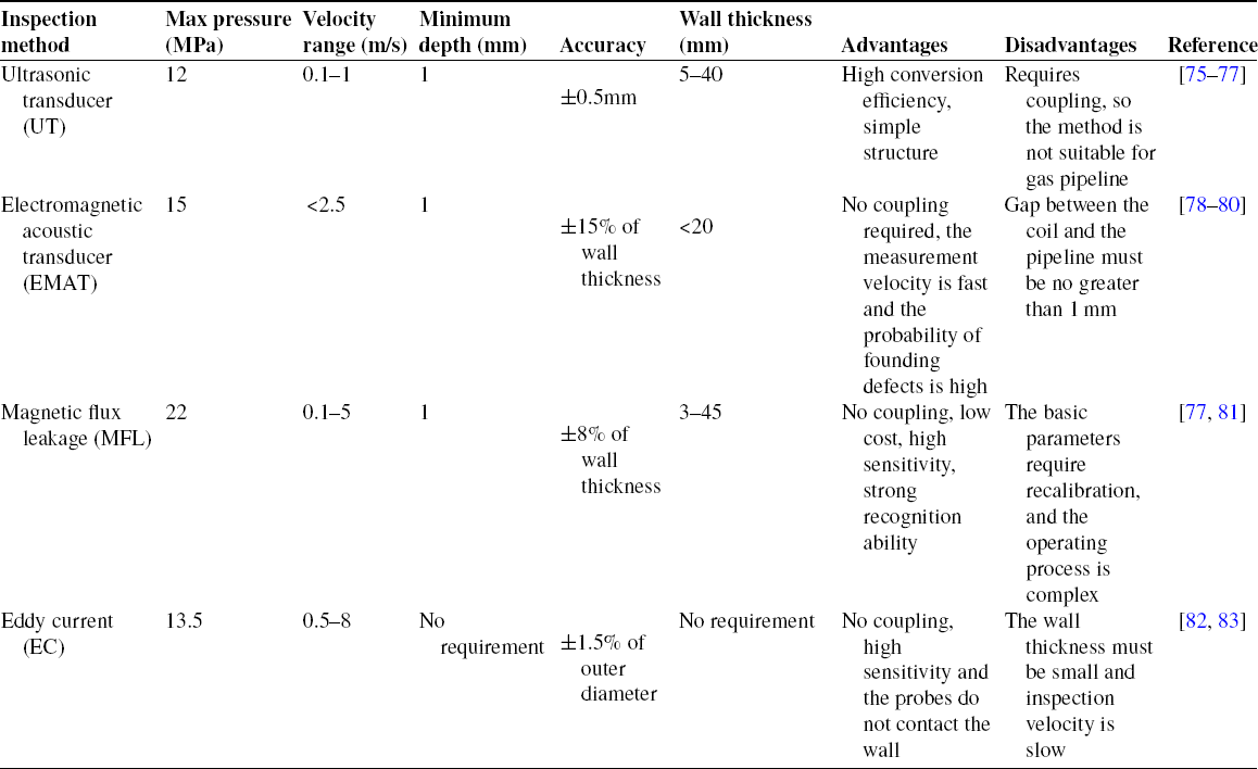
Pipeline in demanding environments is likely to be deformed or corrosion damaged. In order to improve the safety of oil and gas pipelines, the inspection and evaluation are necessary. The main inspection methods for oil and gas pipeline are shown in Table III.
Inspection technologies of a pipeline by a LDPPR.

Table 3 shows that the different inspection methods have different applicable conditions. (1) UT is not fit for the long-distance pipeline because the inspection process requires a coupling agent. However, the coupling agent cannot cover the pipe wall when the oil or gas is flowing; (2) the wall thickness of EMAT is less than 20 mm which is much smaller than that of other inspection method. Therefore, inspection methods should be optimized according to the pipe wall thickness, inspection distance, and other factors.
5.3. Location technologies in a long-distance pipeline
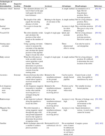
In order to repair a defective pipeline, the inspection data of a pipeline robot must match its actual position. Therefore, the real-time location function of the LDPPR is the focus in the future. Table IV shows the current location technologies in the long-distance pipeline.
Location technologies for the LDPPRs.

There is usually a large position error for the defect or stuck accident which creates a great difficulty for the late operations, such as excavation and repair. And, it is difficult to transmit the inspection data in real time (Table IV). Inaccurate and non-real time location data can create a large obstacle to find out and repair the pipe with a defect. Therefore, the current location technologies greatly reduce the efficiency of operation and increase costs. While the main reasons for the location error are
(1) Pipeline position data are produced through the iteration method. The error of a small location data is several meters, and a large location error can reach several kilometers. For example, the maximum range of the pipeline of the LDPPR of the Weatherford’s MultiCal is 720 km. Its error is approximately 2%, and the absolute error of the LDPPR is more than 10 km [Reference Mingsheng85, Reference Donghui and Lijian86].
(2) Because the oil or gas pipeline is generally made of metal and usually buried underground, the output signal of the robot is greatly attenuated. Therefore, the signal is weak. The data storage is difficult because the data are too large, and it is difficult to judge whether the pipeline robot is working properly during the inspection operation. Engineers often need to repeat the inspection operation to carry out an effective risk assessment of the pipeline. This will greatly increase the workload of the pipeline inspection.
(3) Data transmission in real time is limited to the short-distance pipeline unless the multiple signal-receiving devices are installed along the long-distance pipeline. And, this type of solution is a complicated process involving a large workload, high costs, and poor reliability. Therefore, it is meaningful to develop a real-time and accurate detection technology.
6. Conclusions and prospects
Due to their different application conditions, the LDPPRs have the distinct characteristics such as the pipeline space constraints, the surrounding gas, liquid, solid, or even two-phase or multiphase mixtures, and pressure or temperature changes. Therefore, the structural characteristics and mechanics are the key factors to affect the reliability and safety of LDPPRs. In order to make the robot run more safely and reliably, the structural characteristics and the mechanical models of the LDPPRs are studied in this paper. And, there are some conclusions and prospects are obtained:
(1) According to the structural characteristics of LDPPR, the LDPPRs are classified into the velocity-uncontrollable LDPPR and velocity-controllable LDPPR. Among them, because the robot velocity will affect the accuracy of the inspection data and the reliability of other operations, the velocity-controllable LDPPR is the focus of research, which is mainly subdivided into three types: velocity controlled by friction resistance, velocity controlled by driving force, and velocity controlled by self-running.
(2) For the mechanical model of velocity-uncontrollable LDPPRs, according to the shape of the rubber barrel, it can be subdivided into the spherical type of LDPPR and the cylindrical type of LDPPR. In this paper, the dynamic models or the dynamic equations of the spherical type of LDPPR and cylindrical type of LDPPR are deduced, and the theoretical calculation data have been tested in shorter pipelines. For the mechanical model of velocity-controllable LDPPRs, the best velocity control method can be found using the mechanical model; there are mainly two methods of velocity controlled by the brake and velocity controlled by the bypass. Since the structure difference of the LDPPRs is very large, the fluid mechanics and dynamics characteristics of the robot can be analyzed by experiment to obtain a more precise velocity control method.
(3) The dynamic models of the vibration are used to find out the principle of vibration mechanics and to calculate the natural frequency and resonance frequency of the system and provide a basis for the robot protection. Since the robot can count the welding point by judging the vibration characteristics and calculating the robot’s position information, the vibration characteristics of the LDPPR when it is passing through the welding point can be used to predict the robot’s position.
(4) The rubber barrel of the LDPPR is the most important accessory of the robot, which can directly determine whether the robot can operate normally. Due to the effect of the gravity, the lower part of the rubber barrel is easier to be worn, which can cause a failure of the seal. Therefore, the contact situation and the wear resistance of the rubber barrel become the focus of the future research.
(5) The research of the anti-stuck technologies and the accurate location technologies in real time of the LDPPRs is a trend in the future. A single robot can adopt two or more anti-stuck technologies to reduce the probability of blockage accidents and improve the security of LDPPR. At the same time, the use of real-time online positioning technology can effectively improve the positioning accuracy, which can provide great help for pipeline excavation, repair, and other operations.
(6) In the future, the LDPPR technology can be designed with a modular method for the traction, inspection, repair, welding, and other functions of pipeline maintenance, which will effectively reduce the number of types of robots and the cost of the research and development. At the same time, in pipelines, especially in long-distance pipelines, it is necessary to strengthen the transmission and processing of network signals in order to check the actions and locations of LDPPR in real time.
Acknowledgements
The authors thank all grant programs that funded this paper, all others who contributed to this paper, and the authors also sincerely thank the editors and the reviewers for their efforts in improving this paper.
Authors’ contributions
In this paper, Jianguo Zhao is mainly responsible for proposing research ideas and designing research plans, Ju Wang mainly searches for references and organizes data, Qingyou Liu and Xu Luo are mainly responsible for the analysis of research results, Xuecheng Dong is mainly responsible for the revision of the paper. Jianguo Zhao and Ju Wang wrote this paper. All authors read and approved the final manuscript.
Financial support
This work was funded by the National Natural Science Foundation of China (No. 52004232, U19A200380), the Sichuan Science and Technology Program (2021YJ0403, JG2021-624, 2021YFS0305, 22QYCX0196), and the Sichuan Provincial Key Lab of Process Equipment and Control (GK202006).
Conflicts of interest
The authors declare none.
Ethical considerations
The content of this manuscript is the original work and does not duplicate any other previously published work. This manuscript is submitted to “Robotica” only; it has not been considered, accepted for publication, or published elsewhere. All listed authors of this manuscript are aware of and agree to submit this manuscript. This manuscript does not contain abusive, defamatory, fraudulent, unlawful, defamatory, or obscene content. This manuscript strictly adheres to the Cambridge University Press Code of Publication Ethics.