NOMENCLATURE
- Re
Reynolds number
 $Re_c$
mean aerodynamic chord Reynolds number
- M
Mach number
- $C_P$
pressure coefficient
- $C_L$
lift coefficient
- $C_D$
drag coefficient
- $C_{MP}$
pitching moment coefficient
- $C_{MR}$
roll moment coefficient


Greek Symbol
- $\alpha$
angle-of-attack
- $\eta$
semi-span reference


1.0 INTRODUCTION
Unmanned Combat Aerial Vehicles (UCAVs) are believed by many to be the future of aerial strike/reconnaissance system because of their advantages over traditional crewed combat aircraft, such as a much lower risk to operator’s life, a smaller size and a reduced cost(Reference Woolvin1,Reference Woolvin2) . In the last two decades, much attention has been paid to a particular future UCAV concept, the UCAV 1303. The UCAV 1303 was originally designed by the Boeing Phantom Works and the US Airforce Lab (AFRL) in the late 1990s and scheduled to operate in the 2020 time frame(Reference Woolvin1,Reference McParlin, Bruce, Hepworth and Rae3,Reference Billman and Osbourne4) . Later, the design fell under The Technical Cooperation Program (TTCP), a joint defence-related forum between the United States, United Kingdom, Australia, New Zealand and Canada. The aircraft is a tail-less Blended Wing Body (BWB) (see Ordoukhanian and Madni(Reference Ordoukhanian and Madni5) for further details about BWB design) with a lambda wing configuration (Fig. 1). It has  $47^\circ$ leading edge sweep angle and
 $\pm 30^\circ$ trailing edge sweep. The lambda wing design can be identified from the existence of a convex trailing edge crank (wing sweep changes) near both of the wing tips and a concave trailing edge crank at the mid-semi-span(Reference McParlin, Bruce, Hepworth and Rae3). The vehicle is designed to be powered by a single un-reheated turbofan engine located on the centreline with expandable fuel tank, and it has two internal payload bays at either side of the engine(Reference Woolvin1,Reference Woolvin2) .
UCAV-1303 design plan by the Boeing Phantom Works and AFRL(Reference Billman and Osbourne6).

Initial studies and developments of the UCAV 1303 aerodynamics performance for the TTCP in the early 2000s involved many aspects, such as wind tunnel experiments(Reference McParlin, Bruce, Hepworth and Rae3,Reference Bruce7) , numerical Computational Fluid Dynamics (CFD)(Reference Zhang, Khalid and Ball8,Reference Petterson9) and Conceptual Design and Optimisation (CDO)(Reference Woolvin1,Reference Woolvin2) . These studies reveal that the UCAV 1303 is sensitive to Reynolds number. As  $Re_c$ increases, the UCAV 1303 lift coefficient
 $C_L$, drag coefficient
 $C_D$ and pitching moment coefficient
 $C_{MP}$ vary significantly with the angle-of-attack
 $\alpha$. Furthermore, the TTCP studies also show that the UCAV 1303 tends to be unstable even at low angles of attack.
Unlike standard aircraft, the UCAV 1303 design does not incorporate a vertical tail and has minimum control surfaces. Furthermore, it has a stealthy design which makes it operate at close to the limit of flight stability(Reference Chandrasekhara and McLain10,Reference Chandrasekhara, Sosebee and Medford11) . The UCAV 1303 design has been subjected to many aerodynamic control studies, both computational and experimental, such as using traditional surface control (flaps and ailerons)(Reference Chung and Ghee12,Reference Jeong, Lee, Shim, Ahn, Choi, Park and Oh13) , active flow control with synthetic jets(Reference Lee, Lee and Kim14) and even plasma actuators(Reference Patel, Ng and Vasuvedan15–Reference Nelson, Corke, He, Othman, Matsuno, Patel and Ng18). One flight control method for the UCAV 1303 that has not been discussed in great detail is the morphing wing technology. The idea of the morphing wing is inspired by nature, particularly birds and flying mammals (i.e. bats). Utilising their muscle, skeleton and feathers, birds can sweep their wings at high speed and spread their wings in turns or decelerate(Reference Lentink, Müller, Stamhuis, de Kat, van Gestel, Veldhuis, Henningsson, HedenstrÖm, Videler and van Leeuwen19). The term morphing is defined as a set of technologies that increase a vehicle’s performance by manipulating certain characteristics to better match the vehicle state to the environment and task at hand(Reference Weisshaar20,Reference Bowman, Sanders and Weisshaar21) . Such systems provide superior system capabilities, which will enable the aircraft to undertake a wide range of missions with changing parameters. The simplest parts of an aircraft to change during a flight are the wings. They can undergo changes in geometry (e.g. span, area, chord, sweep, etc.) such that the wing configuration is optimised for widely varying flight conditions (e.g. loiter, dash and high-speed manoeuvres)(Reference Bowman, Sanders, Cannon, Kudva, Joshi and Weisshaar22). This morphing wing ability has the potential to revolutionise future military and commercial aircraft.
In this report, we will conduct an investigation into several possible morphing wing methods that would result in improved manoeuvring performances and stabilities of the UCAV 1303. The investigation is conducted via CFD simulation using a commercial-based software FLUENT-ANSYS. To validate the CFD solver, we conduct a baseline model CFD simulation and compare the results with published wind tunnel data for the UCAV 1303. Following this, we investigate several morphing cases, such as a linear twist on a section of one of the outer wings of the UCAV-1303 (which allows the model to perform rolling movement), and twists at both wings which force the flow to remain attached at a high angle-of-attack  $\alpha$ (wash-in and washout). The linear twist on one of the wings is compared with a more traditional surface control such as elevons.
2.0 NUMERICAL METHOD
In this study, we use FLUENT software package by Ansys, with incompressible Reynolds Averaged Navier–Stokes (RANS) solver and turbulence model  $k-\omega$ SST (Shear Stress Transport). We chose this turbulent model based on the report by Wong et al.(Reference Wong, McKenzie, Ol, Petterson and Zhang23) and Arthur and Petterson(Reference Arthur and Petterson24) where it was found that
 $k-\omega$ SST turbulent model can resolve the near-wall flow relatively well (see Monk and Chadwick(Reference Monk and Chadwick25) for comparison of various turbulence model simulations on UCAV-1303). We also choose incompressible flow because the simulation is run at a low Mach number (0.25 Mach). The freestream turbulence intensity value is set at 5% with turbulent viscosity ratio of 0.01. Note that these values were chosen arbitrarily because of the lack of information in the corresponding experimental data. We have tested several different turbulence intensity values; however, we found no significant differences in the final results.
The meshing in this study is constructed using ANSYS ICEM CFD package via unstructured tetrahedral mesh, generated by the Delaunay triangulation method, to best capture the UCAV 1303 complex geometry and resolve the sharp edge at the wing tip(Reference Tournois, Wormser, Alliez and Desbrun26,Reference Si27) . The mesh is set to have five prism layers over the fuselage and wings of the UCAV-1303 model. Here we set the prism growth rate as 1.3, and the layer thickness was selected to cover  $30<y^+<300$ (where
 $y^+ = U_\tau y/\nu$, y is the wall normal distance,
 $U_\tau$ is skin friction velocity and
 $\nu$ is kinematic velocity). Note that the majority of the cells are in the range of
 $30<y^+ < 100$, where most of the turbulence energy resides(Reference Hutchins and Marusic28,Reference Hutchins and Marusic29) . To ensure that our mesh is proper, several different mesh qualities were investigated (including different mesh settings and numbers). The mesh arrangements which produced results that are mostly independent of different mesh settings, whilst keeping the total mesh number minimal, are selected as the final mesh.
The UCAV 1303 model mesh is placed in the centre of a full sphere with a radius of  $\approx 10$ root chords. This length provides sufficient distance to prevent any boundary interactions. Furthermore, the spherical shape allows for a single mesh to be used over multiple angles of attack
 $\alpha$, via changes in the boundary condition. Various initial studies by the TTCP show that the UCAV 1303 is sensitive to sharp edges, i.e. in the leading edge and wing tip(Reference McParlin, Bruce, Hepworth and Rae3,Reference Bruce7) . To overcome this issue, we generated a finer mesh at these locations. In this study, we use either half or the entire UCAV 1303 model. The half model is used when there are no differences between the port side and the starboard side of the UCAV 1303, i.e. baseline case or when both wings are morphed. This half model would allow us to use less computational resources. However, for a case where one of the wings is modified, we use the full model. This attention to detail resulted in a mesh with approximately 1.7 million cells for the half-model baseline body simulation and 3.4 million cells for the full model simulation. In this study, we use Fig. 2 as the wing semi-span reference locations.
Semi-span details (taken from Ref. (Reference McParlin, Bruce, Hepworth and Rae3)).

3.0 MODEL VALIDATION AND BASE CASE
To ensure that our simulation is valid, we conduct a baseline simulation model to match the experimental data from Bruce and Mundell(Reference Bruce and Mundell30) and McParlin et al.(Reference McParlin, Bruce, Hepworth and Rae3). Here, the baseline simulation is conducted at a Mach number of 0.25 with Reynolds number of  $5.6 \times 10^6$ based on the mean aerodynamic chord (the simulated model has a similar dimension as the experiment model). The simulation was conducted at angles of attack
 $\alpha =$
 $ 0^{\circ}, 5^{\circ}, 7^{\circ}, 8^{\circ}, 9^{\circ}, 10^{\circ}, 12.5^{\circ}, 15^{\circ}$. We did not go beyond
 $\alpha > 15^\circ$, because we assume such an angle would exceed the onset of the unstable condition, and it is outside the scope of this study. Figure 3 shows a comparison between the experiment data (black solid square)(Reference McParlin, Bruce, Hepworth and Rae3,Reference Bruce and Mundell30) and the CFD (black open circle) results from the current study, where (a) is coefficient of lift versus angle-of-attack, (b) coefficient of drag versus angle-of-attack, (c) pitching moment coefficient versus angle-of-attack and (d) ratio of coefficient of lift and drag versus angle-of-attack.
The coefficient of lift from the CFD results agrees well with the experimental data, while the coefficient of drag from the numerical simulations show slightly higher values than that of the experiments (although the curve is similar). The wind tunnel experiment that was conducted by Bruce and Mundell(Reference Bruce and Mundell30) and McParlin et al.(Reference McParlin, Bruce, Hepworth and Rae3) involves a large sting cylinder attached to the rear of the UCAV 1303 model for support. We believe that this discrepancy is due to the absence of the sting support (which would affect the flow field) on the rear of our simulation. The slightly higher  $C_D$ numerical simulation translates to a lower ratio of coefficient of lift and drag at
 $0^\circ < \alpha <12.5^\circ$ (Fig. 3(d)). The pitching moment coefficient from the CFD shows good agreement with the experiment data at
 $\alpha < 10^\circ$. Beyond this angle-of-attack, the
 $C_{MP}$ deviates slightly compared with the experimental data. Although the
 $C_{MP}$ from our CFD slightly deviates, it exhibits a higher accuracy compared to that of the TTCP CFD simulations (see Wong et al.(Reference Wong, McKenzie, Ol, Petterson and Zhang23) for the TTCP CFD results). The UCAV 1303 tends to experience pitch break at
 $\alpha \approx 8^\circ - 9^\circ$. This behaviour has been well documented for UCAV 1303, and it is caused by the large-scale leading-edge vortices that grow and move further from the fuselage centreline towards the outer edge of the wings.
Matching experiment (closed black square) and CFD (open black circles) data with (a)  $\textit{C}_{\textit{L}}$, (b)
 $\textit{C}_{\textit{D}}$, (c)
 $\textit{C}_{\textit{MP}}$ and (d)
 $\textit{C}_{\textit{L}}/{\textit{C}}_{\textit{D}}$. Experiment data are taken from Refs. (Reference McParlin, Bruce, Hepworth and Rae3,Reference Bruce and Mundell30):
 $\textit{Re}_{\textit{c}}\ \text{=}\ \text{5.6}\,\mathit{\times}\,\text{10}^{\text{6}} $ (black
 $\blacksquare$). CFD data from current study at
 $\textit{Re}_{\textit{c}}\ \text{=}\ \text{5.6}\,\mathit{\times}\,\text{10}^{\text{6}}$ (black open
 $\circ$).

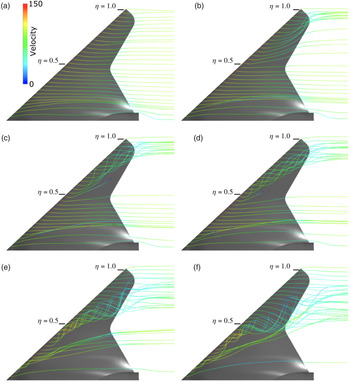
Figure 4 shows the flow visualisation of the streamlines from above the leading edge. At a low angle-of-attack ( $\alpha \le 5^\circ$), there is no flow separation. At
 $\alpha = 7^\circ$, the flows on the trailing edge of section
 $\eta = 0.6 - 0.8$ (Fig. 2) tend to move towards the outer edge of the wing. At higher angle-of-attacks (
 $\alpha = 8^\circ$ and
 $9^\circ$), large-scale helical structures formed at
 $\eta \approx 0.5$, and these vortices also move towards the outer edge of the wing (trailing edge of
 $\eta \approx 0.8$ to
 $1.0$). As the
 $\alpha$ is increased further towards
 $12.5^\circ$ and
 $15^\circ$, the source of the vortical motion moves further towards the nose tip of the UCAV 1303 and becomes larger in size. Interestingly, these large vortical structures that leave the trailing edge move closer to the centre line of the UCAV-1303 (trailing edge of
 $\eta \approx 0.5$ to
 $0.6$). These large vortical structures and unique flows are also recorded on the oil film experiment by McParlin et al.(Reference McParlin, Bruce, Hepworth and Rae3), and they are believed to be the cause of instability of the UCAV 1303 at a high angle-of-attack, i.e. at
 $\alpha>10^\circ$. The CFD of the baseline UCAV 1303 model in this study closely matched the experimental data. Hence, it provides confidence to extend the study further and to conduct wing profile modifications as discussed in the following sections.
Set of 30 streamlines released from a rake a short distance above the leading edge of wing, coloured by velocity, for selected angles of attack: (a)  $\mathit{\alpha}\ \text{=}\ \text{5}^{\circ}$, (b)
 $\mathit{\alpha}\ \text{=}\ \text{7}^{\circ}$, (c)
 $\mathit{\alpha}\ \text{=}\ \text{8}^{\circ}$, (d)
 $\mathit{\alpha}\ \text{=}\ \text{9}^{\circ}$, (e)
 $\mathit{\alpha}\ \text{=}\ \text{12.5}^{\circ}$, (f)
 $\mathit{\alpha}\ \text{=}\ \text{15}^{\mathit{\circ}}$

4.0 GEOMETRIC MODIFICATIONS
For this study, we will investigate the geometric modifications in the form of elevons as a traditional surface control, as well as two cases of morphing wings, i.e. linear twists on one of the wings and linear twists at both wings (wash-in and washout). Here, the meshing and the computational solver settings are set to mimic the baseline studies in the previous section. One main difference is that, for the elevons and linear twist cases, the simulation will be conducted on full models, doubling the total mesh size. In the case of linear twist at both wings (wash-in and washout), the simulation is conducted at half body, because of the symmetry and to save computational power. The geometric modifications are conducted via a modification of the geometry portion of the save file from ICEM-CFD using a custom MATLAB script. The modified geometry and morphing are then checked for errors using ICEM-CFD, and finally, a three-dimensional (3D) mesh can be produced over the new geometry file. Note that we acknowledge that there are many other possible geometry modifications, such as using rounded leading edge to improve the coefficient of moment. However, in this report we having chosen to focus on the wing twisting because we are also interested to investigate how well it can generate a rolling moment.
4.1 Elevons as surface control
In this section, we will examine the aerodynamic effects of traditional elevons as a surface flow control. This analysis would allow us to compare the roll moments from the morphing wing cases, which will be presented in later sections. Figure 5 shows the locations of the elevons, and it is overlaid with the coefficient of pressure  $C_P$ contours at an angle-of-attack of
 $7^\circ$. The elevons are located at the outer wing section of the UCAV 1303 to generate maximum roll moments. The elevons are modelled by twisting the wing in an upward or downward direction at
 $5^\circ$. Note that this angle was chosen arbitrarily, and it was considered sufficient for a velocity of Mach 0.25 (the flight envelope of the simulation and wind tunnel testing). The CFD simulations were conducted at angle-of-attacks
 $\alpha = 5^\circ$,
 $7^\circ$,
 $8^\circ$ and
 $9^\circ$. These angles are chosen as the appropriate representation where the UCAV 1303 is likely to operate before the onset of pitch break/instability (Fig. 3(c)).
UCAV 1303 with the elevons location, coefficient of pressure  $\textit{C}_{\textit{P}}$ contours at an angle-of-attack of
 $\text{7}^\circ$. The left-hand images show underside, and the right-hand side shows top surface of the UCAV 1303.

Figure 6 shows the aerodynamic properties of UCAV 1303 with elevons, i.e. (a) coefficients of lift, (b) coefficient of drag, (c) coefficient of pitching moment, (d) coefficient of rolling moment and (e) ratio between coefficient of lift and drag. The coefficient of lift and drag plots show that there are not many differences between the baseline case and the elevon case (apart from the  $C_D$ at
 $5^\circ$). The almost identical coefficients of lift
 $C_L$ and coefficients of drag
 $C_D$ values are probably due to the location of the elevons (which is on the trailing edge, and contributes little to the lift generated), and their directions are anti-symmetrical (one is upward and the other is downward). The ratio of
 $C_L$ to
 $C_D$ (Fig. 6(e)) shows that, in general, the baseline UCAV 1303 model has a slightly higher ratio than that of the model with elevons. Having elevons on the wings would result in a variation for the coefficients of pitching moment
 $C_{MP}$ (Fig. 6(c)), particularly at
 $\alpha \approx 8^\circ$, where the UCAV 1303 model tends to experience pitch break. The plot shows an increase in
 $C_{MP}$ at this particular
 $\alpha$ compared with the baseline case. We suspect that the elevation in
 $C_{MP}$ at low
 $\alpha$ is due to the increase of lift near the trailing edge of the wing (due to elevon), which would result in a nose-down pitch coefficient of moment.
(a)  $\textit{C}_{\textit{L}}$, (b)
 $\textit{C}_{\textit{D}}$, (c)
 $\textit{C}_{\textit{MP}}$ and (d)
 $\textit{C}_{\textit{MR}}$, (e)
 $\textit{L}/\textit{D}$ for the elevons as flow control against the baseline case. Solid lines with open circle represents the baseline case, and the dashed line with open triangles represents the elevon case.

Finally, the elevons generate a roll mode tendency that can be observed in the coefficients of rolling moment  $C_{MR}$ plot (Fig. 6(d)). The geometry variation due to the elevon on one of the wings causes a change in the pressure difference between the top and lower part of the wing, resulting in a tendency to roll. The coefficients of rolling moment decrease with the angle-of-attack, which is probably due to the elevon’s location (at the trailing edge). As
 $\alpha$ increases, the leading edge vortices that are generated by the UCAV 1303 become stronger and larger (Fig. 4). This would cause the flow around the trailing edge to be entrained into the recirculation region behind the large-scale leading-edge vortices, resulting in a reduced
 $C_{MR}$.
4.2 Morphing wing case 1: linear twists
The first morphing case that we investigate is a linear twist. The linear twist aims to reduce the wing’s local angle-of-attack while it generates a rolling moment and delays pitch break simultaneously. The morphed wing is designed to delay the onset of pitch break by lowering the wing’s effective angle-of-attack, particularly over the area where the pitch break occurs. Thus it would allow the wing to maintain an attached leading-edge vortex. Here the linear twist is applied at the outer third of the wing ( $\eta > 0.7$), which results in a gradual twist configuration along the axis of interest (Fig. 7). Here only one of the wings is twisted (port side). For this study, we conducted two linear twist cases:
 $10^\circ$ and
 $30^\circ$. Note that the twist angles are referred to as the total twist at the wing tip; therefore, for a
 $30^\circ$ linear twist angle, at an angle-of-attack of
 $5^\circ$, the wing tip would have an effective angle-of-attack of
 $ 5^\circ - 30^\circ = -25^\circ$. Note that we did not conduct a morphing wing twist at
 $5^\circ$ on one of the wings, which would have matched the elevon’s angle. This is because one of the main aims of this investigation is to eliminate or delay pitch break; a low wing-twist angle such as
 $5^\circ$ is not as effective as higher twist angles.
Illustration of UCAV 1303 with a  $\text{30}^\circ$ linear twist applied to one of the wings about the red-line axis.

Figure 8 shows the aerodynamic characteristics of UCAV 1303 when it undergoes a linear twist at angles  $10^\circ$ (dashed lines with cross sign) and
 $30^\circ$ (dashed lines with plus sign), the elevon case (dashed line with open triangles), and the baseline case (solid lines with open circles). Figure 8(a) illustrates the coefficient of lift
 $C_L$ at various angles of attacks
 $\alpha$; here the plot shows a vertical downward shift with increased linear twist angles. The reduced
 $C_L$ is due to the change in the effective angle-of-attack due to twisting. The coefficient of drag
 $C_D$ in Fig. 8(b) shows that, at a low angle-of-attack (
 $\alpha = 0^\circ - 5^\circ$), the twisted wing cases show a higher
 $C_D$ than that of the baseline case. The higher
 $C_D$ may be due to the increased wing twisting that causes the model to behave more like a bluff body. At a higher angle-of-attack (
 $\alpha = 7^\circ - 15^\circ$), however, the
 $C_D$ is lower because the twisted wings effective angle-of-attack was closer to
 $0^\circ$, resulting in a more streamlined wing fuselage. Note that, even with the lower drag
 $C_D$, the maximum
 $C_L/C_D$ of the twisted wings, at
 $\alpha = 5^\circ$, is still lower than that of the baseline case (Fig. 8(e)). At a higher angle-of-attack (
 $\alpha > 7^\circ$), the
 $C_L/C_D$ ratio of the twisted wing cases show slight improvement compared with the baseline cases. The elevon case, on the other hand, has almost negligible influences on the
 $C_D$ and
 $C_L$, as we have shown in the previous section.
(a)  $\textit{C}_{\textit{L}}$, (b)
 $\textit{C}_{\textit{D}}$, (c)
 $\textit{C}_{\textit{MP}}$ and (d)
 $\textit{C}_{\textit{MR}}$, (e)
 $\textit{L}/\textit{D}$ for various linear twists. Solid lines with open circle represents the baseline case, dashed lines with cross sign the
 $\text{10}^\circ$ linear twist case, dashed lines with plus sign the
 $\text{30}^\circ$ linear twist case and dashed line with open triangles the elevon case.

The coefficients of pitching moment  $C_{MP}$ due to linear twist are illustrated in Fig. 8(c). From the plot, It is clear that linear twisting does not prevent the onset of pitch break. The UCAV 1303 still experiences pitch break at
 $\alpha \approx 8^\circ - 9^\circ$. However, it is clear that the difference in
 $C_{MP}$ magnitude between the lower
 $\alpha$ (
 $\alpha<8^\circ$) and higher alpha (
 $\alpha > 8^\circ$) for the twisted wing cases are smaller than that of the baseline cases;in other words, the
 $C_{MP}$ profiles on the twisted wing cases at low
 $\alpha$ are shifted up when compared with the baseline case. Hence, twisting the UCAV 1303 wing influences
 $C_{MP}$, and reduces the difference in
 $C_{MP}$ magnitude with respect to
 $\alpha$. At very high angle-of-attack,
 $\alpha > 13$, the pitching moment coefficients of the twisted wing have a tendency to merge into the baseline case. It seems that this is due to the large-scale leading-edge vortical structures that are formed closer to the nose tip and leave the trailing edge closer to the UCAV-1303 centreline. Referring back to Fig. 4(e) and (f), the majority of the large-scale leading-edge vortical flows at a high angle-of-attack (
 $\alpha > 12.5^\circ$) leave the wing at trailing edge location of
 $\eta \approx 0.5$, near the rear concavity. Furthermore, note that the linear twisting happens at the outer third of the wing (
 $\eta > 0.7$). Therefore, the twisting has an only partial or small influence on the large-scale vortical structures, which in turn results in small change in
 $C_{MP}$ at high
 $\alpha$. Note that the
 $C_{MP}$ vertical shifting of the twisted wing cases (Fig. 8(c)) is much more aggressive than in the case of the elevon, because the twist angle (
 $10^\circ$ and
 $30^\circ$) is higher than the elevon angle (
 $5^\circ$). We did not conduct elevon simulation at a higher angle because of the small influence on the models coefficients of pitching moment. In these cases, there is only one wing that is twisted; hence, although the twisted wings may influence (or possibly reduce) the pitch break, the other wing side would still experience pitch break.
Location of linear wing twist for the  $\mathit{\pm} \text{5}^\circ$ washout and wash-in cases.

Figure 8(d) shows the coefficients of rolling moment  $C_{MR}$ for both the
 $10^\circ$ and
 $30^\circ$ twisted wings. Here we also include the elevon case as a comparison. Note that for the baseline case, there are no changes in
 $C_{MR}$, as it is zero. For both twisted wing cases, we can see that there is a variation of
 $C_{MR}$, albeit it is fairly steady at
 $\alpha$. The variation in the coefficients of rolling moment is due to the twisting of one of the wings, which results in a rolling tendency for the UCAV 1303 model. Here we can see that the
 $30^\circ$ twist case generates a much larger
 $C_{MR}$ (
 $\approx 3\times$) than that of the
 $10^\circ$. The higher twist angle would translate into a higher pressure difference between the top and lower part of the wing, resulting in a higher roll tendency. The elevon
 $5^\circ$ case seems to have higher coefficients of roll moment than that of the
 $10^\circ$ twisted wing, particularly at a lower angle-of-attack (
 $\alpha < 8^\circ$).
4.3 Morphing wing case 2: wash-in and washout
In the previous section, we have shown that the linear twist cases are not able to prevent or delay the onset of pitch break, although the magnitude is reduced. This condition is probably due to the pitch break forming very near to the wing tip; hence, it is not delayed significantly by the wing twist. To test this hypothesis, a less aggressive linear twists ( $5^\circ$) is applied at both wing ends over a larger area of the wing, starting from the concavity of the trailing edge at
 $\eta = 0.5$ (Fig. 9). As a comparison, the previous linear twist cases (where only one side of the wing twisted) occur at
 $\eta = 0.6$. The twisting of both wings would result in them behaving more like traditional washout and wash-in configurations. Washout can be defined as “inbuilt wing twist resulting in an angle of incidence reducing towards tips” (Reference Gunston31), while wash-in is the opposite, where the angle of incidence is increasing towards the wing tip. Figure 10 illustrates the definition of washout for further clarification(Reference Phillips32). Note that some of the initial results from this section have been reported by Brett et al. (2010)(Reference Brett, Tang, Hutchins and Ooi33).
Illustration of washout (taken from Ref. (Reference Phillips32)).

(a)  $\textit{C}_{\textit{L}}$, (b)
 $\textit{C}_{\textit{D}}$, (c)
 $\textit{C}_{\textit{MP}}$ and (d)
 $\textit{C}_{\textit{MR}}$, (e)
 $\textit{L}/\textit{D}$ for wash-in and washout. Solid lines with open circle represent the baseline case, dashed lines with diamond markers the washout case and dashed lines with pentagram markers the wash-in case.

Figure 11 shows the aerodynamic coefficients for the baseline case (solid lines with open circles), washout case (dashed lines with diamond markers) and wash-in case (dashed lines with pentagram markers). The coefficient of lift and drag plots in Fig. 11(a) and (b) shows that the washout case has a lower coefficient than that of the baseline case, while the wash-in case has a higher coefficient than the baseline case. The lower coefficient of lift  $C_L$ of the washout case is similar to that of linear twist from one of the wings in the previous section. The reduced
 $C_L$ is caused by the reduced effective surface area of the wings (due to the twisting). Hence, the higher the washout angle, the lower the lift coefficient will be (when it is compared with the baseline case). On the other hand, the wash-in configuration would allow the wing to have a greater surface area, resulting in an increased lift coefficient. With regard to the coefficient of drag, the washout case has a lower coefficient of drag
 $C_D$ compared with the regular wings because of the twisted wing angle forces the wings effective angle-of-attack closer to
 $0^\circ$. This would result in a more streamlined UCAV-1303 at higher
 $\alpha$, i.e. the
 $C_D$ profile shifts to the right. For the wash-in case, however, the effective angle-of-attack of the wing would always be higher than that of its intended
 $\alpha$. A higher effective angle-of-attack would result in a
 $C_D$ increase higher than the base model, i.e. the coefficient of drag is shifted to the left. Interestingly, however, when we account for the
 $C_L/C_D$ ratio (Fig. 11(d)), the washout case shows a better ratio than the wash-in case. The
 $C_L/C_D$ ratio is higher than the baseline case, suggesting that the washout case has better aerodynamic performance than the wash-in case. The improved
 $C_L$ from the wash-in case raises questions regarding how it would fare with the other flow control methods. A popular flow control technique that is often applied to UCAV 1303 is plasma actuators(Reference Patel, Ng and Vasuvedan15-Reference Nelson, Corke, He, Othman, Matsuno, Patel and Ng18). When compared with the plasma actuator technique, our
 $C_L$ performs better, i.e. when it is compared with the baseline case, the
 $C_L$ from our wash-in case is higher than the plasma actuator technique. However, the
 $C_D$ result is not as good as the plasma actuator method. The
 $C_D$ from wash-in is higher than the baseline case, while the plasma actuator method gives lower
 $C_D$.
The pitching moment coefficient figure (Fig. 11(c)) shows that the washout case shifts the  $C_{MP}$ values upwards when it is compared with the baseline case, particularly at
 $\alpha < 12.5^\circ$. Beyond this angle, it seems that the washout has little effect on the pitching moment coefficient (similar to the one-wing linear twist in the previous section). The similar behaviour of the washout
 $C_{MP}$ and baseline case
 $C_{MP}$ at
 $\alpha$ beyond
 $12.5^\circ$ is due to the location where the large-scale leading-edge vortices leave the wing trailing edge. Figure 4(e) and (f) have shown that, at
 $\alpha > 12.5^\circ$, the large-scale leading-edge vortices leave the wing trailing edge at
 $\eta \approx 0.5$, near the concavity, while the twisting happens at the outer third of the wing (
 $\eta > 0.7$). Hence, the washout twist has a small influence on the large vortical structures on the trailing edge. The wash-in case, on the contrary, shows that it generates a reduced
 $C_{MP}$ with
 $\alpha$, relative to the baseline case. Both wash-in and washout cases show that they do not significantly modify the onset of pitch break (which is around
 $\alpha \approx 8^\circ - 9^\circ$). This may indicate that the twisting effect is too weak or the leading edge vortices detach further upstream before the twisting location. Although the wash-in and washout are unable to prevent pitch break or change the onset of pitch break, they may be useful for flight control purposes, for example, as a temporary shift in pitching moment that would lead to the increase or decrease of aircraft pitch angle.
Figure 12 shows the contours of the coefficient of pressure  $C_P$ and wall shear lines, for the (a) baseline case, (b) washout case and (c) wash-in case, at
 $\alpha = 10^\circ$. This angle-of-attack is chosen because it is slightly after the onset of pitch break. The washout wall shear lines have a similar flow pattern to the baseline case. Here, the pressure at the leading edge of the washout case is low at
 $\eta \approx 0.5$ and after the concavity in the trailing edge where the twist begins. Furthermore, the pressure remains weaker over the outer wing
 $\eta \approx 1.0$, which would account to the loss in lift and an increase in pitching moment.
Contours of coefficient of pressure  $\textit{C}_{\textit{P}}$ and wall shear lines, for the (a) baseline case, (b) washout case and (c) wash-in case, at
 $\mathit{\alpha}\ \text{=}\ \text{10}^\circ$.

The wash-in case has a unique effect on the airflow; here the pressure is low at  $\eta \approx 0.5$, but the pressure remains strong as the vortex travels down the wing until the point of vortex detachment at the outer wing
 $\eta \approx 1.0$. Such results come from the combination of upwards twist (increasing
 $C_P$) and bringing the wing upward towards the vortex slightly. Interestingly, both of these cases of geometry morphing do not appear to have a significant effect on the detachment location of the leading-edge vortex.
5.0 CONCLUSION
In this report, we have conducted several CFD simulations on UCAV 1303, which include baseline model and various wing geometric modifications. The baseline simulation results have good agreement with the experimental data in the literature, particularly for the  $C_D$,
 $C_L$ and
 $C_{MP}$. The baseline simulation results provided confidence to conduct further studies on wing profile geometric modifications. A geometric modification in the form of elevon and linear twist morphing (
 $10^\circ$ and
 $30^\circ$) was conducted on one of the UCAV 1303 wings. The aim of the linear twist is to produce rolling moment and to delay pitch break simultaneously. The coefficient of rolling moment
 $C_{MR}$ from the linear twist is relatively small, independent of the angle-of-attack
 $\alpha$, and has a magnitude comparable to the elevon results. The higher linear twist angle (
 $30^\circ$) generates a larger
 $C_{MP}$ magnitude, approximately three times larger than the
 $10^\circ$ twist case. The large coefficient of pitching moment may prove to be useful for manoeuvring capabilities and can offer improvements in several other areas, i.e. stealth or reliability.
The wash-in and washout morphing geometry shows that it has a significant influence on the coefficient of lift, coefficient of drag and the pitching moment coefficient over a wide range of  $\alpha$. The washout case seems to be more promising because of its ability to generate an improvement of the
 $C_L/C_D$ ratio over the entire angle-of-attack envelope. If we assume that the UCAV 1303 is properly trimmed to fly steadily at the desired
 $\alpha$, a temporary morph such as wash-in and washout would produce a rapid desirable change in its flying characteristics. In short, the morphing wing has plenty of potential for future UCAV, such as UCAV 1303. Further investigation into a more aggressive or sophisticated morphing geometry is needed to extract the full potential of such capability. Note that for real morphing wing applications, a vast possibility of potential geometries exists. Since morphing occurs over a finite time duration, in addition to studying the geometries, the transient influence of the morphing wing is another aspect that can be studied.