Introduction
Today, wireless communication systems with high data rates have received a lot of attention [Reference Khajeh-Khalili, Honarvar, Dadgarpour, Virdee and Denidni1]. On the other hand, the construction of small-scale communication equipment has always been a major goal for researchers. For this purpose, the microstrip antennas are a good option [Reference Kishk2]. But these antennas also have limitations such as the narrow bandwidth and low gain [Reference Kishk2]. This will be even more important when antennas are used for high-precision systems such as medical systems. In this case, a wide bandwidth is an essential requirement. In addition, antennas designed for wearable applications must be flexible. However, conventional dielectrics used in the design of microstrip antennas are hard and inflexible. So overall, wearability, wide bandwidth, and the suitable gain are the most important challenges we face in designing antennas that can be used in medical/communication systems. But the hopeful point is that in this paper, all of the above challenges have been investigated and, to a large extent, the issues raised have been addressed.
In recent years, to increase the wearable and planar antenna bandwidth, methods such as using periodic structures such as electromagnetic bandgap (EBG) [Reference Ashyap, Dahlan, Abidin, Dahri, Majid, Kamarudin, Yee, Jamaluddin, Alomainy and Abbasi3] and the help of multi resonators close to each other [Reference Chopra and Kumar4] are among the most famous technologies. In order to increase the antenna's gain, the use of parasitic elements [Reference Hussain, Tran and Le5], the employment of metamaterial and periodic structures [Reference Nguyen and Vu6–Reference Khajeh-Khalili, Honarvar, Naser-Moghadasi and Dolatshahi8] are common. For example, authors in [Reference Khajeh-Khalili, Honarvar, Naser-Moghadasi and Dolatshahi8] have improved the gain of a microstrip antenna at 40 GHz, equal to 11.5 dB. But all of the above methods, despite all their advantages, in addition to the complexity and increasing the cost of manufacturing, are not suitable for medical and wearable applications.
Recently, with flexible substrates, a limited number of antennas and components have been introduced so far [Reference Moradi, Fernández-García and Gil9–Reference Khajeh-Khalili, Khoubneshan and Khanjari19]. For example, in [Reference Moradi, Fernández-García and Gil9], a wearable dipole antenna at 325 MHz with the felt dielectric is presented. But the radiation efficiency is just 49%. In [Reference Karimiyan-Mohammadabadi, Dorostkar, Shokuohi, Shanbeh and Torkan10], a textile antenna with an innovative ground plane is designed for ultra-wideband (UWB) applications. The average gain and radiation efficiency in all bands are 5 dB and 60%, respectively. In [Reference El Gharbi, Martinez-Estrada, Fernández-García, Ahyoud and Gil11], a wearable antenna is designed and fabricated using felt dielectric for UWB applications (3.1–10.6 GHz). Although this antenna has good performance, the average radiation efficiency in the band is approximately 60%. Another problem of this work is the very low gain at frequencies below 5 GHz. For example, at 4 GHz, the measured gain is equal to −1.9 dB. In [Reference Mustafa and Rajendran12], a single-band multilayer wearable antenna with the help of EBG structures has been presented at 2.45 GHz. The maximum gain of this antenna is equal to 6.16 dB at 2.45. Although this antenna is wearable, multilayer design is among the notable problem of this design. Very recently, in [Reference El Atrash, Abdalgalil, Mahmoud, Abdalla and Zahran13], a single-band wearable antenna for medical application is presented. Despite all the advantages of this antenna, such as its suitable gain and the use of lightweight and low-cost fibers, its bandwidth is limited (2.4–2.5 GHz). With a little thought in the above investigations which examines the previous works, it can be easily concluded that the goal of the researchers is just to make the wearable components. However, in particular, it has not yet been considered to improve other components' characteristics in addition to being wearable. In general, research and activities have not been carried out to improve wearable antennas' performance. At the same time, our idea is to achieve simultaneous wearability and improve the performance of planar antennas. Note that a major part of the needs of modern medicine is the accurate and uninterrupted transmission of vital signs, physical condition, and other patient information. This information can easily be exchanged between the patient and the physician by the antennas in the standard wireless frequency bands. The wearability of the antenna is a necessary condition for achieving this goal. For example, the realization of the Bluetooth frequency band by the antenna can transmit a large amount of information between physicians and patients.
In this paper, a high-gain wearable dual-band antenna is designed, simulated, and manufactured. The dielectric used in this antenna is made of a standard felt with dielectric constant equal to ɛr = 1.3. The frequency ranges covered by this antenna are 1.7–2.5 and 5.4–5.95 GHz for application in several communication systems such as DCS (1.71–1.85 GHz), PCS (1.85–1.99 GHz), UMTS (1.92–2.17 GHz), Wibro (2.3–2.39 GHz), WLAN + Bluetooth + ISM (2.4–2.5 GHz), HIPERLAN2 (5.47–5.725 GHz), and WLAN (5.725–5.825 GHz). To increase the gain and bandwidth, the innovative triple transmission lines (TTLs) method was proposed, which was used in [Reference Khajeh-Khalili and Honarvar20] by the authors to increase the bandwidth of a Wilkinson power divider. Using this method, the frequency range of 5.4–5.95 GHz is obtained. Also, the gain at frequencies 2 and 5.8 GHz is equal to 8.26 and 9.86 dB, respectively. The antenna's gain at 2 GHz has improved by more than 4 dB compared to the conventional antenna. The dimensions of the proposed antenna are 80 × 92 × 2 mm3 or 0.57 × 0.67 × 0.01 λg 3, where λg is the guide wavelength at the center frequency of 2 GHz. Finally, the proposed antenna was manufactured to prove the simulations. The results of measurement and simulation are well proportioned.
Antenna design and justifications
Figure 1 shows the configuration of the proposed wearable high-gain dual-band antenna. The proposed antenna includes a conventional end-fire dipole antenna based on [Reference Khajeh-Khalili, Honarvar, Naser-Moghadasi and Dolatshahi8], a 50 Ω feed line, and the proposed TTLs structure. In the lower layer, the ground of the structure, along with the TTLs, is located to form a dipole antenna. How to determine the distance between the parallel lines of the TLLs structure is obtained by the particle swarm optimization algorithm and the calculations performed in [Reference Khajeh-Khalili and Honarvar20] by the author. Of course, for better justification, a parametric study will be reported at the end of this section. The standard felt used has a dielectric constant equal to 1.3 and a thickness of 2 mm. It should be noted that all simulations are performed by CST Microwave Studio 2019 software. In addition to increasing bandwidth and creating the second frequency band, TTLs structures have also been used to increase the antenna's gain. The final dimensions of the proposed antenna are 80 × 92 × 2 mm3 or 0.57 × 0.67 × 0.01 λg 3, where λg is the guide wavelength at the center frequency of 2 GHz. All dimensions specified in Fig. 1 are: W = 80, L = 92, W 1 = 3.5, L 1 = 29, a = 28.7, b = 4, c = 38.25, d = 4, e = 3, and f = 1 (all in millimeters).
Configuration of the proposed wearable antenna; (a) top view and (b) bottom view.

In Fig. 2(a), the return loss (S 11) of the proposed antenna and the conventional antenna without TTLs structures are displayed. It is observed that by the proposed antenna, the frequency ranges of 1.7–2.5 and 5.4–5.95 GHz are covered. However, the conventional antenna is single-band and only covers a frequency range of 1.9–2.1 GHz. Figure 2(b) shows the gain of the proposed antenna. For comparison, the conventional antenna's gain is also provided in this figure. It is observed that the gain at frequencies of 2 and 5.8 GHz is equal to 8.26 and 9.86 dB, respectively. However, for the conventional antenna, at these frequencies, the gain is 4 and 2 dB, respectively. Obviously, at 2 GHz, the gain has improved by more than 4 dB.
(a) Return loss, (b) gain, and (c) radiation efficiency of the proposed antenna and conventional sample.

In order to show that TTLs do not have a detrimental effect on the antenna radiation efficiency, Fig. 2(c) is presented. In this figure, the radiation efficiency of the proposed and the conventional antenna is reported. It can be seen that the two curves correspond to each other in the operating frequencies. However, in most of the references mentioned in the Introduction, they do not have good radiation efficiency. It is obvious that the use of TTLs structures improves the bandwidth and gain of the proposed antenna. Radiation efficiency at 2 and 5.8 GHz is equal to 98.8 and 96.3%, respectively.
In Fig. 3(a), to justify the improvement of bandwidth and the creation of the second frequency band (5.4–4.95 GHz) by TTLs, the surface current density at 5.8 GHz is presented. It is observed that the accumulation of current density in TTLs structures is very high. This means that this part creates a strong resonance at 5.8 GHz. Note that this accumulation of current, and consequently, the creation of an electric field, will create a resonance and form a separate frequency band [Reference Kishk2]. Figure 3(b) also shows the surface current density at 2 GHz.
Surface current distribution at frequencies; (a) 5.8 GHz and (b) 2 GHz.

To justify the increase in antenna's gain, it is appropriate to report the Poynting vector. In Fig. 4, the Poynting vector at 5.8 GHz is presented. It is observed that with the orientation of Poynting vectors toward the TTLs and the concentration of radiation in this medium, the gain of the proposed antenna will increase [Reference Khajeh-Khalili, Honarvar, Naser-Moghadasi and Dolatshahi8]. On the other hand, in the TTLs medium, the electromagnetic fields propagate at a higher phase velocity. So, the antenna directivity and gain will increase. Thus, the interactions between the TTLs medium increase the antenna's aperture size, which results in increased antenna gain [Reference Khajeh-Khalili, Honarvar and Dadgarpour7].
Poynting vectors of the proposed antenna at 5.8 GHz.

To provide a parametric study, the effect of d parameter changes on the bandwidth of the second frequency band, as well as the proposed antenna's gain, has been investigated. According to this study, which is shown in Fig. 5, it can be seen that with increasing the d value from 1 to 7 mm, the gain increases from 8.1 to 10.1 dB. But for bandwidth, increasing the d parameter from 1 to 4 mm increases the bandwidth from 318 to 550 MHz. However, as the d increases from 4 to 7 mm, the bandwidth decreases from 550 to 211 MHz. So, the optimal value for d is 4 mm.
Gain and bandwidth changes for different values of d parameter.

Experiment results and discussion
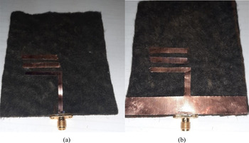
Finally, the proposed wearable high-gain dual-band antenna was manufactured to prove the simulations and designs. Figure 6 shows a sample of the fabricated proposed antenna. The connector used is R127632001 type, SMA 2.9, Radiall brand connector is used to measure the parameters of this antenna. The measurements were conducted using the Agilent network analyzer HP872. The final dimensions of the fabricated antenna are 80 × 92 × 2 mm3, which makes it a good choice for use in medical/communications systems.
A photograph of the manufactured antenna; (a) top view and (b) bottom view.

In Fig. 7(a), the simulated and measured return loss of the proposed wearable antenna is shown. It is observed that the frequency ranges of 1.7–2.5 and 5.2–6 GHz are covered. This parameter is measured after calibrating the network analyzer with the highest accuracy. Figure 7(b) shows the gain of the proposed antenna. The measured gain of this antenna at 2 and 5.8 GHz is 8.2 and 9.75 dB, respectively. The discrepancy between the simulated and measured results is ascribed to the manufacturing tolerance.
(a) Simulated and measured antenna frequency responses; (a) return loss and (b) gain.

In Fig. 8, the simulated and measured radiation patterns of the proposed antenna are reported for both E- and H-planes at 2 and 5.8 GHz. The yielded results are achieved in a chamber antenna room by placing a transmitter horn antenna. The proposed wearable antenna was assumed as the receiver antenna. It can be seen that there is an acceptable fit between the results of measurement and simulation.
Simulated and measured radiation patterns of the proposed wearable antenna for E- and H-planes at frequencies; (a) 2 GHz and (b) 5.8 GHz.

Figure 9 also shows a three-dimensional (3D) radiation pattern at frequencies 2 and 5.8 GHz to have a better view of antenna radiation. It is clear that the proposed antenna is an end-fire, high-gain, and dual-band antenna.
3D radiation patterns of the antenna at frequencies; (a) 2 GHz and (b) 5.8 GHz.

To make the advantages of the proposed antenna more visible, as well as to present a comparison between the performance of this design and other antennas introduced in the references, Table 1 is provided. Among the advantages of the proposed antenna are its high gain, suitable bandwidth, as well as wearability.
Performance comparison of the proposed antenna with other works

Conclusion
In this paper, a wearable, high-gain, and dual-band antenna were designed and manufactured using the proposed TTLs technique. The two frequency bands covered by this antenna include frequency ranges of 1.7–2.5 and 5.4–5.95 GHz for use in communications/medical systems such as DCS, PCS, UMTS, Wibro, WLAN + Bluetooth + ISM, and HIPERLAN2. The measured gain at 2 and 5.8 GHz is 8.2 and 9.75 dB, respectively. The advantages of this antenna include high gain, wide bandwidth, and simple design. It should be noted that the simulated and measured results of the characteristics of the proposed antenna are in good proportion to each other.
 Farzad Khajeh-Khalili was born in Isfahan, Iran, in 1989. He received the Ph.D. degree with the highest honors in Telecommunication Engineering from the Islamic Azad University, Najafabad Branch, Iran in 2019. Since 2018, he is a faculty member of the Kian Institute of Higher Education, Shahin Shahr, Isfahan, Iran, as the head of the Electrical Engineering Department. Dr. Khajeh-Khalili is a member of Iran's National Elites Foundation. Also, he is the Editor-in-Chief of the Kian Journal of Electrical Engineering (KJEE) in Iran. He has also been the reviewer of several articles in scientific and authoritative journals and has published more than 20 papers in prestigious journals and conferences. His research interests include metamaterials, power dividers, microstrip MIMO antennas, wearable components, microwave devices, circuits, and subsystems.
 Ali Shahriari was born in Isfahan, Iran, in 1997. Shahriari received the B.Sc. degree in Electronics Engineering from the Isfahan Jahad Daneshgahi in 2019. He is currently working toward the biomedical projects at Kian Institute of Higher Education. His research interests include wearable antennas, MIMO antennas, and microstrip filters.
 Fatemeh Haghshenas was born in Isfahan, Iran, in 1996. She received the B.Sc. degree in Bioelectric Engineering from the Isfahan Jahad Daneshgahi in 2019. She is currently working toward the biomedical projects at Kian Institute of Higher Education. Her research interests include wearable components, metamaterials, and microstrip designs.