I. INTRODUCTION
Heat treatment is a crucial step in the processing route of different types of steels. The precise control of heat treatment can improve the mechanical properties and microstructure. Generally speaking, heat treatable steels are those which have tendency for the martensitic transformation through quenching of austenite. The martensitic stainless steels (MSSs) are a major group of high-alloy heat treatable steels which provide high strengths and good corrosion resistance for some industrial applications such as steam turbine blades, valves, shafts, screws, and plastic molds. Reference Lim, Lai and Ma1,Reference Tsai, Chiou, Du and Yang2 Their successful performance necessitates a good combination of strength and ductility which is acquired by a precise control of heat treatment. The heat treatment for MSSs includes austenitization, quenching, and tempering. While austenitization-quenching leads to a hard martensitic structure with low ductility, tempering restores ductility at the expense of hardness and provides a desired combination of hardness and ductility. Therefore, a sort of parameters in austenitization-quenching and tempering steps affects the mechanical properties. Reference Xu, Yan, Liu, Li, Ning and Qiao3,Reference Ping, Ohnuma, Hirakawa, Kadoya and Hono4
The formation of a single-phase austenitic structure and the dissolution of carbides and other phases are the major aims of austenitizing. For this purpose, the austenitizing temperature should be high enough to dissolve all carbides into austenite. Reference Nasery Isfahany, Saghafian and Borhani5 On the other hand, chromium carbides which are often present in MSSs control the grain growth and participate in the formation of finer austenite structure before quenching. Reference Kim and Kim6 The finer austenite grain size which is obtained at lower austenitization temperatures leads to the finer martensite units or packets which provide higher strength and toughness. Reference Morito, Saito, Ogawa, Furuhara and Maki7,Reference Wang, Wang, Shi, Hui and Dong8 Such opposite effects of austenitization temperature has been a challenge for the proper design of heat treatment for MSSs. Reference Ebrahimi, Keshmiri and Momeni9 In addition, some other parameters such as quenching rate have been found influential on the structure and mechanical properties of as-quenched martensite. Reference Tsai, Chiou, Du and Yang2
As mentioned, tempering is the second step of heat treatment in MMSs which is designed to provide a desired combination of toughness and strength. Reference Tamura, Harughuchi, Yayashita, Nagaoka, Ohinata, Ohnishi, Itoh, Ito, Shinozoka and Eska10 The recovery of dislocations and exit of supersaturated carbon leads to the partial transformation of martensite into ferrite which imparts lower strength and higher toughness to the tempered MSS. Reference Kennett, Krauss and Findley11 However, there are several investigations showing that some tempering regimes increase hardness and degrade fracture toughness. Reference Reguly, Strohaecker, Kraus and Matlock12,Reference Wang, Zhong, Rong, Hsu (Z.Y. Xu) and Wang13 Such anomalous behavior, termed as embrittlement or secondary hardening, has been attributed to the precipitation of new carbides. Reference Wang, Zhong, Rong, Hsu (Z.Y. Xu) and Wang13–Reference Chakraborty, Das, Albert, Bhaduri, Thomas Paul, Panneerselvam and Dasgupta15 It is manifest that the extent of secondary hardening depends on the dissolution of primary carbides through austenitization. Reference Hsu, Teng and Lee16 The undesired regimes of embrittlement should be determined and avoided in the processing route of MSSs. This is because the formation of secondary carbides not only decreases the fracture toughness, but also degrades the corrosion resistance of MSSs by depleting Cr from the matrix. Reference Lim, Lai, Ma, Northwood and Miao17–Reference Furuhara, Kobayashi and Maki20
In current research, the influence of austenitizing treatment on the mechanical properties of as-quenched martensite in AISI 410 and Ni-bearing 410 (often called AISI 414) MSSs has been investigated and related to the dissolution of carbides. In the next step, the effect of tempering on the strength and toughness was investigated and the regimes of secondary hardening were related to the carbides precipitation in the steels.
II. MATERIALS AND METHODS
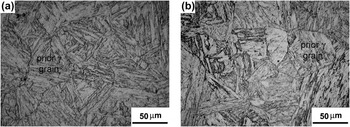
The chemical composition of AISI 410 and Ni-bearing 410 MSSs, which are called 410 and 410 Ni later on, are given in Table I. The samples of both steels with nearly identical grain size (Fig. 1) and hardness were austenitized at 900, 980, 1010, 1050, and 1100 °C for 1 h and then quenched in water to the ambient temperature. The as-quenched specimens were then prepared by the standard metallographic techniques and etched in the Villella’s reagent (1 g picric acid, 5 mL HCl, 100 mL ethanol) to reveal the prior austenite grain boundaries. The Clemex software was used to determine the average grain size of prior austenite in the heat treated samples. The microstructures were characterized by the optical microscopy and the average grain size of the samples was determined based on the ASTM E112. To follow the influence of austenitizing on the dissolution of carbides, Rockwell C hardness testing and X-ray diffraction (XRD) measurements were performed on the as-quenched samples. Based on the grain size measurements, hardness testing and XRD results the best temperature for austenitizing was determined as 1050 °C.
Chemical composition of MSSs used in this investigation.

Starting microstructures of the studied alloys: (a) 410 and (b) 410 Ni.

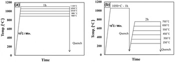
For the second step of heat treatment, the samples of both steels were austenitized at 1050 °C and then tempered for 2 h in temperature range of 250–650 °C with the interval of 50 °C. Figure 2 exhibits the schematic representation of the thermal cycles adopted for the first and second steps of heat treatment in this investigation. The mechanical properties of the tempered samples were evaluated by tensile testing (according to ASTM E8M) with the cross-head speed of 1 mm/min and impact tests (according to ASTM E23) at −18 °C. Field emission scanning electron microscope (FESEM; model TSCAN, Carl Zeiss AG, Jena, Germany) was used to characterize the microstructures and fracture surface of the tensile test samples.
Schematic representation of the heat treatment steps applied on the samples: (a) austenitization and (b) tempering.

III. RESULTS AND DISCUSSION
A. Effect of austenitizing temperature on as-quenched microstructure and hardness
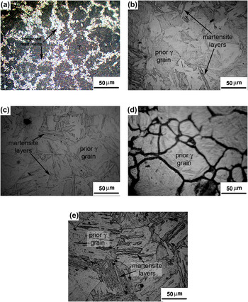
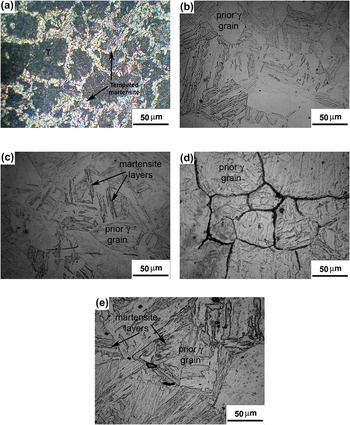
Figures 3 and 4 show the prior austenite grain structure in the samples after austenitization at various temperatures and quench in water. Most of the micrographs show a martensitic structure in which the prior austenite grain boundaries have been partly revealed by the Vilella’s reagent. However, the both steels show a light phase network along the prior austenite grain boundaries after austenitizing at 900 °C. Since δ-ferrite is often observed as discrete islands in MSSs, Reference Wang, Lu, Xiao, Li and Li21,Reference Cardoso, Kwietniewski, Porto, Reguly and Strohaecker22 the light phase which has decorated the prior austenite grain boundaries in Figs. 3(a) and 4(a) seems to be the untransformed martensite which has been tempered at the studied temperature. The plate-like morphology of this phase supports this idea. The microhardness values of 276 and 475 HV for the light and dark phases confirmed that the lighter phase has been tempered at the austenitization temperature.
Prior austenite grain structure in 410 MSS after austenitization at various temperatures of (a) 900 °C, (b) 980 °C, (c) 1010 °C, (d) 1050 °C, and (e) 1100 °C and quenching in water.

Prior austenite grain structure in 410 Ni MSS after austenitization at various temperatures of (a) 900 °C, (b) 980 °C, (c) 1010 °C, (d) 1050 °C, and (e) 1100 °C and quenching in water.

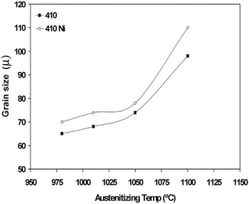
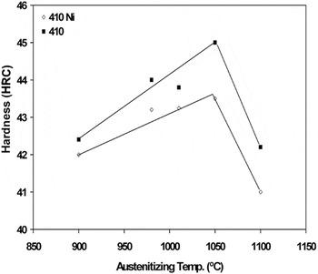
The previous investigations have declared that dual-phase microstructures in DSSs such as the coexistence of δ-ferrite with austenite are deleterious for the fracture toughness of MSSs by facilitating the cracks formation and propagation along the matrix/δ-ferrite interfaces. Reference Wang, Lu, Xiao, Li and Li21,Reference Cardoso, Kwietniewski, Porto, Reguly and Strohaecker22 It has been understood that δ-ferrite promotes the nucleation and coalescence of microvoids and facilitates fracture even at high temperatures. Reference Lin, Deng, Jiang, Wen and Liu23,Reference Lin, Deng, Jiang, Wen and Liu24 It seems that austenitization at higher temperatures, i.e., over 900 °C, should be preferred due to the formation of a uniform martensitic structure in the as-quenched material. Figure 5 presents the phase diagrams of the steels calculated by the Thermocalc software. It is observed that δ-ferrite, austenite, M23C6, and M7C3 carbides are the constituent phases of in the austenitization temperature range. It is also worthy to note that the addition of 1 wt% Ni has no considerable effect on the phase regions (Fig. 5) or the microstructural evolutions through austenitization (Figs. 3 and 4). Figure 5 also shows that the maximum temperature for austenitization is about 1100 °C; because at temperatures beyond 1100 °C microstructure consisted of δ-ferrite and carbides. It is also worthy to note that the complete dissolution of carbides in both the steels needs heating up to temperatures well above 1100 °C where the microstructure becomes fully ferritic. Therefore, the austenitizing within the adopted temperature range would reduce the amount of carbides by dissolving them into austenite. On the other hand, although increasing the austenitizing temperature leads to the better dissolution of carbides in the matrix, it would also accelerate the growth of austenite grains, which is undesirable. For this purpose, the variations of austenite grain size and hardness with the austenitization temperature were determined as shown in Figs. 6 and 7. It is observed that austenitization in range of 900–1050 °C does not considerably change the prior austenite grain size. This implies that the carbides could effectively inhibit the austenite grain growth up to 1050 °C. According to the phase diagrams in Fig. 5, by heating the steels above 1050 °C, austenite and M23C6 carbides transform to δ-ferrite and M7C3 and finally to δ-ferrite, through the following steps:
 $$\delta + \gamma + {{\rm{M}}_{23}}{{\rm{C}}_6}{\rm{\ }}\buildrel {{{1070}^ \,\,\circ }{\rm{C}}} \over \longrightarrow \delta + {{\rm{M}}_{23}}{{\rm{C}}_6}\buildrel {{{1080}^ ,\,\circ }{\rm{C}}} \over \longrightarrow \delta + {{\rm{M}}_7}{{\rm{C}}_3}\buildrel {{{1100}^ ,\,\circ }{\rm{C}}} \over \longrightarrow \delta$$
Equilibrium phase diagram for the alloys 410 and 410 Ni calculated by Thermocalc software.

Prior austenite grain size with temperature.

Hardness measurement of quenched specimens after austenitization.

By disintegrating austenite more Cr and C are dissolved into δ-ferrite and diffuse toward the M23C6 carbide particles. This in turn accelerates the particles coarsening at temperatures higher than 1050 °C and decreases their pinning effect on the boundaries. As a conclusion, there is an interrelation between transformation of austenite to δ-ferrite, average grain size and carbides evolution. The hardness measurements in Fig. 7 show that by austenitizing at temperatures beyond 1050 °C hardness drops due to the fast coarsening of grains and carbide particles. It is also worthy of attention that the existence of 1 wt% Ni in 410 Ni cannot compensate its lower hardness due to the lager grain size comparing to 410.
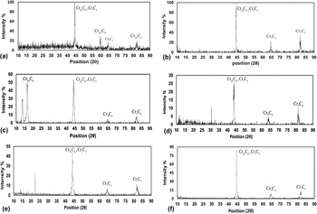
XRD measurements of the samples austenitized at 1010, 1050, and 1100 °C in Fig. 8 shows that the amount of carbides decrease with increasing temperature. It is also observed that the peak intensities are relatively larger for 410 Ni. This can be attributed to the effect of Ni on decreasing the solubility of Cr in the matrix. In other words, Ni forces Cr to more take part in the formation of carbides instead of being soluble in the matrix. Therefore, it is manifest that the amount of carbides in 410 Ni should be slightly higher than 410. The increase in the intensity of the peaks pertaining to Cr7C3 and the decrease in those of Cr23C6 with increasing temperature are in agreement with the previous results. However, the appearance of Cr23C6 peaks in the spectrums of 410 Ni is referred to the effect of Ni on postponing the transformation of austenite to δ-ferrite.
XRD patterns of carbides present in 410 Ni (a, c, and e) and 410 (b, d, and f) after austenitization at (a, b) 1010 °C, (c, d) 1050 °C and (e, f) 1100 °C.

B. Effect of tempering temperature on microstructure, mechanical properties, and fracture behavior
After austenitization and quenching, the steels possess high strength and low ductility. Tempering is a complementary heat treatment which often aims at reaching a desirable combination of hardness and ductility. Reference Wang, Zhong, Rong, Hsu (Z.Y. Xu) and Wang25 To study the tempering behavior of the steels 410 and 410 Ni, the samples were austenitized at 1050 °C and then tempered in temperature range of 250–650 °C.
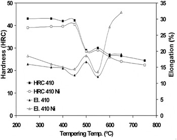
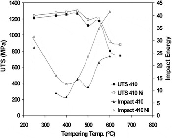
Figure 9 shows the variations of hardness and elongation of the specimens tempered at different temperatures. The continual decrease in hardness and corresponding increase in elongation imply that the ductility of both steels improves at the expense of strength. The same results are inferred from the variations of ultimate tensile strength (UTS) and Charpy impact energy in Fig. 10. By tempering at low temperatures, dislocations formed during the displacive transformation of austenite to martensite are annihilated by recovery. This, in turn, alleviates the internal residual stress in martensite and decreases hardness. At higher temperatures, the recovery is accelerated and proceeds with diffusing carbon out of the martensite layers. Reference Kruss26 While the carbon atoms make clusters of carbide particles inside or outside the layers, martensite gradually turns into ferrite. Therefore, except for the temperatures corresponding to the formation of carbides, the continual decrease in the hardness continues until a ferritic matrix is formed. Reference Kruss26
Variation of hardness and elongation with tempering temperature.

Variation of UTS and Charpy impact energy with tempering temperature.

It is evident that the existence of Ni has improved the ductility and toughness of 410 Ni, comparing to 410. Therefore, the assignment of 410 Ni can be helpful for industrial parts which need high strength as well as acceptable fracture toughness. The improvement of ductility and toughness by adding Ni can be attributed to increase in the stacking fault energy (SFE) of the steel. As Ni is a high SFE metal, Reference Ebrahimi, Momeni, Abbasi and Monajatizadeh27 it increases the SFE value of 410 and therefore facilitates the dislocation glide. The variation of mechanical properties with tempering temperature in Figs. 9 and 10 introduce two critical temperatures at the inflection points of the curves. The results of hardness measurement in Fig. 9 indicate that the strength of both materials increase by tempering at 450 and 550 °C; Whereas, tempering at other temperatures leads to the abrupt decrease in strength. Tempering at these temperatures is accompanied by a similar increase in UTS and decrease in ductility and fracture toughness. These changes may be associated with the secondary precipitation of chromium carbides as reported in the literature. Reference Wang, Zuo, Sun, Li, Liu, Yang, Shen and Huang28–Reference Yang, Lee and Kwon31 As mentioned in the previous section, austenitizing at 1050 °C effectively decrease the volume fraction of pre-existing carbides by dissolving them into the austenitic matrix. Therefore, the austenite at high temperatures is enriched in alloying elements and more withstand against the displacive martensitic transformation. This in turn depresses the martensite start temperature, Ms , leading to more remained austenite after quenching. During tempering at low temperatures, the remained austenite decomposes to a mixture of ferrite and cementite. Reference Kruss26 As this mixture is harder than austenite, the hardness and UTS increase and ductility and toughness adversely decrease. It has been observed that the decomposition of retained austenite and the diffusion of supersaturated carbon out of martensite simple carbides propel the formation of some simple carbides of types M2C or M3C which increase hardness and degrade ductility. Reference Kruss26 Therefore, the restoration of hardness and UTS and degradation of ductility and toughness in samples tempered at about 450 °C can be attributed to the decomposition of austenite and formation of primary carbides in both steels. By tempering at higher temperatures the primary carbides are dissolved, leading to the amelioration of impact and elongation properties Reference Asgari, El-Danaf, Shaji, Kalidindi and Doherty32 and new more stable and more complex carbides of M7C3 or M23C6 are formed and increase hardness to the second peak, which is observed around 550 °C.
Figure 11 shows the FESEM images of the carbides formed during tempering at different temperatures. Figures 11(a) and 11(b) show that tempering at 450 °C does not lead to the formation of large carbide particles. However, based on the discussion of Figs. 9 and 10 some very small primary carbides (d < 50 nm) would be responsible for the increase in strength and decrease in ductility and toughness. Figures 11(c) and 11(d) show two sets of carbide particles with different sizes in both steels. The fine precipitates (d < 50 nm) which are observed within the martensite layer are the primary carbides and the larger ones which are observed between the martensite layers are the secondary carbides. During tempering at low temperatures, i.e., below 450 °C, trapped carbon atoms take the opportunity to get out of martensite structure and form some clusters of primary carbides within the martensite layers. Reference Kruss26 By tempering at higher temperatures, i.e., 550 and 650 °C, such clusters are dissolved and the more stable carbide particles precipitate at the interface of the martensitic layers. The comparison of Figs. 11(e) and 11(f) reveals that the secondary carbides have occupied the interfaces of the martensitic layers. Chakraborty and his coworkers showed that the small carbides particles which are formed at low temperature tempering (around 450 °C) are of type M2C (M is a participation of all carbide forming elements). Reference Chakraborty, Das, Albert, Bhaduri, Thomas Paul, Panneerselvam and Dasgupta15 They also found that Fe has a greater role than other alloying elements in such carbides. It was found that by increasing the tempering temperature the primary carbides are replaced with new carbides of M23C6 which are richer in Cr. Reference Chakraborty, Das, Albert, Bhaduri, Thomas Paul, Panneerselvam and Dasgupta15
FESEM images of the samples of 410 (a, c, e, and g) and 410 Ni (b, d, f, and h), tempered at (a, b) 450 °C, (c, d) 550 °C, (e, f) 650 °C, and (g, h) magnified views of e and f.

In agreement with the XRD results in Fig. 8, Fig. 11 also shows that 410 Ni has larger particles than 410. As discussed, Ni reduces the dissolution of Cr in the matrix and feed carbides with more Cr and C atoms. Figures 11(g) and 11(h) show the magnified view of primary and secondary carbides in the studied steels. More primary carbides within the martensite layers in 410 [Fig. 11(g)], comparing to 410 Ni [Fig. 11(h)] indicates that the rate of tempering in 410 Ni is faster than 410.
The typical SEM images from the fractured surfaces of the tensile samples are shown in Fig. 12. The micrographs of Figs. 12(a) and 12(b) clearly show large dimples on the fracture surfaces of samples tempered at 250 °C. In agreement with the results of Figs. 9 and 10, these observations indicate that both steels bear ductile fracture after tempering at low temperatures. For the samples tempered at 450 °C, Figs. 12(c) and 12(d) show that different mechanisms should be prevailing. While Fig. 12(c) shows a brittle fracture with cleavage characteristics for 410, Fig. 12(d) indicates that intergranular fracture is the dominant fracture mechanism for 410 Ni. Based on this observation, the better ductility and toughness of 410 Ni, reported in Figs. 9 and 10, can be attributed to the plastic deformation which occurs during the intergranular fracture. It is clear that the intergranular fracture in 410 Ni is related to the existence of Ni. The previous investigations have shown that the intergranular fracture occurs when the grain boundary is weakened by the segregation of detrimental elements such as S or P. Reference Briant and Banerji33 There are some reports that S tends to segregate to grain boundaries in Ni-based or Ni-bearing alloys. Reference Kiely, Yeh and Bonnell34–Reference Mulford36 In addition, the presence of S has been found responsible for grain boundary weakening in some Ni-containing alloys. Reference Mohammadi Shore, Morakabati, Abbasi and Momeni37,Reference Abbasi, Morakabati, Mahdavi and Momeni38 It is interesting to note that Ni has the highest grain boundary energy (γgb) among FCC metals such as Ag, Al, Au, and Cu. Reference Humphreys and Hatherly39 Besides, Najafabadi et al. Reference Najafabadi, Wang, Srolovitz and LeSar40 suggested that the segregation of Ni atoms to the grain boundaries increase γgb in Ni–Al alloys. Consequently, it can be proposed that higher γgb in 410 Ni increases the propensity for the segregation of S to the grain boundaries, giving rise to grain boundary weakening and decohesion in tension.
SEM images from the fractured surfaces of 410 (a, c, and e) and 410 Ni (b, d, and f) tempered at (a, b) 250 °C, (c, d) 450 °C, and (e, f) 650 °C.

Figures 12(d) and 12(e) represent the fracture surfaces of the samples tempered at 650 °C. It is obvious that 410 has broken with a brittle mechanism which is attributed to the existence of secondary carbides. However, the micrograph of 410 Ni shows a dual mechanism of cleavage-intergranular fracture as arrowed in Fig. 12(e). As shown in Fig. 11, tempering at 650 °C leads to the formation of secondary carbides which increase the tendency for cleavage fracture. However, the segregation of S to the prior austenite grain boundaries increases by increasing the tempering temperature. This in turn leads to a competition between the crystalline and grain boundary routes of cracking in 410 Ni.
IV. CONCLUSIONS
In this research, the effect of austenitization and tempering on the microstructure and mechanical properties of 410 and 410 Ni MSSs was investigated. The major results are summarized as follows:
-
(1) In both steels, austenitization at 900 °C leads to remaining a tempered martensite network on the prior austenite grain boundaries.
-
(2) At temperatures over 1050 °C, austenite gradually transforms to δ-ferrite.
-
(3) The grain size and hardness measurements showed that austenitization at 1050 °C leads to the partial dissolution of carbides without a considerable growth of austenite grains. However, austenitization at temperatures beyond 1050 °C resulted in a dramatic drop in hardness due to fast grain growth.
-
(4) The mechanical tests (tensile, hardness, and impact) showed that tempering at 450 and 650 °C leads to increase in strength and decrease in ductility and toughness due to the formation of primary and secondary carbides. The ductility and fracture toughness were better for 410 Ni comparing to 410.
-
(5) The fractured surfaces showed that both steels tend to ductile fracture after tempering at low temperatures. At high tempering temperatures, however, 410 showed a brittle fracture; 410 Ni exhibited a dual intergranular-brittle fracture mechanism.