1. Introduction
With the successful launch of the wireless standard Qi by the Wireless Power Consortium (WPC) comprising over 660 companies by January 2019, wireless charging of portable consumer electronics [Reference Hui1] has already gained wide-spread acceptance not only in the forms of wireless charging pads used in office and domestic applications and also installed in vehicles. Presently, the Qi standard focuses on the use of planar receiver coil primarily designed for one-dimensional (1-D) wireless power transfer (WPT). It should be noted that wireless charging standard does not restrict wireless charging applications. In fact, WPC is expanding its scope to cover not only mobile phones, but also notebook computers, electric hand tools and even kitchen electric appliances [2]. Therefore, there is strong motivation to investigate other forms of WPT structures because international wireless charging standards will continue to evolve with the demands of new applications.
Recently, omnidirectional WPT has also attracted much attention. In references [Reference O'Brien3–Reference Ghotbi, Najarzadegan, Ashtiani, Shoaei and Shahabadi9], multiple orthogonal coils are used as three-dimensional (3-D) transmitter coil structures. In [Reference O'Brien3 Reference Jonah, Georgakopoulos and Tentzeris4], 3-D receiver coil structures are adopted with their respective 3-D transmitter coil structures for WPT. In contrast, [Reference Ng, Zhang, Lin and Hui5–Reference Lin, Zhang and Hui8] consider the situations of using a 1-D planar receiver coil structure for a 3-D transmitter coil structure.
This paper focuses on the compatibility of 3-D receiver coil structures with a 1-D planar transmitter coil structure. In particular, it is the “slim” 3-D receiver coil structures that are of special interest in this comparative study because many electronic products prefer to accommodate slim receiver module due to their form factor restrictions.
3-D receiver coil structures have been reported in several articles. 3-D receiver coil structures of equal length (i.e. either in cubic or spherical form) in three dimensions are most common and have been used in [Reference O'Brien3] and [Reference Jonah, Georgakopoulos and Tentzeris4]. Reference [Reference Ghotbi, Najarzadegan, Ashtiani, Shoaei and Shahabadi9] uses a 3-D receiver with a rectangular coil structure for use inside a cylindrical solenoid transmitter. Although 3-D receiver coil structures have been studied previously, the emphasis on “slim” 3-D receiver coil structures for compatibility with 1-D planar transmitter coil has not been investigated in detail for use with a 1-D transmitter coil. Reference [Reference Li, Li, Xie, Huang and Wang10] considers the use of a 3-D receiver coil structure with a planar transmitter coil, but the 3-D receiver module is of the cubic form and does not fit into the slim receiver structure requirement in this study. An interesting recent WPT development is the idea of using multiple dipole receiver coil designs to provide high degree of freedom of positioning for 1-D to 3-D applications [Reference Choi, Lee, Sohn, Jang and Rim11].
In this paper, three types of slim receiver coil structures for 3-D use with a 1-D planar transmitter coil are studied and compared. In order to evaluate their performance, the mutual coupling coefficient will be used as an indicator. The merit factor includes the consistency of the mutual coupling factor between the receiver module and the transformer coil under different angular orientations and distances between the transmitter coil and the receiver modules. Both finite-element simulation and experimental tests are used to verify the comparative results.
2. The slim 3-D receiver structures
To enable omnidirectional WPT, we could use either a 3-D transmitter coil structure as proposed in [Reference Zhang, Lin and Hui6] which can generate magnetic fluxes in a 3-D manner or a 3-D receiver coil structure which basically can receive fluxes from any direction [Reference O'Brien3] (Fig. 1). This paper focuses on slim 3-D receiver coil structures which can build up an effective WPT coupling with an ordinary planar transmitter coil at an arbitrary position.
Diagram of a traditional 3-D receiver coil structure [Reference O'Brien3].

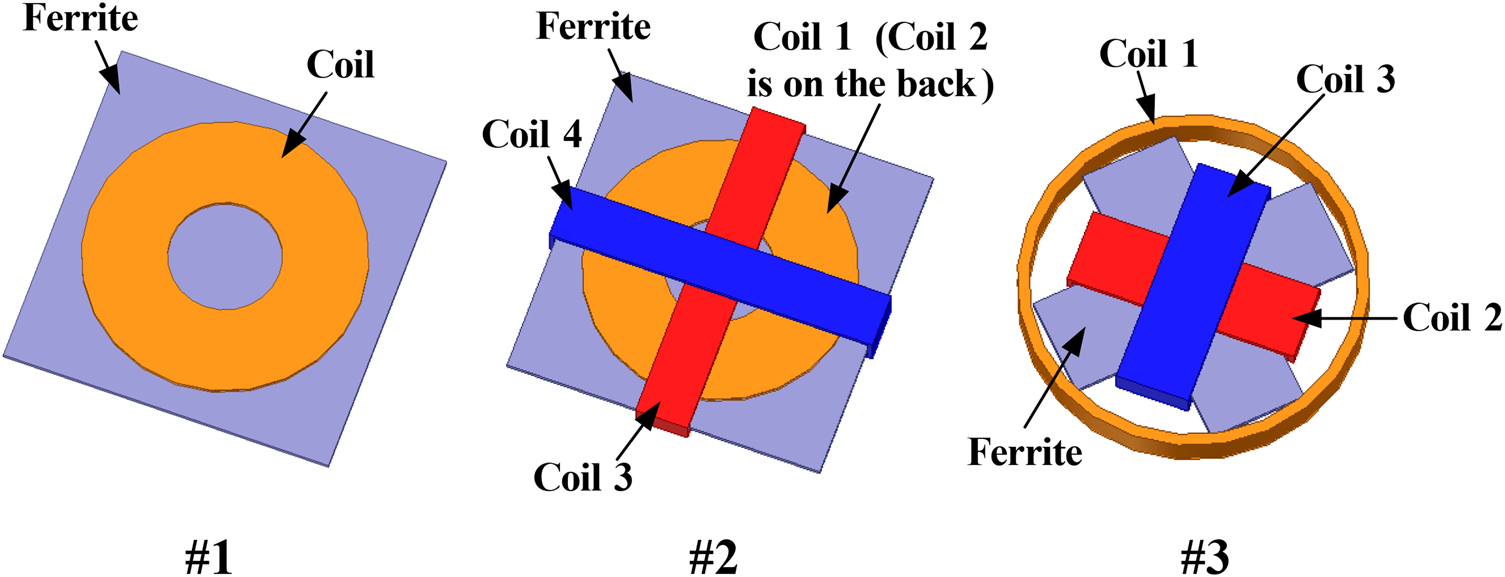
Figure 2 shows three types of slim receiver coil structures to be evaluated for 3-D use of a 1-D planar transmitter coil.
• Structure #1 consists of a planar spiral coil mounted on a ferrite plate and is used essentially as a reference for comparison.
• Structure #2 has four coils, with two planar spiral coils placed on both side of the ferrite plate and two concentrated coils wound along the two central lines of the ferrite plate.
• Structure #3 has a cross-shaped ferrite structure with a circular concentrated coil forming the circumference of a circular receiver and two orthogonal concentrated coils forming another cross structure.
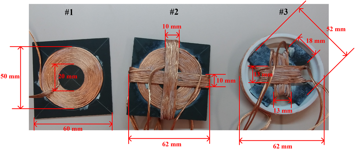
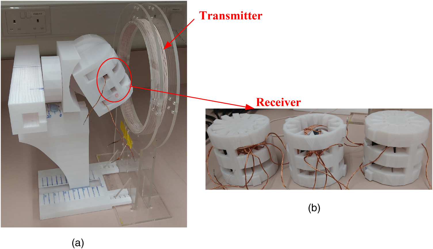
In order to make a comparative study, the dimensions of these structures should be as close to one another as possible. Three experimental prototypes have been constructed and their top views are shown in Fig. 3, while their side views shown in Fig. 4. An adjustable mechanical system has been built to keep the position of the receiver modules for the tests in the presence of the transmitter coil as shown in Fig. 5.
Diagrams of three slim 3-D receiver coil structures.

Top views of the three slim receiver coil structures (with dimensions).

Side views of the three slim receiver coil structures (with dimensions).

Photographs showing (a) an adjustable mechanical system for holding the receiver module in position and (b) the corresponding 3 receivers.

3. Circuit topologies and theoretical analysis
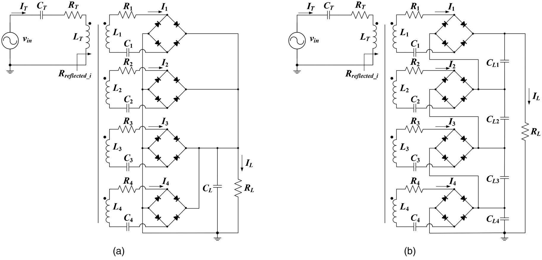
Figure 6 shows the two possible circuit topologies for a WPT system using a slim 3-D receiver consisting of multiple coils. The outputs of the receiving coils can be either in parallel or in series.
The circuit topology of the WPT system with a single-coil transmitter and a multi-coil receiver when (a) the outputs are connected in parallel and (b) the outputs are connected in series.

For the parallel-output connection, we use L T to represent the self-inductance of the transmitter coil and L i, M i (i= 1, 2, …) to represent the self-inductance of the i th receiver coil and the mutual inductance between the i th receiver coil and the transmitter coil, respectively. Then, in the i th receiver coil, we have
 $$j\omega M_iI_T + R_iI_i + V_{Li} = 0$$
where the voltage drop of the diodes is neglected, the current in the receiver coil is set as the reference (i.e. with a zero phase angle), I T is the current phasor in the transmitter coil and V Li is the root mean square value of the fundamental component of the input voltage of the full-bridge rectifier. If the receiver current can be considered continuous, V Li is given by
 $$V_{Li} = \displaystyle{{2\sqrt 2} \over \pi} V_L$$
where V L is the output voltage applied to the load R L.
From (1), we can see that if the induced voltage in the receiver coil |jωM iI T| is lower than the output voltage V Li, then there will be no current in this receiver coil. If the induced voltage is higher than V Li, then the current in the receiver coil is given by
 $$I_i = \displaystyle{{\omega M_iI_T-V_{Li}} \over {R_i}}$$
and thus, the equivalent load resistance for this receiver coil can be derived as
 $$R_{Li} = \displaystyle{{V_{Li}} \over {I_i}} = \displaystyle{{V_{Li}R_i} \over {\omega M_iI_T-V_{Li}}}$$
It can be seen from (4) that a weaker mutual coupling leads to a larger equivalent load resistance. Recall that the reflected resistance R reflected_i at the primary side, which is the equivalent resistance seen from the transmitter coil, with the coil resistance neglected, is given by
 $$R_{{\rm reflected}\_i} = \displaystyle{{\omega ^2M_i^2} \over {R_{Li}}}$$
Therefore, a larger R Li leads to a smaller reflected resistance in the transmitter coil. So the power delivered to the receiver coil with a weaker mutual coupling will be lower assuming the transmitter coil current is constant. Eventually, by using this circuit topology, the receiver coil with a stronger coupling with the transmitter coil will deliver more power than the one with a weaker coupling and thereby, the efficiency of the whole system can be maintained high.
For the series-output connection, we firstly assume the i th receiver coil can generate a non-zero voltage V Li on its output capacitor C Li. The load current is I L. The circuit equation is the same as (1) and the equivalent load resistance is given by
 $$R_{Li} = \displaystyle{8 \over {\pi ^2}}\displaystyle{{V_{Li}} \over {I_L}}$$
and the receiver coil current is given by
 $$I_i = \displaystyle{\pi \over {2\sqrt 2}} I_L$$
By substituting (7) into (1), we get
 $$V_{Li} = \omega M_iI_T-\displaystyle{\pi \over {2\sqrt 2}} R_iI_L$$
By substituting (8) into (6), we get
 $$R_{Li} = \displaystyle{8 \over {\pi ^2}}\displaystyle{{\omega M_iI_T-(\pi /2\sqrt 2 )R_iI_L} \over {I_L}} = \displaystyle{8 \over {\pi ^2}}\omega M_i\displaystyle{{I_T} \over {I_L}}-\displaystyle{{2\sqrt 2} \over \pi} R_i$$
It can be seen from (9) that for a given I T, the equivalent load resistance of a receiver coil is proportional to the mutual inductance between the receiver coil and the transmitter coil which is different from that of the parallel-output case. Therefore, we can predict that this series-output connection might have a lower system efficiency than the parallel-output connection. However, it might generate higher output power under the same operation conditions, since the reflected load resistance of this series-output connection is larger.
4. Simulation and experimental verifications
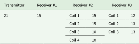
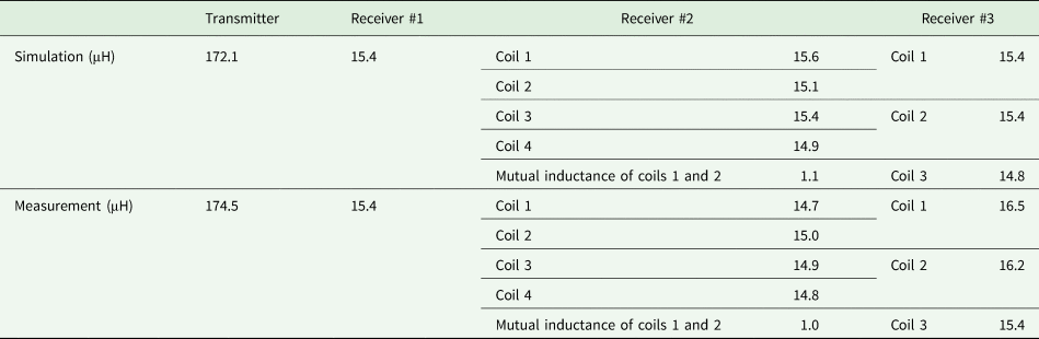
Simulations and measurements are carried out based on the coils and circuits described above. Tables 1–3 show the details of the practical coils. A 2 Ω power resistor is used as the load. The diodes of the diode bridges are the Schottky barrier diodes with a forward voltage of 0.39 V.
Number of turns in the coils

Coil inductances at a frequency of 100 kHz

Measured coil resistances at a frequency of 100 kHz

The coupling coefficients between the transmitter and the receivers, as well as the system efficiencies of using the circuits in Fig. 6, with different coupling positions (i.e. different distances and different angles) are shown in Fig. 7. Totally eight positions are investigated. The first four positions are
(1) the receiver is aligned to the center of the transmitter coil and the angle between the receiver plane and the transmitter plane is zero, as shown in Fig. 7(a);
(2) the receiver is aligned to the center of the transmitter coil and it rotates 45° around its Y axis, as shown in Fig. 7(b);
(3) the receiver is aligned to the center of the transmitter coil and it rotates 45° around both of its Y and X axes, as shown in Fig. 7(c);
(4) the receiver is aligned to the center of the transmitter coil and it rotates 90° around its Y axis, as shown in Fig. 7(d).
Simulated and measured results of the coupling coefficients and system efficiencies at different relative positions (#1: the ordinary single-coil receiver; #2: the proposed multi-coil receiver with a square ferrite plate and #3: the proposed multi-coil receiver with a cross-shaped ferrite plate. The solid lines represent simulation results, and the dots represent practical measurement results).

Then the receiver is moved to align to the edge of the transmitter coil and the same rotations are realized as described above. The distance in Fig. 7 represents the distance from the top surface of the transmitter coil to the center of the receiver.
For each position, the finite element analysis simulation models of using #2 and #3 receivers (e.g. the top row of Fig. 7(a)-1), the coupling coefficients for using three receivers (e.g. the bottom row of Fig. 7(a)-1), and the system efficiencies of using parallel-output and series-output connections (e.g. Figure 7(a)-2) are given. The efficiency of using the single-coil receiver coaxially aligned with the transmitter is also provided in all of the efficiency figures for comparison.
The following important observations should be noted:
• For #1, k is very close to zero when the coil is placed at the center of the transmitter coil at 90o (Fig. 7(d)), as the two coils are perpendicular and the fluxes generated by the transmitter coil will not penetrate #1. k is also very low when the coil is placed at the edge of the transmitter coil at 0° (Fig. 7(e)), because at this position, the fluxes generated by the transmitter coil will be basically parallel with the XY plane and thus will not penetrate #1. At these two positions, coil 4 of #2 and coil 2 of #3 which are orthogonal to #1, provide much stronger couplings with the transmitter coil. This verifies the idea of the proposed slim 3-D receiver coil structures.
• #2 and #3 can achieve higher efficiency than #1 at almost all of the positions, with either the parallel-output connection or the series-output connection.
• The parallel-output connection can achieve higher efficiency compared with the series-output connection as explained in the last section.
5. Discussion
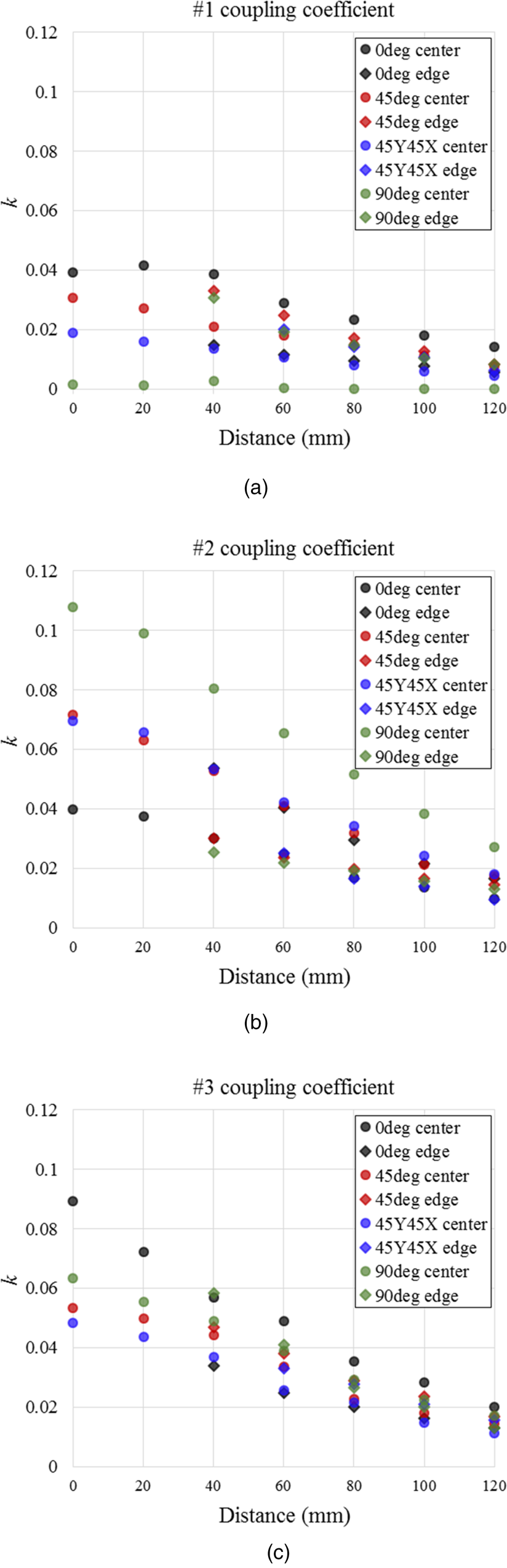
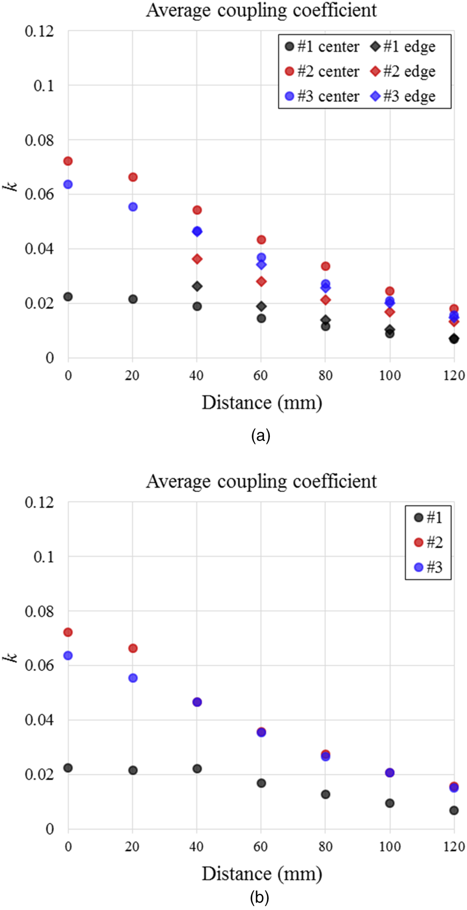
Figures 8(a), 8(b) and 8(c) show the coupling coefficient for using receiver #1, #2, and #3, respectively under several positions and angular orientations. The average k values of these three receiver coil structures are also calculated and plotted in Fig. 9. The following important observations should be noted:
• For #1, k is very close to zero when the coil is placed at the center of the transmitter coil at 90o, as the two coils are perpendicular (Fig. 8(a)). The low k value means that it is not suitable as a 3-D receiver for use with a planar transmitter coil. Nevertheless, #1 is included here as a reference case.
• For #2, the k is much higher than that of #1 for each distance, but the variation of k for any given distance between the centers of the transmitter and receiver coils is wider than the variation of k of #3. A wide variation of k for a given distance means that it is more sensitive to angular orientation (Fig. 8(b)).
• For #3, the variation of k for each distance is narrower than those of #1 and #2. This means that the k value stays within a small range for a given distance regardless of its angular orientations (Fig. 8(c)). The practical implication is that #3 offers a more consistent mutual coupling and therefore WPT capability with less sensitivity of the angular orientation.
• The average k plot in Fig. 9 shows that the average k for #2 and #3 is almost identical except when the distance is less than 20 mm (where #2 has a slightly higher k than #3). These results mean that both #2 and #3 are capable of functioning as a 3-D receiver when use with a 1-D transmitter coil. But #3 has less sensitivity than #2 in terms of angular orientation.
Measured coupling coefficients of receivers #1, #2, and #3 at different distances from the transmitter coil under different angular orientations, respectively.

Averaged mutual coupling coefficient of receivers #1, #2, and #3 at different distances from the transmitter coil under different angular orientations. (a) Averaged k of receivers at center or edge and (b) the averaged k over all positions.

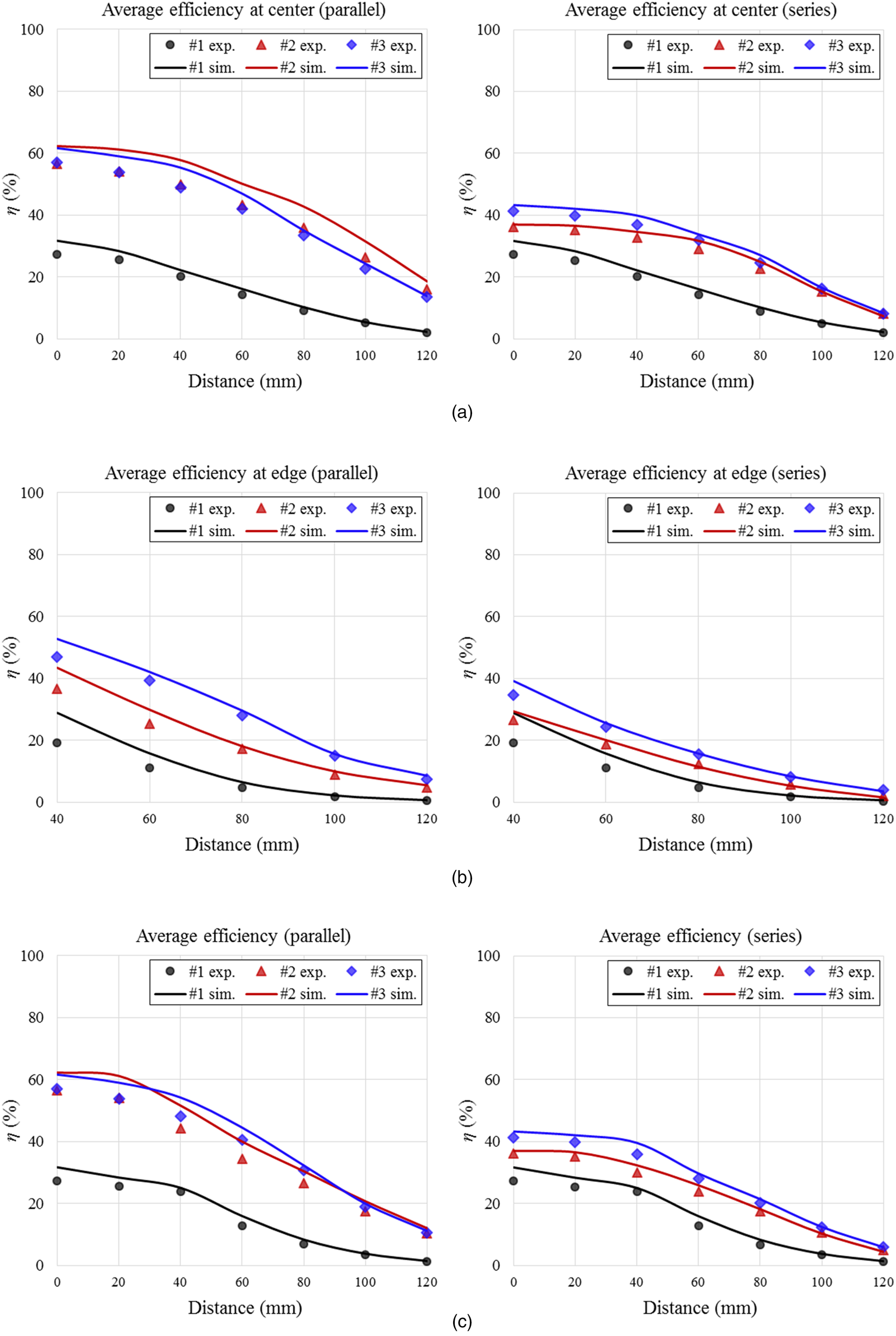
The average efficiencies η are calculated and shown in Fig. 10 which confirms that the two proposed multi-coil receivers #2 and #3 can achieve higher efficiencies than the ordinary single-coil receiver #1, whichever connecting manner (parallel or series-output) is used. It also indicates that when aligned at the center of the transmitter, #3 connected in parallel has a little lower averaged efficiency than #2, but in other three cases (center-series connection, edge-parallel connection, and edge-series connection), the average efficiencies of #3 are all obviously higher than #2, and the overall average efficiencies of #3, whether in parallel or series connection, are higher than that of #2. Figure 10 also shows that in most of the positions, the parallel-output connection has higher efficiencies than the series-output connection, for both receivers #2 and #3.
Averaged circuit efficiencies of using receivers #1, #2 and #3 at different distances from the transmitter coil under different angular orientations. (a) Averaged η at center, (b) averaged η at edge and (c) averaged η over all positions. The solid lines represent simulation values and the dots represent the measured values.

Generally, both receivers #2 and #3 can be used as a 3-D receiver, but receiver #3 has a more stable performance against position changes, and a higher averaged circuit efficiency. Besides, #3 uses less ferrite material, which results in less fabricating cost. Therefore, #3 has a better performance for omnidirectional WPT with a 1-D planar transmitter coil. For an output connection manner, the parallel method offers higher efficiencies.
Furthermore, some improvements of the proposed planar multi-coil receivers can be made in the future. Figure 7 indicates that the coils 1 and 2 of receiver #2 have similar coupling coefficients at all the eight cases, which means one of them can be removed to further reduce the thickness of receiver #2. Besides, the PCB wires can replace the litz wires and thinner ferrite plate can be used to reduce the thickness of the planar receivers.
6. Conclusions
This paper presents a comparative study on three “slim” receiver coil structures for use as a 3-D receiver with a planar transmitter coil. The mutual coefficient k is adopted as a performance indicator for comparison because it is directly related to the energy efficiency in WPT applications. Experimental results show that some receiver coil structures have wide variation of k under different angular orientations than the others. It is found that both (i) the magnitude of k and (ii) the variation of k under different angular orientations for a given distance are important factors in the comparison. In this particular study, receiver #1 is not suitable as a 3-D receiver. Both #2 and #3 can serve as a 3-D receiver because they have reasonably high k over the transmission distance, but #3 is less sensitive to angular orientations because its k value has the smallest variation range for a given distance.
Acknowledgment
This project is partially supported by the Hong Kong Research Grant Council under General Research Fund GRF project (17206715).
 Minxin Wu (S'16) received her B.Eng. degree in electrical engineering from Tsinghua University, Beijing, China in 2014. She is currently working toward her Ph.D. degree in the Department of Electrical and Electronic Engineering, The University of Hong Kong, Hong Kong. Her current research interests include magnetics design, wireless power transfer, and power electronics.
 Wenxing Zhong (M'13) received his B.Eng. degree in electrical engineering from Tsinghua University, China in 2007 and his Ph.D. degree from the City University of Hong Kong, Hong Kong in 2012. Currently, he is a professor in the Department of Electrical Engineering, Zhejiang University, China. From March 2016 to May 2017, he was a Research Assistant Professor in the Department of Electrical and Electronic Engineering, The University of Hong Kong, Hong Kong. His current research interests include wireless power transfer and power electronics. Since 2015, he has received two Transactions First Prize Paper Awards from IEEE Power Electronics Society. He was recruited by “the Thousand Young Talents Plan” of the Chinese central government in 2018.
 Siew Chong Tan (M'06–SM'11) received his B.Eng. (Hons) and M.Eng. degrees in electrical and computer engineering from the National University of Singapore, Singapore in 2000 and 2002, respectively, and his Ph.D. degree in electronic and information engineering from the Hong Kong Polytechnic University, Hong Kong in 2005. He is currently a Professor in the Department of Electrical and Electronic Engineering, The University of Hong Kong, Hong Kong. Prof. Tan was a Visiting Scholar at Grainger Center for Electric Machinery and Electromechanics, University of Illinois at Urbana-Champaign, Champaign, from September to October 2009, and an Invited Academic Visitor of the Huazhong University of Science and Technology, Wuhan, China, in December 2011. His research interests are focused on the areas of power electronics and control, LED lightings, smart grids, and clean energy technologies.
 S. Y. R. Hui (M'87–SM'94–F'03) received his B.Sc. (Eng.) Hons in electrical and electronic engineering from the University of Birmingham in 1984 and a D.I.C. and Ph.D. in electrical engineering from Imperial College London in 1987. Presently, he holds the Philip Wong Wilson Wong Chair Professorship at the University of Hong Kong and a Chair Professorship at Imperial College London. He has published over 260 refereed journal publications. Over 60 of his patents have been adopted by industry. His research interests include power electronics, wireless power, sustainable lighting, and smart grids. His inventions on wireless charging platform technology underpin key dimensions of Qi, the world's first wireless power standard, with freedom of positioning and localized charging features for wireless charging of consumer electronics. He has also developed photo-electro-thermal theory for LED systems. He has received the IEEE Rudolf Chope R&D Award and the IET Achievement Medal (The Crompton Medal) in 2010 and IEEE William E. Newell Power Electronics Award in 2015. He is a Fellow of the Australian Academy of Technological Sciences & Engineering (since 2010), US Academy of Inventors (since 2018), and the Royal Academy of Engineering, UK (since 2016).