I. INTRODUCTION
Among the different types of antenna arrays, planar antenna arrays play an important role in modern wireless communications and radar applications. For the design of planar arrays, one has to adequately choose the number of antennas in the array, their positions, and the feeding current (amplitude and phase) of the antenna elements. The reduction of the peak side lobe level (PSLL) can be accomplished by either using uniformly excited antenna elements and optimizing the elements positions, or by fixing the elements positions (e.g. uniformly distributed) and optimizing the feeding current of the antenna elements to be either turned ON (unity value) or turned OFF (zero value). The latter way is referred to as planar array thinning [Reference Haupt1–Reference du Plessis24]. Thinning targets not only reducing the side lobes levels, but it also decreases the manufacturing cost, hardware complexity, weight of antenna arrays, and power consumption. Another advantage for array thinning is the fact that the turned-ON elements can use any uniform weighting to have the same side lobe level. Recently, different well-known evolutionary algorithms; differential evolution (DE) [Reference Zhang, Jiao, Weng and Zhang12], genetic algorithm (GA) [Reference Haupt1–Reference Johnson and Rahmat-Samii3, Reference Hamici and Ismail5, Reference Jain and Mani9, Reference Zhang, Jiao, Chen and Li10, Reference Mahanti, Pathak and Mahanti14, Reference Oliveri and Massa17, Reference Chen, Yun, He and Han21, Reference Jain and Mani22, Reference du Plessis24], particle swarm optimization (PSO) [Reference Pathak, Mahanti, Singh, Mishra and Chakraborty13, Reference Wang, Feng and Liu15, Reference Li, Yang, Ouyang, Nie and Zhou23], pattern search algorithm [Reference Razavi and Forooraghi6], Bees algorithm [Reference Guney and Onay4], ant colony optimization [Reference Quevedo-Teruel and Rajo-Iglesias19], and biogeography-based optimization (BBO) [Reference Singh and Kamal18] have been applied in the synthesis of thinned antenna arrays.
In this paper, the newly proposed global optimization method, teaching–learning-based optimization (TLBO) [Reference Rao, Savsani and Vakharia25–Reference Niknam, Azizipanah-Abarghooee and Narimani33] is used to design thinned planar arrays of isotropic radiators with optimum side lobe level reduction and optimum number of turned-ON elements. TLBO is based on the teaching–learning process in any class which is between the teacher, who is the best informative one, and his/her students, and between the students themselves [Reference Rao, Savsani and Vakharia25, Reference Rao, Savsani and Vakharia26]. Compared to other evolutionary optimization techniques, TLBO has the advantage of being free of tuning parameters; one has only to choose the total number of iterations and the population (class) size. Recently, the TLBO has been successfully applied in mechanical design [Reference Rao and Savsani29], design of data clustering [Reference Satapathy and Naik30], and design of planar steel frames [Reference Toğan31] which proved the TLBO validity as a valuable optimization technique compared to other already developed optimization techniques. To our knowledge, the first application of the TLBO on the design of antenna arrays has appeared in [Reference Dib and Sharaqa34], where it was applied to the optimal design of thinned concentric circular antenna arrays.
The objectives of this paper are twofold: Firstly, to further introduce the TLBO method to the Electromagnetics community. Secondly, for the design of thinned planar arrays, it is shown that the TLBO method gives results that are better than (or as good as) those published in the literature which are obtained using other well-known evolutionary techniques. The rest of this paper is organized as follows: In Section II, TLBO is briefly described; the reader can consult [Reference Rao, Savsani and Vakharia25–Reference Niknam, Azizipanah-Abarghooee and Narimani33], and the references therein, for the full details of the TLBO algorithm. In Section III, the planar array geometry, the array factor and the used fitness functions are presented. Then, in Section IV, numerical results are given and compared with the results obtained using other optimization methods. Finally, the paper is concluded in Section V.
II. TEACHING–LEARNING-BASED OPTIMIZATION
TLBO is a newly proposed evolutionary global optimization method which was proposed by Rao, Savsani, and Vakharia to solve constrained optimization problems [Reference Rao, Savsani and Vakharia25–Reference Rao and Savsani29]. TLBO is inspired by the teaching–learning process which is between the teacher and his students, and between the students themselves. In the TLBO method, the students/learners in the class try to increase their knowledge from the best one in the population who is defined as the teacher. The design variables are analogous to the different courses taught to the learners, while the learners' grades are analogous to the “fitness function” value. The TLBO algorithm is divided into two phases: the “teacher phase” and the “learner phase”. In the teacher phase, the students learn directly from the teacher, whereas in the learner phase, the students gain knowledge by interacting with each other. For its implementation, TLBO requires only common controlling parameters such as population (class) size and number of generations (iterations). To apply the TLBO algorithm to any problem, the problem goes in three steps: creating a set of randomly chosen solutions/population to the problem, then applying teacher, and learner phases to reach the optimal solution.
A) Teacher phase
In this phase, the teacher tries his best to increase the average result (grades) of the class. Similar to other evolutionary optimization techniques, this phase starts by randomly creating a set of solutions (initial population) to the problem. In other words, the population X is randomly initialized by creating a matrix of N rows and D columns, where N is the population (class) size, and D is the dimension of the problem (i.e. the number of courses that are involved in the teaching/learning process). An individual X k (k = 1, … , N) within the population is a real-valued vector with D elements which represents a single possible solution to a particular optimization problem. In every iteration i (i = 1, … , Maxitr), each existing solution is updated according to the following expression:
 $$X_{j\comma k\comma i\; \left({new} \right)\; } = \; X_{j\comma k\comma i\; \lpar old\rpar } + \; \lpar Difference\_Mean\rpar _{j\comma k\comma i}\comma$$
where the mean difference is computed as follows:
 $$\lpar Difference\_\,Mean\rpar _{j\comma k\comma i} = \; r_i \; \lsqb X_{j\comma kbest\comma i} - \left({T_F } \right)\lpar M_{j\comma i} \rpar \rsqb .$$
In the above equations, M j,i is the mean result of the learners in a specific course j (j = 1, … , D), X j,kbest,i is the best learner (i.e. the teacher) in subject j (that is the one that resulted in the minimum value of the fitness function), T F is a teaching factor that decides the value of the mean to be used, and r i is a random number in the range [0, 1]. The value of T F can be either 1 or 2, which is computed randomly with equal probability as T F = round [1 + rand]. At the end of this phase, X j,k,i (new) is accepted if it gives a better (that is less) function value. All the accepted ones are kept and are used as the input to the next phase; the learner phase. The following pseudo-code summarizes the TLBO teacher phase:
Students.Temporary_Mark = Students.Mark (Create temporary matrix of population)
Students.Temporary_Result = Students.Result (Create temporary array of fitness values)
For i = 1 : N (Number of students)
Mean.Result = Mean(Students(i).Temporary_Mark) (Find the mean mark for each course)
TF = {1, 2} (Randomly choose 1 or 2)
Sort the population from best to worst
Teacher.Mark (Define the best solution as a teacher mark)
For k = 1 : D (Number of courses)
Student(i).Mark_New(k) = Students(i).Temporary_Mark (k) + ((Teacher.Mark(k) TF * Mean_Result(k))*Rand);
end
Student(i).Results_New (Calculate the new fitness function value)
If Students (i).Results_New (i)<Students(i).Result
Students(i).Mark = Student(i).Mark_New
Students(i).Temporary_Mark = Student(i).Mark_New
Students(i).Result = Student(i).Results_New
end
end
B) Learner phase
In this phase, the learners (students) increase their knowledge by interacting with each other. Of course, a learner tends to increase his/her knowledge by interacting with those who have more knowledge than him/her. Firstly, two different learners X j,P,i and X j,Q,i are randomly selected. Then, they are updated according to the following rule:
 $$\eqalign{X_{j\comma P\comma i\; \left({new} \right)\; } & = \; X_{j\comma P\comma i\; } + r_i \; \lpar X_{j\comma P\comma i} - X_{j\comma Q\comma i} \rpar \quad {\rm if}\quad X_{j\comma P\comma i} \, \, \; \cr & \quad {\rm gives}\, \, {\rm a}\, \, {\rm better}\, \, {\rm fitness}\, \, {\rm function}\, \, {\rm value}.}$$
 $$\eqalign{X_{j\comma P\comma i\; \left({new} \right)\; } & = \; X_{j\comma P\comma i\; } + r_i \; \lpar X_{j\comma Q\comma i} - X_{j\comma P\comma i} \rpar \quad {\rm if}\quad X_{j\comma Q\comma i} \; \, \, \cr & \quad {\rm gives}\, \, {\rm a}\, \, {\rm better}\, \, {\rm fitness}\, \, {\rm function}\, \, {\rm value} .}$$
The new solution is adopted if it gives a better (i.e. less) fitness function value. At the end of this phase, all accepted solutions are kept and used as an input to the teacher phase in the next iteration. The whole process ends when the number of iterations reaches a pre-chosen value for the maximum number of iterations. From the above, it is clear that one does not need to deal with any tuning parameters, other than the population size and maximum number of iterations. For interested readers, more details are available in [Reference Rao, Savsani and Vakharia25–Reference Rao and Savsani29]. The following pseudo-code summarizes the TLBO learner phase:
Students.Temporary_Mark = Students.Mark (Created temporary matrix of population)
Students.Temporary_Result = Students.Result (Created temporary arrays of fitness values)
For i = 1 : N (Number of students)
Choose a student R randomly
if Students(i).Result<Students(R).Result
for k = 1 : D (Number of courses)
Student(i).Mark_New(k) = Students(i).Mark(k) + ((Students(i).mark(k) - Students(R).Mark(k))*rand);
end
else
for k = 1 : D (Number of courses)
Student(i).Mark_New(k) = Students(i).mark(k) + ((Students(R).mark(k) - Students(i).mark(k))*rand)
end
end
Student(i).Results_New (Calculate the new fitness function value)
If Students(i).Results_New<Students(i).Result
Students(i).Mark = Student(i).Mark_New
Students(i).Temporary_Mark = Student(i).Mark_New
Students(i).result = Student(i).Results_New
end
end
III. GEOMETRY, ARRAY FACTOR AND FITNESS FUNCTION
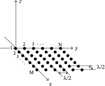
Figure 1 shows the geometry of an M × N planar antenna array with isotropic antenna elements lying in the x–y plane. In general, the radiation pattern of this array can be described by its array factor, which is given as follows:
 $$AF\left({I\comma \; \; \theta\comma \; \emptyset } \right)= \mathop \sum \limits_{m = 1}^M \mathop \sum \limits_{n = 1}^N I_{mn} \exp \; \lcub j\; k\; \lpar x_m \; u + y_n \; v\rpar \rcub \comma$$
where
 $$\eqalign{& k = \displaystyle{{2\pi } \over \lambda }\comma \; \; x_m = \lpar m - 1\rpar \; dx\comma \; \quad y_n = \lpar n - 1\rpar \; dy\comma \; \cr & \quad \quad u = \sin \theta \cos \emptyset\comma \; \quad v = \sin \theta \sin \emptyset.}$$
I mn represents the excitation amplitude of the (m, n)th element in the array, which is equal to unity if the (m, n)th element is turned ON, while it is zero if the element is turned OFF; dx and dy are the inter-element distances along the x- and y-axes, respectively. In this paper, these distances are taken to be half-wavelength (λ/2) at the design frequency.
Geometry of a planar antenna array with isotropic radiators.

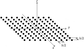
As a special case, Fig. 2 shows a symmetric 2M × 2N planar antenna array with isotropic antenna elements lying in the x–y plane. Assuming an inter-element distance of λ/2, the array factor for this array can be written as follows:
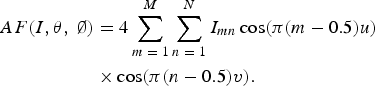 $$\eqalign{AF({I\comma \theta\comma \; \emptyset } )&= 4\mathop \sum \limits_{m\; =\; 1}^M \mathop \sum \limits_{n \;=\; 1}^N I_{mn} \cos \lpar \pi \lpar m - 0.5\rpar u\rpar \; \cr& \times \cos \lpar \pi \lpar n - 0.5\rpar v\rpar .}$$
For this symmetric planar array, the problem reduces to finding the amplitudes (0 or 1) of the elements lying in one quadrant only.
Geometry of a symmetric planar antenna array with isotropic radiators.

In antenna array problems, there are many parameters that can be used to evaluate the fitness (or cost) function such as gain, side lobe level, radiation pattern, and size. Here, the goal is to design thinned planar arrays with minimum PSLL in all ϕ planes. Thus, in the examples presented in this paper, the following fitness functions are considered:
 $$\hskip -25pt\left(1 \right)\quad F_1 = Minimize\, \lpar PSLL\lpar dB\rpar \rpar _{all\; \emptyset \; planes}\comma$$
 $$\eqalign{\left(2 \right)\quad F_2 & = Minimize\, \lsqb \lpar PSLL _o - \; PSLL_d \rpar ^2 \; H\left(X \right)\cr & \quad + \lpar T_o^{OFF} - T_d^{OFF} \rpar ^2 \; H\left(Y \right)\rsqb .}$$
In the above, the function F 1 minimizes the PSLL around the major lobe in all ϕ-planes without any constraint on the number of elements which are turned OFF. On the other hand, F 2 minimizes the PSLL in all ϕ-planes with a constraint on the desired number of turned-OFF elements, where PSLL o is the maximum PSLL during the optimization process, PSLL d is the desired maximum PSLL, T dOFF is the desired number of turned-OFF elements. Moreover, H(X) and H(Y) are the Heaviside step functions defined as follows:
 $$\eqalign{ & X = \; (PSLL_o - \; PSLL _d ),\; \; Y = (T_o^{OFF} - T_d^{OFF} ), \cr & [H\left( X \right),\; H\left( Y \right)]=\; \left\{ {\matrix{ {\left[ {1,\; 0} \right]\quad \; {\rm if}\quad X \geq 0,\; Y\gt 0} \cr {\left[ {0,\; 1} \right]\quad {\rm \; if}\quad X\lt 0,\; Y \leq 0} \cr } } \right\}.}$$
Thus, for the design of thinned planar arrays with minimum side lobe level, the optimization problem is to search for the current amplitudes (I mn's) that are turned ON or OFF that accomplish this.
IV. NUMERICAL RESULTS
A) Example 1: 6 × 6 planar array
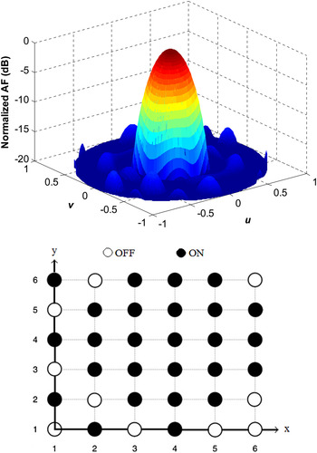
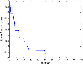
In this example, TLBO is used to optimize a 6 × 6 planar array (Fig. 1), which consists of 36 isotropic radiating elements (indicating that the dimension of the problem is 36). As indicated before, the inter-element distance is fixed, and equals to half-wavelength. The side lobes are suppressed in all ϕ-planes without any constraint on the number of turned-OFF elements; thus, equation (7) is used as a fitness function. The TLBO is run for 20 independent times, and the best result is shown in Fig. 3. This optimized thinned planar array has a PSLL of −16.71 dB in all ϕ-planes and its aperture has 10 OFF elements out of 36 ones. The same array was optimized in [Reference Zhang, Jiao, Weng and Zhang12] using the Boolean Differential Evolution (BDE) technique and the best array had only six OFF elements with a PSLL of −16.64 dB. Thus, TLBO results are better than the BDE ones in the sense of the obtained thinning factor, which is defined as the ratio between the number of OFF elements and the total number of elements. The TLBO configuration shown in Fig. 3 has a thinning factor of 27.8%, whereas the BDE results presented in [Reference Zhang, Jiao, Weng and Zhang12] have a thinning factor of 16.7%. In this example, the TLBO method outperforms BDE by obtaining almost the same PSLL with less number of turned ON elements. Figure 4 shows the convergence plot, which clearly shows that the result converges within 60 iterations only. It is worth mentioning that a class (population) size of 50 was used in this example.
Radiation pattern for the best 6 × 6 thinned planar array, and its geometry.

The convergence curve for the 6 × 6 array example using TLBO.

B) Example 2: 10 × 10 planar array
In this example, TLBO is used to optimize a 10 × 10 planar array (Fig. 1), which consists of 100 isotropic radiating elements. As in the previous example, the inter-element distance is fixed, and equals to half-wavelength at the design frequency. Equation (7) is used as a fitness function so that the side lobes are suppressed in all ϕ-planes without any constraint on the number of turned-OFF elements. The TLBO is run for 20 independent times; Fig. 5 shows the best result along with the array geometry. This optimized thinned planar array has a PSLL of −19.64 dB in all ϕ-planes and its aperture has 35 OFF elements out of 100 ones. The same array was optimized in [Reference Zhang, Jiao, Weng and Zhang12] using the BDE technique and the best array had only 24 OFF elements with a PSLL of −19.56 dB. Again, in this example, the TLBO method outperforms BDE by obtaining almost the same PSLL with less number of turned-ON elements. In this example, both the class (population) size and the “maximum number of iterations” were set to 100.
Radiation pattern for the best 10 × 10 thinned planar array, and its corresponding geometry.

C) Example 3: 20 × 10 symmetric planar array
In this example, TLBO is used to optimize a 20 × 10 symmetric planar array (Fig. 2), which consists of 200 isotropic radiating elements with a fixed inter-element distance of half-wavelength. Since the array is symmetric, the optimization problem reduces to obtaining the excitation amplitudes for the elements in one quadrant only. Thus, the number of variables is reduced to 50. To have a fair comparison with the results presented in [Reference Zhang, Jiao, Chen and Li10, Reference Zhang, Jiao, Weng and Zhang12, Reference Singh and Kamal18], the fitness function in equation (8) is used instead of equation (7). In each case, the desired number of turned-OFF elements T dOFF is set to be the same as the optimal array presented in [Reference Zhang, Jiao, Chen and Li10, Reference Zhang, Jiao, Weng and Zhang12, Reference Singh and Kamal18].
Using TLBO along with equation (8), the following results are obtained:
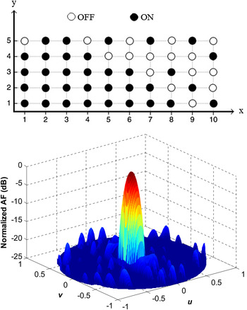
(1) A planar array with a thinning factor of 32% and PSLL of −20.4 dB. The geometry of this array is shown in Fig. 6, along with its corresponding pattern. Since this is a symmetric planar array, Fig. 6 shows the geometry in the first quadrant only. This array has the same thinning factor and PSLL as the BBO one presented in [Reference Singh and Kamal18]. Specifically, in [Reference Singh and Kamal18], using BBO, an optimal planar array with 32% thinning factor and PSLL of −20.42 dB was obtained.
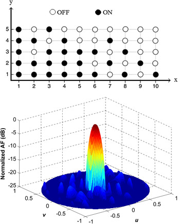
(2) A planar array with a thinning factor of 46% and PSLL of −20.54 dB. The geometry and the corresponding array factor of this array are shown in Fig. 7. This array has the same thinning factor and almost the same PSLL as the BDE one presented in [Reference Zhang, Jiao, Weng and Zhang12]. Specifically, in [Reference Zhang, Jiao, Weng and Zhang12], using BDE, an optimal planar array with 46% thinning factor and PSLL of −20.49 dB was obtained.
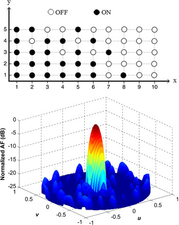
(3) A planar array with a thinning factor of 50% and PSLL of −20.15 dB. The geometry of this array is shown in Fig. 8, along with its corresponding pattern. This array has the same thinning factor as the one obtained using orthogonal genetic algorithm (OGA) [Reference Zhang, Jiao, Chen and Li10], with the PSLL reduced by 0.7 dB (−20.15 versus −19.44 dB).
Thus, again, TLBO yields results that are as good as (or better than) those obtained by other techniques. As in the previous example, both the class (population) size and the “maximum number of iterations” were set to 100.
Configuration of the optimized symmetric 20 × 10 array with a 32% thinning factor, and its corresponding radiation pattern.

Configuration of the optimized 20 × 10 array with a 46% thinning factor, and its corresponding radiation pattern.

Configuration of the optimized 20 × 10 array with a 50% thinning factor, and its corresponding radiation pattern.

V. CONCLUSIONS
In this paper, the newly proposed TLBO method was used in the optimal design of thinned planar antenna arrays to provide a radiation pattern with an optimum minimum side lobe level and number of turned-ON elements. Several examples were investigated, and the TLBO results were compared with those obtained using other optimization techniques. For the problem studied here, the TLBO (without any modifications) performed better than (or as good as) other optimization techniques, which clearly shows the effectiveness of the TLBO method. The TLBO has the advantage of being free of tuning parameters; one just needs to set the values of the population size and the maximum number of iterations.
 Nihad I. Dib obtained his B.Sc. and M.Sc. degrees in Electrical Engineering from Kuwait University in 1985 and 1987, respectively. He obtained his Ph.D. degree in Electrical Engineering (major in Electromagnetics) in 1992 from the University of Michigan, Ann Arbor. Then, he worked as an assistant research scientist in the Radiation Laboratory at the same school. In September 1995, he joined the Electrical Engineering Department at Jordan University of Science and Technology (JUST) as an Assistant Professor, and became a full Professor in August 2006. His research interests are in computational electromagnetics, antennas, and modeling of planar microwave circuits.