1 Introduction
To the best of our knowledge, Elliott (Reference Elliott1955) from Hughes Research and Development Laboratories, California, US, was the first to introduce the term ‘azimuthal surface waves’ (ASWs) to designate electromagnetic perturbations which propagate in cylindrical waveguide structures across the axis of symmetry along the azimuthal angle
 $\unicode[STIX]{x1D711}\propto \exp (\text{i}m\unicode[STIX]{x1D711}-\text{i}\unicode[STIX]{x1D714}t)$
. Here,
 $m$
is the azimuthal wavenumber (a natural number), and
 $\unicode[STIX]{x1D714}$
is the ASW’s angular frequency. In other words, these perturbations propagate with zero axial wave vector,
 $\boldsymbol{k}_{\Vert }=0$
. ‘Surface’ means, that the waves do not propagate in a homogeneous infinite medium and the presence of a boundary between media with different physical properties is required for their existence. This study was initiated by its potential application in the field of transmission lines and antennae.
The following metal–dielectric structure was under consideration (see figure 1). The internal space,
 $r<R_{1}$
, was occupied by a perfect conductor with inner radius
 $R_{1}$
with teeth which extend to the outer radius
 $R_{2}$
. The space between the teeth was assumed to be composed of a pure dielectric which could be air. The outer space,
 $r>R_{2}$
, was air. Neither a plasma nor a static magnetic field were applied. The theoretical predictions were approved by a coarse experiment.
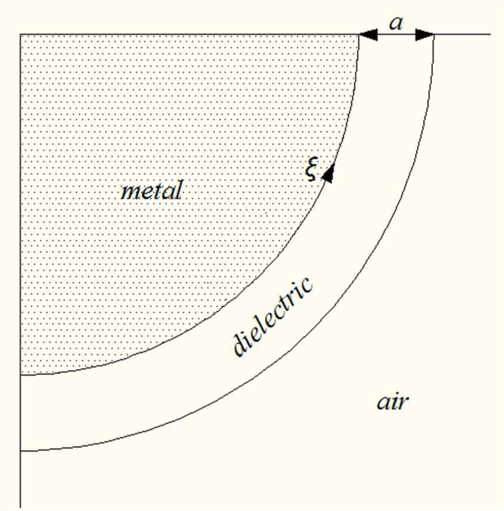
However, the first attempt to study surface wave propagation over a coated conductor with small cylindrical curvature in the direction of propagation was reported by Horiuchi (Reference Horiuchi1953) from the Laboratory of Communication Instruments, Tokyo, Japan. The outline of how to study the wave fields in this case was suggested on the basis of the system of plane conductors studied earlier. The schematic of the waveguide structure, perfect metal–dielectric–air, is given in figure 2. The width of the dielectric layer was assumed to be equal to
 $a$
. Again, the waveguide structure did not include a plasma or a static magnetic field. The spatial distribution of the surface wave fields was derived in the approximation of small curvature in the
 $\unicode[STIX]{x1D709}$
direction.
Wait (Reference Wait1965, Reference Wait1966) from the Central Radio Propagation Laboratory, National Bureau of Standards, Colorado, US, was the first to study ASWs in cylindrical plasma waveguide structures. The objective of the research was to give a possible explanation for the propagation of radio waves in the spherical Earth–ionosphere system. In the paper by Wait (Reference Wait1965), electromagnetic waves were studied in the following plasma–metal structure (see figure 3). An infinitely long circular metal cylinder (perfect conductor) with radius
 $R_{3}$
was immersed into the compressible plasma. A static magnetic field was neglected. It was concluded that, in the neighbourhood of the plasma interface, the field amplitude of the ASW can be comparable to, or are even much larger than, that of the radiating modes.
Schematic of the problem in the paper by Elliott (Reference Elliott1955).

Schematic of the problem in the paper by Horiuchi (Reference Horiuchi1953).

Schematic of the problem in the papers by Wait (Reference Wait1965, Reference Wait1966).

Anatoliy M. Kondaratenko from V. N. Karazin Kharkiv National University, Kharkiv, Ukraine, with co-authors was the first in the Soviet Union to study ASWs in cylindrical plasma–dielectric–metal structures both in the presence of a static axial magnetic field (Girka et al.
Reference Girka, Girka, Kondratenko and Tkachenko1988, Reference Girka, Girka, Kondratenko and Tkachenko1989a
) and without any magnetic field (Girka et al.
Reference Girka, Girka, Kondratenko and Tkachenko1989b
). The research was initiated by possible application in the area of plasma electronics. In these papers, the title ‘surface’ gained a new content to designate that the wave amplitude decreases when going from the plasma interface into the plasma core rather than oscillate, as it does in the case of volumetric waves. The following waveguide structure was under study (see figure 4). A homogeneous, cold, collisionless plasma column with radius
 $a$
was placed inside the metal chamber with radius
 $b$
. The space,
 $a<r<b$
, was filled by a dielectric with dielectric constant
 $\unicode[STIX]{x1D700}_{d}$
. The frequency ranges were determined within which the electromagnetic plasma perturbations had a surface nature. The spatial distribution of the ASW fields was studied, explicit expressions for the ASW eigenfrequencies in various limiting cases were derived and the dependencies of the ASW eigenfrequencies on the parameters of the plasma waveguide were studied numerically. Including the plasma insert makes it possible to control the dispersion properties of the electromagnetic waves via the plasma particle density, an external static magnetic field and the dimensions of both plasma column and dielectric layer. The advantages of application of ASWs for designing plasma electronic devices are as follows. The azimuthal direction of wave propagation makes it possible to design devices of plasma electronics with small axial size. The surface nature of ASWs makes it possible to reach a higher efficiency in producing and maintaining gas discharges (Girka, Girka & Pavlenko Reference Girka, Girka and Pavlenko2001). In addition, ASW excitation is possible by an electron beam gyrating around the plasma column along large Larmor orbits (Girka, Girka & Pavlenko Reference Girka, Girka and Pavlenko2011a
,Reference Girka, Girka and Pavlenko
b
; Girka, Girka et al.
Reference Girka, Girka, Morgal and Pavlenko2011). This possibility is explained by the absence of the need to produce a wave structure in the plasma core. The surface nature of ASWs makes it possible also to operate in the frequency range within which the plasma is non-transparent for electromagnetic waves.
Schematic of the problem in the papers by Girka et al. (Reference Girka, Girka, Kondratenko and Tkachenko1988, Reference Girka, Girka, Kondratenko and Tkachenko1989a ,Reference Girka, Girka, Kondratenko and Tkachenko b ).

If the metal waveguide is entirely filled with plasma, ASWs are unidirectional (Girka et al.
Reference Girka, Girka, Kondratenko and Tkachenko1989a
), i.e. in the definite frequency range ASWs propagate in the perfect direction (with perfect sign of azimuthal wavenumber). The plasma–metal structure considered by Girka et al. (Reference Girka, Girka, Kondratenko and Tkachenko1989a
) can be easily obtained from that presented in figure 4 by removing the dielectric layer (putting
 $a=b$
).
The surface nature of ASWs makes it possible to replace the internal space of the plasma column by some other medium. Nikolay A. Azarenkov from V. N. Karazin Kharkiv National University, Kharkiv, Ukraine, with co-authors proposed to place an internal perfect conductor into the structure studied by Girka et al. (Reference Girka, Girka, Kondratenko and Tkachenko1989a ). In this case, one deals with a coaxial plasma layer bordered by inner and outer perfect metal conductors (Azarenkov, Ostrikov & Shcherbinina Reference Azarenkov, Ostrikov and Shcherbinina1991; Azarenkov, Kondratenko & Ostrikov Reference Azarenkov, Kondratenko and Ostrikov1993). ASWs propagate in opposite directions along the opposite borders of the coaxial waveguide.
Schematic of the problem in the paper by Jazi & Mehdian (Reference Jazi and Mehdian2004).

B. Jazi from Shahid Beheshti University, and H. Mehdian from Tarbiat Moallem University, Tehran, Iran, proposed to introduce a dielectric rod along the axis of the waveguide structure as presented in figure 5. The dielectric rod occupied the space
 $r<R_{4}$
, the plasma layer was bordered on the vacuum layer at
 $r=a$
, the vacuum layer separated the plasma coaxial layer from the metal wall with radius
 $r=b$
. The structure was immersed into a constant axial magnetic field. The study was initiated by its possible application for rod dielectric Cherenkov plasma masers. The first part of the paper by Jazi & Mehdian (Reference Jazi and Mehdian2004) dealt with ordinarily polarized ASWs with the wave fields
 $B_{r}$
,
 $B_{\unicode[STIX]{x1D711}}$
,
 $E_{z}$
. The second part was devoted to studying the dispersion properties of extraordinarily polarized ASWs with the components
 $E_{r}$
,
 $E_{\unicode[STIX]{x1D711}}$
,
 $\text{B}_{z}$
– this part is wrong because of mistakes in the algebra when deriving the expressions for
 $E_{r}$
and
 $E_{\unicode[STIX]{x1D711}}$
from the set of Maxwell equations. The same mistakes are present in the papers by Shokri & Jazi (Reference Shokri and Jazi2003), Jazi & Shokri (Reference Jazi and Shokri2005), Jazi, Shokri & Arbab (Reference Jazi, Shokri and Arbab2006) and Daryanoosh & Mehdian (Reference Daryanoosh and Mehdian2007) and make these papers meaningless. The paper by Shokri & Jazi (Reference Shokri and Jazi2003) presented the limiting case of the paper by Jazi & Mehdian (Reference Jazi and Mehdian2004), the space
 $r<R_{4}$
was occupied there by a vacuum.
Comprehensive analysis of the dispersion properties of ASWs in plasma waveguides taking account of numerous experimental peculiarities such as an axial DC electric current, non-circularity of both boundaries, plasma–dielectric and dielectric–metal, toroidal and axial spatially periodic inhomogeneity of the static magnetic field was given in the monograph (Girka, Girka & Thumm Reference Girka, Girka and Thumm2014). Possible practical applications of ASWs in the sphere of plasma electronics, nanotechnologies and biomedical diagnostics were mentioned there.
Most results in papers by Girka et al. (Reference Girka, Girka, Kondratenko and Tkachenko1988, Reference Girka, Girka, Kondratenko and Tkachenko1989a
,Reference Girka, Girka, Kondratenko and Tkachenko
b
, Reference Girka, Girka and Pavlenko2001), Girka, Girka et al. (Reference Girka, Girka, Morgal and Pavlenko2011), Girka, Girka & Pavlenko (Reference Girka, Girka and Pavlenko2011a
,Reference Girka, Girka and Pavlenko
b
) are obtained for the case of a narrow dielectric gap which separates the plasma column from the metal wall,
 $b-a\ll a$
, and where the ASWs are of a volumetric nature. If the dielectric is assumed to be uniform, the electromagnetic fields of ASWs can be presented in the gap,
 $a<r<b$
, as a linear combination of Bessel functions of the first and second kind,
 $\text{J}_{m}(\unicode[STIX]{x1D709})$
and
 $\text{N}_{m}(\unicode[STIX]{x1D709})$
. In the case of the narrow gap, the wave radial change is small and the zeroth radial mode of ASWs is under the consideration. The advantage of the zeroth radial mode is as follows: the effect of plasma parameters on its dispersion properties is the most pronounced as compared to those of the higher radial modes. On the other hand, practical needs of electronics require higher frequencies and shorter wavelengths of electromagnetic radiation which can be provided by application of the higher radial modes of ASWs without any change in the waveguide design.
The dispersion properties of ASW higher radial modes in cylindrical plasma-filled metal waveguides without an external static magnetic field were studied in detail by Girka, Omelchenko & Sydora (Reference Girka, Omelchenko and Sydora2017). It was shown that the eigenfrequencies of higher radial modes of ASWs can reach the upper limit of the frequency range within which ASWs exist in contrast to those of the zeroth radial mode. Higher radial modes of ASWs can propagate in waveguides where the radius and plasma particle density are not very small.
The present paper is devoted to studying the dispersion properties of ASW higher radial modes in cylindrical plasma waveguides with an external axial static magnetic field. It generalizes the study of ASW dispersion properties carried out for the case of the zeroth radial mode (Girka et al. Reference Girka, Girka, Kondratenko and Tkachenko1988) in waveguides with an external axial static magnetic field to the case of higher radial modes, and that carried out by Girka et al. (Reference Girka, Omelchenko and Sydora2017) for plasma waveguides without an external static magnetic field to the case of a uniform static axial magnetic field.
The paper is arranged as follows. The procedure for deriving the dispersion relation and its analytical solution are given in § 2. Detailed numerical analysis of the dispersion relation is accomplished in § 3. Conclusions and discussion are summarized in the final § 4.
2 Derivation of the dispersion relation and its analytical study
Here the plasma–dielectric–metal waveguide structure presented in figure 4 is considered. The structure is assumed to be homogeneous in the axial direction,
 $\unicode[STIX]{x2202}/\unicode[STIX]{x2202}z=0$
in cylindrical coordinates.
Within the plasma space,
 $0<r<a$
, the electrodynamic properties of the medium are described by the permittivity tensor of a cold, collisionless plasma. Its two components, which are used here, are in the high-frequency limit as follows (Brambilla Reference Brambilla1998):
 $$\begin{eqnarray}\unicode[STIX]{x1D700}_{1}=1-\frac{\unicode[STIX]{x1D6FA}_{e}^{2}}{\unicode[STIX]{x1D714}^{2}-\unicode[STIX]{x1D714}_{e}^{2}},\quad \unicode[STIX]{x1D700}_{2}=-\frac{\unicode[STIX]{x1D6FA}_{e}^{2}\unicode[STIX]{x1D714}_{e}}{\unicode[STIX]{x1D714}(\unicode[STIX]{x1D714}^{2}-\unicode[STIX]{x1D714}_{e}^{2})}.\end{eqnarray}$$
In (2.1),
 $\unicode[STIX]{x1D6FA}_{e}$
is the Langmuir frequency and
 $\unicode[STIX]{x1D714}_{e}$
is the electron cyclotron frequency. The set of Maxwell equations can be reduced for extraordinarily polarized ASWs (whose components are
 $E_{r}$
,
 $E_{\unicode[STIX]{x1D711}}$
,
 $\text{B}_{z}$
) to the modified Bessel differential equation for the axial wave magnetic field
 $\text{B}_{z}$
. Its solution, which satisfies the boundary condition that the wave fields must be finite within the waveguide, in particular, at the waveguide axis,
 $r=0$
, is as follows:
 $$\begin{eqnarray}\text{B}_{z}=C_{1}\text{I}_{m}(k_{\bot }r).\end{eqnarray}$$
In (2.2),
 $\text{I}_{m}(k_{\bot }r)$
is the modified Bessel function (Abramowitz & Stegun Reference Abramowitz and Stegun1972),
 $k_{\bot }^{-1}$
is the depth of the ASW penetration into the plasma,
 $k_{\bot }^{2}=(\unicode[STIX]{x1D714}/c)^{2}\unicode[STIX]{x1D700}_{1}(\unicode[STIX]{x1D707}^{2}-1)>0$
,
 $\unicode[STIX]{x1D707}=\unicode[STIX]{x1D700}^{2}/\unicode[STIX]{x1D700}_{1}$
and
 $C_{1}$
is a constant of integration. One can find the frequency ranges within which the azimuthal electromagnetic waves are of a surface nature from the condition
 $k_{\bot }^{2}>0$
. One of these ranges contains the electron cyclotron frequency and is under study in this paper:
 $$\begin{eqnarray}\unicode[STIX]{x1D714}_{LH}<\unicode[STIX]{x1D714}<|\unicode[STIX]{x1D714}_{e}|,\quad |\unicode[STIX]{x1D714}_{e}|<\unicode[STIX]{x1D714}<\unicode[STIX]{x1D714}_{1}-|\unicode[STIX]{x1D714}_{e}|.\end{eqnarray}$$
Here
 $\unicode[STIX]{x1D714}_{LH}=(\unicode[STIX]{x1D6FA}_{i}^{-2}+(\unicode[STIX]{x1D714}_{i}|\unicode[STIX]{x1D714}_{e}|)^{-1})^{-1/2}$
is the lower-hybrid frequency (
 $\unicode[STIX]{x1D6FA}_{i}$
and
 $\unicode[STIX]{x1D714}_{i}$
are the plasma and cyclotron frequencies of ions, respectively), and
 $\unicode[STIX]{x1D714}_{1}=0.5|\unicode[STIX]{x1D714}_{e}|+\sqrt{\unicode[STIX]{x1D6FA}_{e}^{2}+\unicode[STIX]{x1D714}_{e}^{2}/4}$
is the cutoff frequency. The second frequency range is above the upper-hybrid frequency and is out of the scope of this paper. These frequency ranges were determined for the first time by Girka et al. (Reference Girka, Girka, Kondratenko and Tkachenko1988), and the same ranges were derived in the high-frequency limit by Jazi & Mehdian (Reference Jazi and Mehdian2004).
ASW electric fields are linked with the ASW axial magnetic field as follows:
 $$\begin{eqnarray}E_{r}=\frac{\unicode[STIX]{x1D714}}{ck_{\bot }^{2}}\left(\frac{\unicode[STIX]{x1D700}_{2}}{\unicode[STIX]{x1D700}_{1}}\frac{\text{d}\text{B}_{z}}{\text{d}r}+\frac{m}{r}\text{B}_{z}\right),\quad E_{\unicode[STIX]{x1D711}}=\text{i}\frac{\unicode[STIX]{x1D714}}{ck_{\bot }^{2}}\left(\frac{\text{d}\text{B}_{z}}{\text{d}r}+\frac{m}{r}\frac{\unicode[STIX]{x1D700}_{2}}{\unicode[STIX]{x1D700}_{1}}\text{B}_{z}\right).\end{eqnarray}$$
The expressions (2.4) were derived for the first time by Wait (Reference Wait1966). The wrong expressions for
 $E_{r}$
and
 $E_{\unicode[STIX]{x1D711}}$
in Shokri & Jazi (Reference Shokri and Jazi2003), Jazi & Mehdian (Reference Jazi and Mehdian2004), Jazi & Shokri (Reference Jazi and Shokri2005), Jazi et al. (Reference Jazi, Shokri and Arbab2006), Daryanoosh & Mehdian (Reference Daryanoosh and Mehdian2007) invalidate the conclusions therein.
Within the dielectric layer,
 $a<r<b$
, the set of Maxwell equations can be reduced to the Bessel differential equation for
 $\text{B}_{z}$
. Its solution, which satisfies the boundary condition of zero tangential wave electric field at the loss-free metal wall,
 $r=b$
, is as follows:
 $$\begin{eqnarray}\text{B}_{z}=C_{2}[\text{J}_{m}(\unicode[STIX]{x1D705}r)\text{N}_{m}^{\prime }(\unicode[STIX]{x1D705}b)-\text{J}_{m}^{\prime }(\unicode[STIX]{x1D705}b)\text{N}_{m}(\unicode[STIX]{x1D705}r)].\end{eqnarray}$$
In (2.5),
 $\text{J}_{m}(\unicode[STIX]{x1D705}r)$
and
 $\text{N}_{m}(\unicode[STIX]{x1D705}r)$
are Bessel functions of the first and second kind, respectively,
 $\unicode[STIX]{x1D705}^{2}=(\unicode[STIX]{x1D714}/c)^{2}\unicode[STIX]{x1D700}_{d}$
and
 $C_{2}$
is a constant of integration. The prime denotes the derivative with respect to the argument.
To derive the dispersion relation, one has to apply two more boundary conditions (see, e.g. Girka et al.
Reference Girka, Girka, Kondratenko and Tkachenko1988), they are the continuity of the tangential wave electric and magnetic fields
 $E_{\unicode[STIX]{x1D711}}$
and
 $\text{B}_{z}$
:
 $$\begin{eqnarray}\frac{k_{\bot }}{\unicode[STIX]{x1D705}}\frac{\text{J}_{m}^{\prime }(\unicode[STIX]{x1D705}a)\text{N}_{m}^{\prime }(\unicode[STIX]{x1D705}b)-\text{J}_{m}^{\prime }(\unicode[STIX]{x1D705}b)\text{N}_{m}^{\prime }(\unicode[STIX]{x1D705}a)}{\text{J}_{m}^{\prime }(\unicode[STIX]{x1D705}b)\text{N}_{m}(\unicode[STIX]{x1D705}a)-\text{J}_{m}(\unicode[STIX]{x1D705}a)\text{N}_{m}^{\prime }(\unicode[STIX]{x1D705}b)}=\frac{\text{I}_{m}^{\prime }(k_{\bot }a)}{\text{I}_{m}(k_{\bot }a)}+\frac{\unicode[STIX]{x1D707}m}{k_{\bot }a}.\end{eqnarray}$$
In the case of higher radial modes, one can use the asymptotic expansions for the cylindrical functions (Abramowitz & Stegun Reference Abramowitz and Stegun1972) and derive the following approximate expression for the eigenfrequency of the ASW
 $l$
th radial mode:
 $$\begin{eqnarray}\unicode[STIX]{x1D714}\approx \frac{\unicode[STIX]{x03C0}lc}{\sqrt{\unicode[STIX]{x1D700}_{d}}(b-a)}\left[1-\frac{m\unicode[STIX]{x1D707}c^{2}}{\unicode[STIX]{x1D6FA}_{e}^{2}a(b-a)}\right].\end{eqnarray}$$
Since
 $\unicode[STIX]{x1D707}<0$
within the frequency range (2.3a,b
) under consideration, a simple analytical analysis shows that the eigenfrequencies of ASWs with positive azimuthal wavenumbers are higher than those of ASWs with
 $m<0$
. The same relation is known for the zeroth radial mode (Girka et al.
Reference Girka, Girka, Kondratenko and Tkachenko1988). Splitting of the spectrum is more pronounced for ASWs with higher radial mode number
 $l$
and higher azimuthal mode number
 $|m|$
. Regardless of the smallness of the splitting, it is favourable for the problem of ASW excitation with an electron beam gyrating along large Larmor orbits around the plasma column in the structure shown in figure 4, in which the dielectric layer is replaced by a vacuum (Girka, Pavlenko & Thumm Reference Girka, Pavlenko and Thumm2018), since the direction of the electron gyration in the axial static magnetic field coincides with the direction of ASW propagation with azimuthal wavenumber
 $m>0$
. It is superfluous to say that the expression (2.7) coincides with that derived by Girka et al. (Reference Girka, Omelchenko and Sydora2017) for the case of isotropic plasma waveguides in the limit
 $|\unicode[STIX]{x1D714}_{e}|\rightarrow 0\,(\unicode[STIX]{x1D707}\rightarrow 0)$
.
Dependence of the ASW eigenfrequency versus
 $k_{ef}$
.
 $Z=5$
;
 $b/a=$
2;
 $\unicode[STIX]{x1D700}_{d}=4$
,
 $m=+2$
(solid lines),
 $m=-2$
(dashed lines),
 $l=0$
, 1, 2.

Dependence of the ASW eigenfrequency versus effective wavenumber.
 $Z=5$
,
 $b/a=2$
,
 $l=1$
,
 $\unicode[STIX]{x1D700}_{d}=4$
,
 $m=1$
, 2 (solid lines),
 $m=-1$
,
 $-2$
(dashed lines).

3 Numerical analysis of the dispersion relation
Here, the results of a numerical study of the dispersion relation (2.6) are presented. In figures 6–9, the eigenfrequency normalized to the electron cyclotron frequency,
 $\unicode[STIX]{x1D714}/|\unicode[STIX]{x1D714}_{e}|$
, is used as the ordinate axis. Figure 10 shows the effect of the external static magnetic field on the dispersion properties of ASWs. Their eigenfrequency normalized by the Langmuir frequency,
 $\unicode[STIX]{x1D714}/\unicode[STIX]{x1D6FA}_{e}$
, is used as the ordinate axis. When studying numerically the dispersion properties it is usual to plot lines of the dependence of eigenfrequency versus wave vector. In the case of ASWs, the magnitude of the characteristic wave vector is
 $|m|/a$
. In figures 6–10 this vector normalized to the skin depth
 $\unicode[STIX]{x1D6FF}=c/\unicode[STIX]{x1D6FA}_{e}$
,
 $k_{ef}=|m|\unicode[STIX]{x1D6FF}/a$
, is used as the abscissa axis. If not mentioned specifically, the following parameters of the plasma waveguide system are used for calculating the eigenfrequencies:
 $Z\equiv \unicode[STIX]{x1D6FA}_{e}/|\unicode[STIX]{x1D714}_{e}|=5$
;
 $b/a=2$
;
 $\unicode[STIX]{x1D700}_{d}=4$
(quartz). This set of parameters corresponds to the conditions of a moderate experimental university laboratory.
Dependence of the ASW eigenfrequency versus effective wavenumber.
 $Z=5$
;
 $\unicode[STIX]{x1D6E5}=0.5$
, 1, 1.5;
 $m=2$
;
 $l=1$
,
 $\unicode[STIX]{x1D700}_{d}=4$
.

Dependence of the ASW eigenfrequency versus effective wavenumber.
 $Z=5$
,
 $b/a=2$
,
 $l=1$
,
 $m=2$
,
 $\unicode[STIX]{x1D700}_{d}=1$
, 2, 3, 4.

The dependence of the eigenfrequencies of the first ASW radial modes (
 $l=0$
, 1, 2) with azimuthal wavenumbers
 $m=+2$
(solid lines),
 $-2$
(dashed lines) versus
 $k_{ef}$
for the mentioned above values of the plasma waveguide parameters is plotted in figure 6. The numbers indicate the radial wavenumber
 $l$
. The numerical analysis confirms the analytical result: the eigenfrequencies of higher radial modes are higher than those of the zeroth radial mode studied earlier in Girka et al. (Reference Girka, Girka, Kondratenko and Tkachenko1988). For example, for
 $k_{ef}=0.5$
, the ASW with the azimuthal wavenumber
 $m=+2$
has the following eigenfrequencies: for the zeroth radial mode,
 $l=0$
,
 $\unicode[STIX]{x1D714}=0.815|\unicode[STIX]{x1D714}_{e}|$
; for the first radial mode,
 $l=1$
,
 $\unicode[STIX]{x1D714}=1.844|\unicode[STIX]{x1D714}_{e}|$
; and for the second radial mode,
 $l=2$
,
 $\unicode[STIX]{x1D714}=3.392|\unicode[STIX]{x1D714}_{e}|$
. The latter is higher than that of the first radial mode by the factor of 1.84 while (2.7) predicts the factor 2.
Figure 7 shows the dependence of the ASW eigenfrequencies versus
 $k_{ef}$
for two absolute values of azimuthal wavenumber
 $m=1$
, 2. It demonstrates that eigenfrequencies of ASW higher radial modes decrease with an increasing absolute value of the azimuthal wavenumber
 $m$
. In this respect, the ASW higher radial modes differ from the zeroth radial modes for which the increase of the eigenfrequency with increasing
 $m$
is well known (Girka et al.
Reference Girka, Girka, Kondratenko and Tkachenko1988). The increase in frequency versus
 $k_{ef}$
for ASWs with smaller absolute values of the azimuthal wavenumber is sharper than for ASWs with larger absolute values of
 $m$
. The lines which correspond to ASWs with smaller
 $m$
reach the upper boundary of the frequency range (2.3) for smaller values of
 $k_{ef}$
. In other words, higher radial modes of ASWs with larger
 $|m|$
can propagate in waveguides with smaller plasma column radius and smaller plasma particle density.
Figure 8 presents the results of numerically studying the effect of the dielectric layer width
 $\unicode[STIX]{x1D6E5}$
on the dependence of ASW eigenfrequency versus
 $k_{ef}$
. The numbers indicate the value of
 $\unicode[STIX]{x1D6E5}$
. Equation (2.7) predicts that the ASW eigenfrequency depends on
 $\unicode[STIX]{x1D6E5}$
almost inversely proportionally. However, for
 $k_{ef}=0.5$
, the ASW eigenfrequency in the case of
 $\unicode[STIX]{x1D6E5}=0.5$
is
 $\unicode[STIX]{x1D714}=2.932|\unicode[STIX]{x1D714}_{e}|$
, which is, by a factor of 1.59 (instead of the theoretical prediction 2), larger than the ASW eigenfrequency in the case of
 $\unicode[STIX]{x1D6E5}=1.0$
,
 $\unicode[STIX]{x1D714}=1.844|\unicode[STIX]{x1D714}_{e}|$
, and by a factor of 2.04 (instead of the theoretical prediction 3) larger than the ASW eigenfrequency in the case of
 $\unicode[STIX]{x1D6E5}=1.5$
,
 $\unicode[STIX]{x1D714}=1.437|\unicode[STIX]{x1D714}_{e}|$
. Note that for the case of the zeroth ASW radial mode (Girka et al.
Reference Girka, Girka, Kondratenko and Tkachenko1988), the eigenfrequency increases with increasing
 $\unicode[STIX]{x1D6E5}$
ceteris paribus.
Dependence of the ASW eigenfrequency versus effective wavenumber.
 $Z=5$
(solid lines),
 $Z=8$
(dashed lines),
 $b/a=2$
,
 $m=1$
, 2, 3;
 $l=1$
,
 $\unicode[STIX]{x1D700}_{d}=4$
.

Figure 9 shows the results for the effect of the dielectric layer permittivity
 $\unicode[STIX]{x1D700}_{d}$
on the dependence of ASW eigenfrequencies with the effective wavenumber
 $k_{ef}$
. The numbers indicate the value of
 $\unicode[STIX]{x1D700}_{d}$
. One can see a monotonic decrease of the eigenfrequency with increasing permittivity. Equation (2.7) predicts that the ASW frequency in the case of
 $\unicode[STIX]{x1D700}_{d}=4$
ceteris paribus should be twice less than in the case of
 $\unicode[STIX]{x1D700}_{d}=1$
. Indeed, for
 $k_{ef}=0.5$
, the ASW eigenfrequency in the case of
 $\unicode[STIX]{x1D700}_{d}=1$
is
 $\unicode[STIX]{x1D714}=3.466|\unicode[STIX]{x1D714}_{e}|$
, and by a factor 1.88 larger than the ASW eigenfrequency in the case of
 $\unicode[STIX]{x1D700}_{d}=4$
,
 $\unicode[STIX]{x1D714}=1.844|\unicode[STIX]{x1D714}_{e}|$
. In the case of the zeroth radial mode, the decrease of the ASW eigenfrequency with increasing
 $\unicode[STIX]{x1D700}_{d}$
is less pronounced.
The effect of the external static axial magnetic field
 $B_{0}$
on the ASW eigenfrequency is examined in figure 10. The solid lines correspond to the case of stronger
 $B_{0}:Z=5$
; the dashed lines correspond to the weaker
 $B_{0}:Z=8$
. One can draw the following conclusions on the basis of the results presented in figure 10. Increasing
 $B_{0}$
causes an insignificant increase of the eigenfrequency of the ASW higher radial modes. The same qualitative dependence of the ASW eigenfrequency on
 $B_{0}$
is well known (keeping in mind the assumption
 $\unicode[STIX]{x1D6FA}_{e}>|\unicode[STIX]{x1D714}_{e}|$
in the frame of which the present research is done) for the case of the zeroth ASW radial mode (Girka et al.
Reference Girka, Girka, Kondratenko and Tkachenko1988) and follows from (2.7) as well.
4 Conclusions
This paper presents a comprehensive analysis of the dispersion properties of ASW higher radial modes. The dependence of the ASW eigenfrequency on the plasma waveguide parameters such as the dimensions of the plasma column and dielectric layer, plasma particle density, azimuthal wavenumber and dielectric permittivity is studied. The eigenfrequency
 $\unicode[STIX]{x1D714}$
of ASWs is shown to increase with decreasing dielectric layer width
 $(b-a)$
, absolute value of azimuthal wavenumber
 $|m|$
, dielectric permittivity
 $\unicode[STIX]{x1D700}_{d}$
and especially with increasing radial wavenumber
 $l$
. An increase of a static axial magnetic field
 $B_{0}$
causes an insignificant increase of
 $\unicode[STIX]{x1D714}$
. The dispersion properties of the ASW higher radial modes are compared to those of the ASW zeroth radial mode. Eigenfrequencies of ASWs with positive azimuthal wavenumbers,
 $m>0$
, are shown to be higher than those with negative
 $m:\unicode[STIX]{x1D714}(|m|)>\unicode[STIX]{x1D714}(-|m|)$
.
These results are of interest for the field of plasma electronics. Excitation of ASW higher radial modes by an electron flow gyrating in a static axial magnetic field around the plasma column along large Larmor orbits was studied in Girka et al. (Reference Girka, Pavlenko and Thumm2018). Advantages of utilization of ASWs with extraordinary polarization excited by the rotating electron beam, as compared to the volumetric electromagnetic waves propagating along the axis of cylindrical waveguides excited by a longitudinal electron beam, in devices of plasma electronics are indicated e.g. by Girka, Girka & Pavlenko (Reference Girka, Girka and Pavlenko2011a ,Reference Girka, Girka and Pavlenko b ), Girka et al. (Reference Girka, Pavlenko and Thumm2018). Both experimental and theoretical studies carried out at the University of Maryland on the production of high-power microwave radiation in cusp-injected, large-orbit devices were reviewed by Destler et al. (Reference Destler, Chojnacki, Hoeberling, Lawson, Singh and Striffler1988).
In the limit of a narrow depth of the ASW penetration into the plasma column,
 $k_{\bot }a\ll 1$
, the ASW dispersion properties do not depend on the properties of the matter placed near the waveguide axis. In this case, the presented results should coincide with the results for the dispersion properties of ASWs in a dielectrically lined slow-wave waveguide (Jazi & Mehdian Reference Jazi and Mehdian2004). Jazi & Mehdian (Reference Jazi and Mehdian2004) considered the increase of the number of solutions of the dispersion relation as one of the most significant results of their study.
No explanation for the physical reasons for the increase of the number of solutions of the dispersion relation was given by Jazi & Mehdian (Reference Jazi and Mehdian2004). However, the electrodynamics of plasma waveguides proposes two possible explanations for this phenomenon. First, an increase of the number of solutions of the dispersion relation for surface-type waves can be caused by introducing an additional interface, in particular, the interface ‘dielectric rod–plasma layer’ which was done in Jazi & Mehdian (Reference Jazi and Mehdian2004). Second, if one finds additional roots of the dispersion relation for the flute
 $(k_{z}=0)$
electromagnetic perturbation with given azimuthal wavenumber
 $m$
, this can indicate that these roots correspond to other (higher) radial modes. Propagation of just higher radial modes is discussed in the present study. Probably this second case took place in numerically solving the dispersion relation in Jazi & Mehdian (Reference Jazi and Mehdian2004). It is a pity that the mistakes in deriving the expressions for the components of the extraordinarily polarized ASW fields in Shokri & Jazi (Reference Shokri and Jazi2003), Jazi & Mehdian (Reference Jazi and Mehdian2004), Jazi & Shokri (Reference Jazi and Shokri2005), Jazi et al. (Reference Jazi, Shokri and Arbab2006), Daryanoosh & Mehdian (Reference Daryanoosh and Mehdian2007) require these authors to revise the results obtained therein.
Studying the ASW dispersion properties can be of interest also for nanophysics (Ostrikov, Neyts & Meyyappan Reference Ostrikov, Neyts and Meyyappan2013) and medical physics (Baieva, Ihalainen & Toppari Reference Baieva, Ihalainen and Toppari2013).