Introduction
In microwave medical imaging systems, the speed of system operation in the image processing stage is of great importance due to the reconstruction of the image from electromagnetic waves in the multi-static state. Additionally, these approaches require a large number of antennas for gathering sufficient backscattered fields to solve the inverse scattering problem, resulting in a major disadvantage of large acquisition time associated with these types of systems [Reference Fatwasauri and Rizkinia1, Reference Wang2]. Therefore, several signal-image processing methods have been proposed to estimate the properties of the wave-propagating medium [Reference Naghsh, Ghorbani and Amindavar3]. Adaptive methods of sparse signal processing have a dominant role in fast scanning mode. Sparse signal processing for detecting targets in microwave imaging system applications such as breast cancer and intracranial hemorrhage detections was investigated in [Reference Guo and Abbosh4, Reference Stevanovic, Scapaticci and Crocco5]. From the brain imaging point of view, the need for a rapid image reconstruction method is of particular importance in recent research due to emergency cases such as stroke or tumor detection [Reference Hadi, Alshebeili, Jamil and El-Samie FE6–Reference Khoshdel, Asefi, Ashraf and LoVetri9]. Despite the many advantages offered by CS, certain gap areas that need attention are still present in its implementation. Standard CS theory does not always properly exploit all of the a-priori knowledge available in imaging applications. Moreover, enforcing restricted isometry property condition upon scattered data is not a feasible option. Therefore, systems that can generate sparse data should be developed. Converting the scattered signal data into a sparse form is not always feasible, so systems that can generate sparse data are to be designed. Moreover, acquiring a priori knowledge about the target may not always be possible, so robust CS strategies that can work without any a priori data (e.g., color CS) are needed [Reference Naghsh, Ghorbani and Amindavar10]. In addition, frequency hopping is a technique that employs multiple frequencies for better reconstruction [Reference Anjit, Benny, Cherian and Palayyan11–Reference Rani, Dhok and Deshmukh13]. It overcomes the effect of non-linearity in the optimization procedure so that an algorithm does not get trapped in local minima as shown by Salucci et al. [Reference Oliveri, Salucci, Anselmi and Massa14]. An improvisation to the sequential implementation of the frequency hopping can be obtained through the multiresolution technique which can iteratively zoom on the detected region-of-interest to adaptively improve the resolution of the retrieved image. This process allows one to keep the number of pixels within the background region low, thus mitigating the occurrence of local minima in the cost function [Reference Zhang, Hong and Wu15–Reference Fatwasauri and Rizkinia17]. This paper focuses on improving the microwave brain image reconstruction technique based on a new method of compressive sensing (CS). First, a multi-layer brain phantom and an elliptical array of bowtie antennas are simulated in commercial software CST [18]. To increase the depth penetration of the wave, an appropriate matching medium is designed. After immersing antennas inside the proposed matching medium, the usable frequency of the proposed bow-tie antenna is progressed from 1 to 4 GHz. To suppress clutter and remove the skin effect, a hierarchical multi-stage calibration technique is applied to backscattered signals. Then, 2D images are reconstructed based on the confocal image reconstruction algorithm. After creating the image with complete data, adaptive signal processing methods will be used to create sparse signals. Finally, a CS process will be used to reconstruct the low-dimensional image using sparse signals obtained using the proposed method. The validity of the presented system and its target detection algorithm has been verified via simulation in examples.
The proposed microwave imaging setup with the antenna configuration
The proposed microwave head imaging schematic with sixteen UWB bowtie antennas is shown in Fig. 1. A multilayer phantom of the human head model is simulated in CST software as a region of interest and modeled by applying changes to the internal dielectric properties of the brain, damage or brain tumor inside the brain. All physical and electrical characteristic of the multi-layer head phantom are summarized in Table 1. By arranging the sixteen elements of the bowtie antennas in elliptical geometry around the tissues the simulated microwave imaging system is performed.
Schematic of the simulated microwave imaging system for brain tumor detection, in CST medium including the multi-layer structure of the designed head phantom and antenna’s positions.

Physical and electrical characteristics of the multi-layer brain phantom

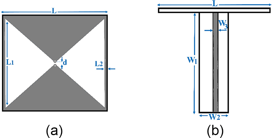
As shown in Fig. 2, a bawtie antenna is used to image the brain based on electromagnetic modality. Many reasons such as compact size, fixed phase point, as well as vertical feeding have made this type of antenna a good option for imaging the brain [Reference Wu, Liu and Zhu19, Reference Jalilvand, Vasanelli, Wu, Kowalewski and Zwick20]. The proposed antenna is a square radiating patch with a dipole placed inside the square loop, which creates a self-complementary structure that increases the impedance bandwidth. The basic antenna structure consists of a radiating patch, a vertical feed line. The radiating patch is printed on a Rogress 5880 substrate with the dimension of 22 × 22 mm2, the dielectric constant of 2.2, and the loss tangent of 0.001. Also, the proposed antenna is fed by a 50 Ω microstrip line with a variable length, and by optimizing this feed-line length, suitable impedance matching conditions have been obtained. All dimensions of the antenna are given in Table 2.
The proposed printed bowtie antenna with matching balun schematic: (a) radiating patch and (b) feed-line.

The proposed slot antenna dimensions

In electromagnetic based brain and breast imaging, due to the high permittivity of the human head environment and the skin effect, a high ratio of the radiation wave to the head does not penetrate in the biological model such as brain and breast [Reference Kaur and Kaur21, Reference Kaur and Kaur22]. Therefore, an appropriate matching medium is needed to be placed between the antenna and the head model to compensate this reflection. In order to decrease the mismatch effects between the antenna a coupling medium is designed based on a parametric sweep of its electrical characteristics. The simulation results show that by selecting 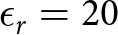 $\epsilon_r=20$ and σ = 0.5 S/m as electrical characteristics of the designed coupling medium, the optimum fit between the antenna and the head environment is achieved [Reference Ojaroudi, Bila and Salimi23]. In other words, after placing the antenna in this environment, in the presence of brain model the frequency bandwidth of the radiated wave is enhanced from 1 to 4 GHz. The six samples of the simulated transmission signals of the proposed antennas in different positions inside the designed matching medium are shown in Fig. 3. It can be seen from Fig. 3 that by determining a good choice for permittivity and conductivity of the matching medium all the sixteen antennas are radiated the required time-domain signals.
Simulated transmission signals of the proposed antennas inside the proposed matching medium.

In order to show the effectiveness of using matching medium structure in radiation characteristics of the proposed antenna, the E-field radiated from the two different antennas for two frequencies are displayed in Fig. 4. It can be seen that the using of appropriate matching medium in the proposed antenna has improved the radiative property, which has increased the penetration of the wave into the brain tissue. Also, due to the increasing in penetration depth, the field distribution is concentrated in the propagation path and the presence of the target is included in the scattered wave.
Simulated E-field pattern for different antenna: (a) antenna number 1 at 2 GHz, (b) antenna number 1 at 3.5 GHz, (c) antenna number 5 at 2 GHz, and (d) antenna number 5 at 3.5 GHz.

The confocal image reconstruction method
In this section, we took the raw images of the brain, which are formed by the aggregation of signals related to the transmission waves from the phantom of the brain, as input, and then we reached an improved state with transformations to reduce noise and increase the signal-to-clutter ratio. After simulating, the designed imaging setup all of the transmission signals are stored to reconstruct images in MATLAB. In the primary image extraction method, several steps are required to isolate the target response (tumor or damage) from the brain tissue, such as removing the skin effect, cross-linking the antennas, and estimating the permeability of healthy tissue, and so on. The beamforming algorithms for brain tumor detection is an easy and robust technique for tumor detection, which here we used two well-known beamformers which are delay and sum (DAS) and delay-multiply-and-sum (DMAS) for coherent signal integration to approximate the precise location of the tumor [Reference Fatwasauri and Rizkinia1–Reference Naghsh, Ghorbani and Amindavar3]. Then, using the confocal image processing method, the quality of the images is increased to extract the final range and shape of the target, which is a tumor. In addition, for effective permittivity from the point of the average dielectric constant of the multi-layer phantom 38.9 is considered in the proposed study case. In the confocal method, the final image is created by the coherent integration of the acquired signals’ energy at each focal point. Considering the M antenna in the multistatic framework, the energy relationship is defined as follows:
 \begin{equation}
I(r)=\int_{0}^{T_w}\left[\sum_{n=1}^{M}S_n(t-\tau_n(r))\right]^2dt,
\end{equation}
where Sn is the nth backscattered signal. To calculate this energy, the time delay associated with each focal point from all antennas must be calculated. These time delays are calculated as  $\tau_n(r)=(2d_n(r))/(vT_s)$, where
 $d_n(r)=|r-r_n |$ describes the discrete-time distance between the nth transmitting antenna rn and the focal point r, v describes the average velocity of signal propagation in brain medium, Tw is the window length, and Ts is the sampling interval. Due to reciprocity principle, instead of recording M2 signals, only
 $M (M -1)/2$ signals are required for the calculation of the energy profile. Through processing raw data, the 2D reconstructed images using the differential imaging scenario by subtracting a healthy brain image from the brain with tumor using DAS and DMAS beamformers are shown in Fig. 5. As illustrated in Fig. 5(b), the reconstructed image result using DMAS beamformer has a good resolution and contrast to determine the expected area of the hemorrhage tumor’s location.
Reconstructed image from confocal image reconstruction method with: (a) DAS beamforming and (b) DMAS beamforming.

The proposed compressive sensing method for ultra-fast microwave imaging
In this section, we propose a new approach for CS of the reconstructed images. Figure 6 shows the flowchart of the proposed CS as a post-processing stage in a microwave brain imaging algorithm. This automated CAD system could be further used for the reconstruction of images with different selected points. The reconstructed image in the confocal image reconstruction stage is the input for the proposed algorithm.
Flowchart of the proposed algorithm for tumor detection, based on compressive sensing.

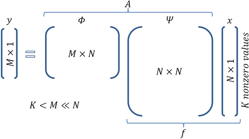
The post-processing CS section is implemented in MATLAB. CS is done based on the sparse signal generations of the acquired signals. First sparse signals are generated by using the random dictionary and Gaussian measurement matrices. For inverse matrix calculation, the Moore-Penrose Pseudoinverse which is based on singular value decomposition is considered. The next step is CS reconstruction. For this purpose, the dictionary and measurement matrices are reused in each pixel [Reference Ojaroudi, Bila and Salimi23]. Figure 7 demonstrates the basic equation of CS y = Ax and the corresponding dimensionality. It is actually a combination of the equation is 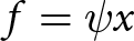 $f=\psi x$ (sparse representation of signal f) and
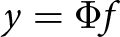 $y =\Phi f$ (sampling of signal f).
Matrix operations in compressed sensing.

In order to explain the CS basic principles, assuming that the length of a signal x is N × 1. If the signal is sparse with the factor of K, it can be represented as:
 \begin{equation}
x=\psi s,
\end{equation}
where ψ is an orthogonal and complete dictionary matrix. CS uses the linear operation of measurement matrix (Ψ) and the input signal as follow:
 \begin{equation}
y=\Phi x.
\end{equation}
This theory is based on the assumption that the measurement matrix Ψ is incoherent with the dictionary matrix ψ. By this condition the vector-matrix, s, can be reconstructed from  $G=O(K.LogN_t)$. In order to solve this equation the following convex optimization problem is required to be solved [18]:
 \begin{equation}
min(||s||_{l1}~~~\textrm{subject to}~y=\Phi \psi s).
\end{equation}
In this study, L1-Norm based convex optimization is proposed for solving this equation. As shown in Fig. 6, matrix operations in compressed sensing can be written as follow:
 \begin{equation}
y=\Phi \Psi s=As,
\end{equation}
which Φ is a random Gaussian measurement matrix and Ψ is the discrete cosine transform (DCT) matrix.
 \begin{equation}
A=\Phi \Psi.
\end{equation}
As abovementioned, the compressive method is first applied to generate the sparse signals. Then, from these sparse signals, images are obtained from the confocal image reconstruction method. Figure 7 shows six selected samples of the main signals along with the sparse samples of the same signals. As shown in Fig. 8, in the middle frequency range where the changes of the main signals are small, the number of selected samples in the sparse sample also includes a more significant reduction. In other words, an optimal sparsity is applied in such a way that less non-zero elements are used in the range where there are no signal changes. In order to show the potential capability of the CS method, the reconstructed image by using sparse signal is shown in Fig. 9. As can be seen from the result of image reconstruction with the CS method, unrealistic targets have also appeared in the image, which is due to the zeroing of some elements in the thinned signals, which has caused coherence in the formation of the beam. But the intensity of these goals is not enough to be confused with the main goal, in other words, this problem can be easily solved with an adaptive threshold. On the other hand, due to the sparsing of the input signals to the confocal program, the processing time has been improved by 45%, which reveals the major advantage of applying the CS method in detecting brain tumor.
Sparse signal generation based on compressive: (a) differential scattering parameters and (b) sparsed signals.

Reconstructed image from confocal image reconstruction method using sparse signals.

In the second stage of compression we used it in image level. For this purpose, we have applied the CS algorithm to the image matrix which contains 5500 pixels. The proposed CS algorithm obtains an average of 1000 random measurements of a 5500-pixel image. In this case, the vector of sparsing coefficients “s” is equal to K = 5, assuming that the image in the DCT domain has a sparse display (not very sparse in practice). Therefore, the original image can be retrieved from its compressed form using basic pursuit method. For the image recovery, the MATLAB toolbox l 1-MAGIC is used. This toolbox recovers the sparse signals via convex programming, where: x is original signal 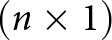 $(n\times 1)$, y is compressed signal
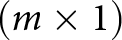 $(m\times 1)$, Φ is measurement matrix
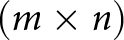 $(m\times n)$, Ψ is Basis functions
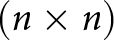 $(n\times n)$, s is sparse coefficient vector (to be determined)
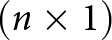 $(n\times 1)$, and
 $A=\Phi \Psi(m\times n)$. By inverting the matrix equation
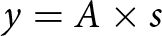 $y=A\times s$ and therefore recover s. S is a k-sparse linear combination of basis functions contained in Ψ. Note also that
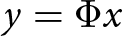 $y=\Phi x$. The main goal in image reconstruction is completely recovering s from y. Considering that the application method is an online method and that in this dissertation the compact sensor method is applied to both the return signal from the antenna ports and the reconstructed image. This method is based on an inversion of the matrix created with the measurement matrix and the matrix of basic functions, which ultimately leads to convex optimization, which by solving this optimization problem using the soft method
 $L1$, the ability to thin the signal and image. The extracted simulation results show the potential efficiency of the proposed method in matrix thinning and compact sensors. In order to apply the CS method in image level, after generating sparse signals and creating an image based on these signals, in order to perform the calculations of the relevant matrices, the pseudo-opposite Moore-Penrose operation is used for inversion. In other words, it is a matrix that can act as a partial alternative to the inverse matrix in cases where it is not possible to calculate the inverse matrix directly. According to this method, for each matrix A, there is only one matrix B so that it has the same dimensions as A, so pinv (A) is a costly method for calculating inv (A). If A is not a square matrix, or is square and singular, then inv (A) does not exist. In these cases, pinv (A) has some (but not all) properties of inv (A) [Reference Wu, Zhang, Chen and Yu24].
After inverse calculation of the matrix, the soft program  $L1$ is implemented to solve the equation under the condition of minimization. The problem of convex optimization is to find the value of at least one convex function (or at most one concave function) among convex sets. The most important advantage of this type of optimization problem is that each local optimal point is also a global optimal point, and any optimization algorithm that finds a local optimal point actually finds a global optimal point. In mathematics and related disciplines, norm is used in cases where the elements are limited to positive values [Reference An, Wang and Hoorfar25]. Suppose that p-norm is defined as follows:
 \begin{equation}
||x||_p=(\sum_{i=1}^{n}|x_i|^p)^{1/p}.
\end{equation}
If the value of p is 2, the resulting norm is called the Euclidean norm. To minimize this convex problem, the following optimizer condition is used:
 \begin{equation}
min x||x|| ~~~~~~~s.t~Ax=b,
\end{equation}
 \begin{equation}
x_p=L1_{eqpd}(x_0,A,A_t,b,P_{dtol},P_{dmax_i},C_{gtol},C_{gmax_i}).
\end{equation}
In this relation, x 0 is the starting point which is a vector N × 1, A is the set to the function that takes an N vector and returns a vector K or a matrix K × N. If A is a function, the algorithm works in “large” mode, solving Newtonian systems through the Conjugate Gradients algorithm. At is a function that takes a vector K and returns a vector N. If A is a matrix K × N, At is not ignored. b is the vector K × 1 of the observations.  $P_{(dtol)}$ is the tolerance for the dual-initial algorithm (the algorithm terminates if the duality gap is less than
 $P_{(dtol)}$. In this study default is 1e-3 for
 $P_{(dtol)}$ and
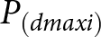 $P_{(dmaxi)}$ is the maximum number of initial and duplicate repetitions and the default is 50. Cgtolis the conjugate gradient tolerance and the default value is 1e−8. Cgmaxi is the maximum number of iterations for a conjugate gradient and the default is 200. In the next step, this method was applied to images created by the confocal method.
Figure 10 shows the reconstructed images based on two least squares and the pursuit basis inversion methods in CS for two scenarios of using 500 and 1000 pixels. As shown in Fig. 10(b) using 1000 pixels in pursuit basis inversion method is able to recover the tumor information.
The reconstructed images are based on two least squares and the pursuit basis inversion methods in compressive sensing for two scenarios of using (a) 500 and (b) 1000 pixels, (i) original image, (ii) compressed image, and (iii) reconstructed image.

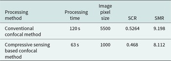
Table 3 shows the comparison of processing parameters in two modes without and using CS method. Other post-processing parameters from the comparison of the two images are given in Table 3.
The comparison of processing parameters with and without applying the compressive sensing method

Conclusion
In this paper, first, a UWB microwave imaging system is presented to detect and locate the tumor in a multi-layer human head phantom using the time-domain data. Then, the confocal method using DAS and DMAS beamforming is used for image reconstruction. In the next step, we have developed a novel post-processing method including CS in two levels. First to accelerate the speed of image reconstruction algorithm, and second to decrease the reconstructed image. Both methods were able to detect the tumor. The simulated results show by using the proposed CS method the image reconstruction processing time decreased to 63% and the sparse processing reconstructions had reduced dimension equal to 25% size of the original image. The results show that the developed imaging system has a good ability in detecting tumors in a biological medium, even small targets of a few centimeters.

Tavangar Najafi received his BTech degree in electrical engineering from University of Sistan and Baluchestan, Zahedan, Iran, in 1994 and MTech degree in electrical engineering in electrical engineering from Islamic Azad University of Bushehr, Bushehr, Iran, in 2008. He is currently pursuing his PhD at the Department of electrical engineering, Islamic Azad University, Shiraz Branch, Shiraz, Iran. His areas of interest include microwave imaging systems, antenna design, and signal processing. E-mail: najafit@yahoo.com

S.A. Emamghorashi received his BTech degree in electrical engineering from Shiraz University, Shiraz, Iran, in 1998 and MTech degree in communications engineering, field and wave from Amirkabir University of Technology (Tehran Polytechnic), Tehran, Iran, in 2001. He received his PhD in electromagnetic and antenna from Shiraz University, Shiraz, Iran, in 2017. From 2013 to 2018, he worked as a research assistant in the field of propagation, electromagnetic, and antenna, at Shiraz University Laboratory, Shiraz, Iran. He has published more than 20 referable papers in international journals and conferences. Since 2001, he is working as a faculty member of Islamic Azad University, Fasa Branch, Shiraz, Iran. His current interests include numerical techniques in electromagnetic, antenna, propagation, nano-antennas, neural networks, antenna optimization, and radar systems. E-mail: Aemamghorashi@iaufasa.ac.ir

Azar Mahmoodzadeh received her BTech degree in electrical engineering from Shiraz University, Shiraz, Iran, in 2005 and MTech degree in electrical engineering from University of Shahed, Tehran, Iran, in 2008. She received her PhD degree in electrical engineering from University of Yazd, Yazd, Iran in 2013. Her research interests include pattern recognition and image and signal processing. E-mail: Azarmahmoodzade@iaufasa.ac.ir