I. INTRODUCTION
The worldwide demand for electrical energy has been increasing steadily. The consumption of conventional fuels, such as coal, oil, and gas in thermal power plants, is rapidly increasing thereby depleting the fossil resources. For energy sustainability and economic reasons, residual fuel oil can be used along with coal in electricity generation using the conventional thermal systems, such as furnaces, boilers, and turbine components. Coal is an attractive fuel owing to its low price linked to its worldwide availability and anticipated future shortage of other fossil fuel reserves, such as oil and gas. But the combustion of coal generates corrosive gases near the superheater tubes. Reference Sidhu, Prakash and Agrawal1 The high resistance of high-chromium, nickel–chromium alloys to high-temperature oxidation and corrosion makes them widely used for welded and thermally sprayed coatings in fossil fuel-fired boilers. Reference Bala, Singh and Prakash2
The surface degradation of metal containment walls and heat exchanger tubes by combined erosion–corrosion (E–C) mechanism has been experienced in certain boilers, particularly fluidized bed combustors. Reference Levy3 Hot corrosion became a topic of importance and popular interest in the late 1960s as the phenomenon had been observed frequently on the high temperature components of coal conversion system. Reference Zheng, Maicang and Jianxin4 Metallic components in coal-gasification plants are exposed to severe corrosive atmospheres and high temperatures, the corrosive nature of the gaseous environments (i.e., environments containing O, S, and C) may cause rapid material degradation and result in the premature failure of components. Reference Sidhu and Prakash5 Detonation-gun (D-gun) is capable of producing the highest pressure, velocity, and density in the gas flow, which is not achievable by all other spraying techniques; as a result, the detonation coatings are characterized by extremely high density, low oxide content, high bond strength, high impact velocity, and low porosity. Reference Kamal, Jayaganthan and Prakash6 The aim of the present study is to evaluate the hot corrosion behavior of D-gun sprayed Cr3C2–NiCr, NiCrAlY + 0.4 wt% CeO2, and NiCoCrAlYTa on an iron-based superalloy in an actual industrial environment of a coal-fired boiler.
II. EXPERIMENTAL PROCEDURE
A. Substrate materials
Fe-based superalloy namely superfer 800H has been selected as the substrate material in the present study. Superfer 800H is widely used in the thermal power plants for the boiler tube steels. The alloy was procured from Mishra Dhatu Nigam Limited, Hyderabad (India) in the rolled sheet form, for protecting them against high temperature corrosive environment applications. The nominal chemical compositions of these alloys are given in Table I.
Chemical composition (wt%) for various superalloys.

B. Feedstock materials for the coatings
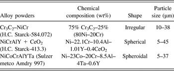
Three types of commercially available alloy powders namely Cr3C2–NiCr, NiCrAlY, and NiCoCrAlYTa produced by H.C. Starck, H.C. Starck-413.3 and Sulzer metco, respectively, were chosen for spray deposition using D-gun on the iron-based substrates. The chemical composition and particle size of all the alloy powders are given in Table II.
Composition of the alloy powders, shape, and size of the particles.

C. Deposition of the coatings
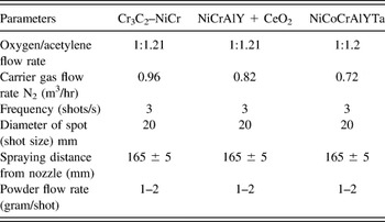
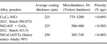
The D-gun was used to apply coatings on the superalloys at SVX Powder M Surface Engineering Pvt. Ltd, New Delhi (India). Standard spray parameters were designed at the above firm for deposition of the powders in the present work. All the process parameters, including the spray distance (165 ± 2 mm), were kept constant throughout the coating process. The process parameters for the spray process used for applying the coatings are summarized in Table III. Details regarding characterization of the coatings are explained in Refs. Reference Kamal, Jayaganthan and Prakash6–Reference Kamal, Jayaganthan and Prakash8. The average thickness, porosity, and microhardness values of the coatings are given in Table IV.
Spray parameters as used during D-gun spraying.

Feedstock powders; coating thickness, microhardness and porosity.

D. High temperature hot corrosion studies in coal-fired industrial boiler environment
The bare and the three D-gun coated specimens were exposed to the flue gases in the platen super-heater zone of the coal-fired boiler of Stage-II at Guru Nanak Dev Thermal Plant, Bathinda, Punjab, India. The zone was selected for the present study as many breakdowns occurred in the power plant due to hot corrosion. A hole of 1.2 mm diameter was drilled in all the specimens to hang them in the super-heater zone for experimentation. The coated specimens as well as bare specimens were polished with 1.0 μm alumina powder using cloth polishing wheel machine to obtain uniform surface for all the specimens. The physical dimensions of the specimens were measured with a Sylvac digital vernier caliper (Swiss make, resolution 0.001), to evaluate the thickness. The average of 10 measurements taken at different locations is reported as a thickness of each specimen before exposing them to the boiler environment.
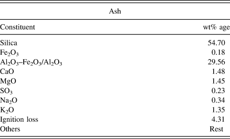
The specimens were then hanged with the help of a stainless steel wire through the soot blower dummy points at 27 m height from the base of the boiler. The specimens were exposed to the combustion environment for 10 cycles. Each cycle consisted of 100 h heating followed by 1 h cooling under atmospheric conditions. The temperature was measured at regular intervals during the study and the average temperature was about 900 °C with variation of ±10 °C. The chemical analysis of the ash present inside the boiler is given in Table V.
Chemical analysis of ash.

At the end of each cycle, the specimens were visually observed for any change in the surface texture, further it was washed by acetone. The weight of the specimens was measured subsequently using an Electronic Balance manufactured by Contech, Model CB-120 Mumbai, India, of sensitivity 0.001 g. The average volumetric flow rate of flue gases was approximately 122 m3/s. The values of SO x and NO x in the flue gases are estimated to be 280.53 mg/m3 and 1166.67 μg/m3, respectively. The constituents CO2 and O2 of the flue gas were determined to be 12 and 7%, respectively.
III. RESULTS AND DISCUSSION
A. Visual examination
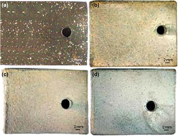
The macrographs for the bare and three coated specimens after 1000 h of exposure are shown in Fig. 1. Light gray colored scale appeared on the surface of bare substrate after the first cycle, which lasted up to the third cycle. The deposition of ash on the surface commenced after the fourth cycle. At the end of 10 cycles, white, green, and brown protrusions appeared on the surface with no spallation and cracks in the scale which can be observed from Fig. 1(a). The macrographs of the three coated specimens after exposure in the boiler are shown through Figs. 1(b)–1(d).
Macrographs of the (a) bare and D-gun sprayed, (b) Cr3C2–NiCr, (c) NiCrAlY + 0.4 wt% CeO2, and (d) NiCoCrAlYTa coated on superfer 800H after 1000 h exposure to low temperature super-heater zone of the boiler at 900 °C.

The macrograph of Cr3C2–NiCr coated specimen shows the formation of gray color scale after first cycle, which lasted up to the second cycle. After the third cycle, the deposition of ash was noticed which turned brown in the subsequent cycle. The surface was gray in color with brown patches at the end of 10 cycles which can be observed from Fig. 1(b).
In the case of NiCrAlY + 0.4 wt% CeO2 coated specimen, the color of the scale was initially light gray which turned dark with increase in the exposure time, observed till the end of the fourth cycle. The deposition of ash was observed after the fifth cycle. The formation of light brown color commenced after the fifth cycle which continued till the end of the 10th cycle as can be observed in Fig. 1(c). Even after 1000 h of exposure, the scale was intact and did not show any presence of cracks.
In the case of NiCoCrAlYTa coated substrate, light gray color was observed after first cycle. No spallation was observed during the course of the study. Deposition of ash was noticed after the fourth cycle. Later, the color turned dark gray which sustained till the 10th cycle as can be observed from Fig. 1(d).
B. Corrosion kinetics
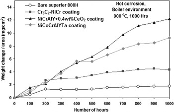
The change in the weight of the specimen with exposed duration in boiler environment for the bare and coated surfaces is determined. The scale formation is due to chemical reaction and partial oxidation of the coating elements like Cr, Al, and Ce at the nickel-rich splat boundaries. The oxidized coating remained intact and adhered to the substrate as shown in Figs. 2 and 3, providing protection from the boiler environment.
Weight change versus time plots for the bare and D-gun coated superfer 800H subjected to 1000 h cyclic exposure to low temperature super-heater zone of the coal-fired boiler at 900 °C.

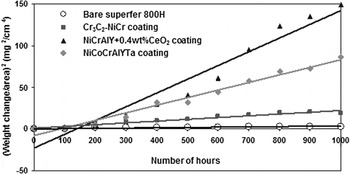
(Weight gain/area)2 versus number of hours plots for the bare and D-gun coated superfer 800H subjected to 1000 h cyclic exposure to low temperature super-heater zone of the coal-fired boiler at 900 °C.

The lowest weight gain observed with the bare specimen is due to the erosion of substrate and oxide scale spallation. Among the three coated specimens, substrate coated with Cr3C2–NiCr showed the lowest weight gain, which is lower than NiCrAlY + 0.4 wt% CeO2 by 65% and NiCoCrAlYTa by 54%. The change in the weight of the specimens with the duration of exposure is shown in Fig. 3. It is observed that all the coated and bare specimens follow the parabolic rate law, except NiCrAlY + 0.4 wt% CeO2 coated specimen. The parabolic rate constants for the bare and Cr3C2–NiCr, NiCrAlY + 0.4 wt% CeO2 and NiCoCrAlYTa coated specimens were estimated at 0.86, 8.1, 46 and 25, respectively.
C. Average scale thickness and depth of internal attack
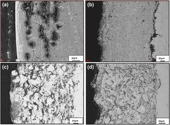
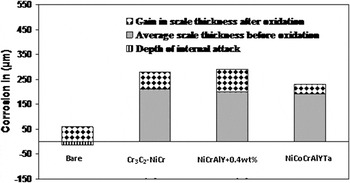
The back scattered electron (BSE) images for the cross-section of the scales formed on bare and coated specimens are shown in Fig. 4. The average scale thickness of the bare specimen is determined as 15 μm, and that for Cr3C2–NiCr, NiCrAlY + 0.4 wt% CeO2, and NiCoCrAlYTa coated superalloys are 220, 200, and 190 μm, respectively. The internal corrosion attack is absent in the case of coated superalloy, whereas the bare superalloy showed complete internal corrosion for up to 45 μm from the scale–substrate interface as shown in Fig. 5. The average gain in scale thickness is about 60, 70, 90, and 40 µm for the bare, Cr3C2–NiCr, NiCrAlY + 0.4 wt% CeO2, and NiCoCrAlYTa specimens, respectively, shown in Fig. 5.
BSE images for the bare and D-gun coated superfer 800H after 1000 h exposure to low temperature super-heater zone of the coal-fired boiler at 900 °C: (a) Bare superalloy (b) Cr3C2–NiCr coated (c) NiCrAlY + 0.4 wt% CeO2 coated (d) NiCoCrAlYTa coated.

Bar charts indicating the extent of corrosion for the bare and D-gun coated superfer 800H after 1000 h exposure to the coal-fired boiler at 900 °C.

D. X-ray diffraction analysis
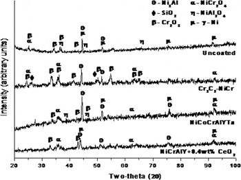
The x-ray diffraction patterns for the bare and coated specimens after exposure to the boiler environment for 1000 h are shown in Fig. 6. The surface of the bare and NiCoCrAlYTa coated specimens indicated the presence of NiCr2O4, Cr2O3, NiAl2O4, Ni3Al, and γ-Ni. In the case of Cr3C2–NiCr coated specimen, the scale on the surface indicated the presence of NiCr2O4, Cr2O3, SiO2, and Ni3Al. The NiCrAlY + 0.4 wt% CeO2 coated specimen indicated the presence of NiCr2O4, Cr2O3, Ni3Al, and γ-Ni phases.
X-ray diffraction patterns for the (i) bare and D-gun sprayed (ii) Cr3C2–NiCr (iii) NiCrAlY + 0.4 wt% CeO2 (iv) NiCoCrAlYTa coatings on superfer 800H after 1000 h of exposure to low temperature super-heater zone of the coal-fired boiler at 900 °C.

E. FESEM/EDS analysis
1. Surface analysis
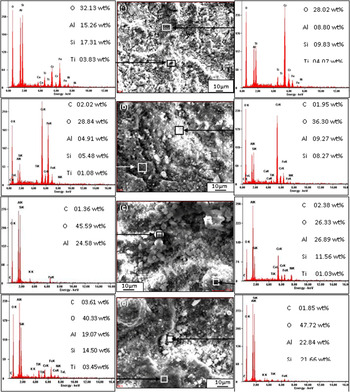
The field emission scanning electronic microscrope (FESEM) micrographs of the surface morphology after scale formation on the bare and coated specimens after exposure for 1000 h are shown in Fig. 7. The oxide scale formed on the bare specimen represents two regions consisting of bright and dark regions. The dark area on the surface indicates the formation of oxides of chromium, aluminum, silicon, and iron as shown in Fig. 7(a). The energy dispersed spectroscopy (EDS) analysis indicates the presence of SiO2, Al2O3, Cr2O3, and Fe2O3 with traces of TiO2, CaO, and NiO in the bright region. It can be inferred from the analysis that the composition of the bright region is analogous to ash composition along with certain other oxides in the scale.
FESEM/EDS analysis showing elemental composition (wt%) for the bare and D-gun coated superfer 800H after 1000 h exposure to low temperature super heater zone of the coal-fired boiler at 900 °C: (a) bare superfer 800H (b) Cr3C2–NiCr coated (c) NiCrAlY + 0.4 wt% CeO2 coated (d) NiCoCrAlYTa coated.

In case of Cr3C2–NiCr coated specimen as shown in Fig. 7(b), the adherence of the scale was uniform on the surface in the dark region, which is rich in chromium and iron followed by silica and aluminum. The presence of chromium, aluminum, and silicon was detected in the bright region as the major elements with traces of Fe, Ti, Ni, and Ca.
The scale formed on the surface of NiCrAlY + 0.4 wt% CeO2 coated specimen is shown in Fig. 7(c). A large number of globular white phase consisting mainly of alumina and silica indicating the deposition of ash on the surface can be observed. The EDS analysis of dull gray globular regions on the surface indicates the presence of ash deposition along with oxides of aluminum, nickel, chromium, and silicon. The presence of Ti in the scale indicates its outward diffusion from the substrate. The presence of Fe on the surface scale is due to diffusion from the substrate and partly due to interaction with ash.
The scale formed on the surface of NiCoCrAlYTa coated specimen as shown in Fig. 7(d) depicts the presence of uneven surface with the clusters of ash formation as white globules. EDS analysis of the dull region reveals the presence of O, Al, Si, and Fe. The white globules represent the ash deposition which contains oxides of Al and Si.
2. Cross-section analysis
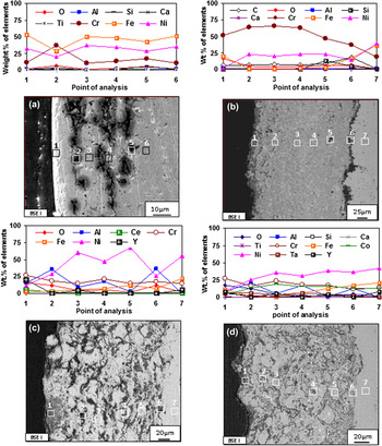
EDS analysis and back scattered electron image (BSEI) images at certain selected locations of interest in the cross-section of bare and coated specimens are shown in Fig. 8. Discontinuous oxide scale formation on the bare specimen can be observed from Fig. 8(a). The top surface of the scale consists mainly of iron, nickel, and chromium. In the subscale region in a plane parallel to the top, the scale has certain cracks in the dark region denoted by point 2 consisting of chromium oxide as evident from the EDS analysis. The location denoted by point 3, 4, and 5 depicts the presence of nickel, iron, and chromium. Point 6 shows the basic element of the substrate. BSEI image of the Cr3C2–NiCr coated specimen is shown as Fig. 8(b) which indicates the adherence of oxide scale on the surface of the coating depicted as point 1 in Fig. 8(b), the coating is rich with Cr and Ni.
Oxide scale morphologies and variations of elemental composition (wt%) across the cross-section of (a) bare and D-gun sprayed (b) Cr3C2–NiCr, (c) NiCrAlY + 0.4 wt% CeO2 and (d) NiCoCrAlYTa coating on superfer 800H after 1000 h exposure to the coal-fired boiler at 900 °C.

Along the coating–substrate interface shown as point 6 in Fig. 8(c), the amount of Fe and C increases while Cr and Ni decreases. EDS analysis at point 7 in the substrate indicates the absence of oxygen. The cross-sectional BSEI images of NiCrAlY + 0.4 wt% CeO2 coated specimen shown in Fig. 8(c) display the formation of scale at the top layer with oxygen, chromium, aluminum, and yttrium suggesting the formation of respective oxides and spinels. EDS analysis at point 2 indicates the formation of oxide of Al and Cr along the splat boundaries of nickel. Light gray regions (point 3 and 5) in the coating show nickel-rich splats with small quantities of Al, Fe, and Cr, absence of oxygen at these points suggests that these nickel-rich splats are in un-oxidized state. Half penny shaped regions in the coating (point 4) distributed along the splat boundaries depicts the presence of Al and Cr, where Ni decreases substantially. The dark region referred as point 6 in Fig. 8(c) is rich in aluminum and chromium along with oxygen thereby suggesting the formation of Al2O3 and Cr2O3. The absence of oxygen in the substrate indicated as point 7 in Fig. 8(c) shows that the coating has prevented the penetration of oxygen.
The oxide scale formed on the surface of NiCoCrAlYTa coated specimen consisting of oxides of Cr, Fe, and Y is shown as Fig. 8(d). Oxygen, chromium, and aluminum along the Ni-rich splat boundaries (at point 2 and 4) represent the formation of oxides stringers of Al and Cr. Ni-rich splats shown as point 3 and 5 in the coating are in un-oxidized state as oxygen is absent. The air entrapped during D-gun deposition was protected in the porosities, since the cooling of coating was rapid. There is lack of time for the remaining air to react with the surrounding coating alloys. However, the coating took in situ reaction during high temperature (900 °C) oxidation and formed alumina (Al2O3) at the splat boundaries and within open pores. During subsequent cycles, the formation of oxides has choked-up the pores, splat boundaries, and acted as diffusion barrier to the inward diffusion of corrosive species. This leads to Ni in the subscale region in an un-oxidized state. At the interface of substrate and coat shown as point 6 in Fig. 8(d), the concentration of iron and aluminum increases, whereas chromium decreases. Point 7 in the substrate shows the absence of oxygen indicating the protective behavior of the coating.
F. X-ray mapping analysis
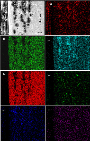
BSEI images and elemental x-ray mapping of the bare and coated specimens after 1000 h of exposure to low temperature of 900 °C in a coal-fired boiler are shown through Figs. 9–12. The BSEI images of the top layer of the scale for a bare specimen indicate the presence of iron, nickel, chromium as shown in Fig. 9. In the subscale region, the scale has cracked exposing the formation of Cr2O3 and SiO2 as evident from the oxygen distribution. During the course of study, oxygen might have penetrated deep into the substrate along the cracks of weak oxide scale. The image indicates the existence of oxygen, chromium, and silicon with a trace of Al and Ti in the dark region, where other elements have depleted.
Composition image (BSEI) and x-ray mappings across the cross-section of bare superfer 800H after 1000 h of exposure to low temperature super heater zone of the coal-fired boiler at 900 °C.

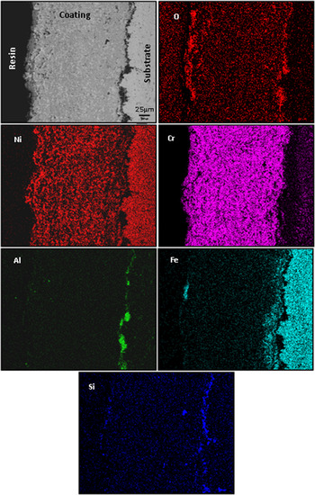
Composition image (BSEI) and x-ray mappings across the cross-section of D-gun sprayed Cr3C2–NiCr coated superfer 800H after 1000 h of exposure to low temperature super heater zone of the coal-fired boiler at 900 °C.

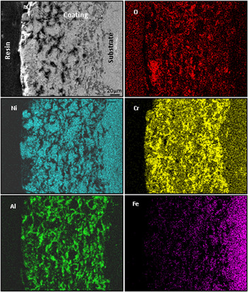
Composition image (BSEI) and x-ray mappings across the cross-section of D-gun sprayed NiCrAlY + 0.4 wt% CeO2 coated superfer 800H after 1000 h of exposure to low temperature super heater zone of the coal-fired boiler at 900 °C.

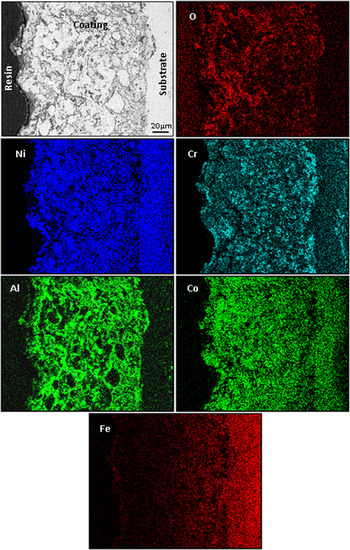
Composition image (BSEI) and x-ray mappings across the cross-section of D-gun sprayed NiCoCrAlYTa coated superfer 800H after 1000 h of exposure to low temperature super heater zone of the coal-fired boiler at 900 °C.

Elemental x-ray mapping analysis of the scale formed on the Cr3C2–NiCr coated specimen is continuous and has adhered on the surface without cracks as shown in Fig. 10. The top layer of the scale is enriched with oxides of Ni, Fe, Si, Al, and Cr. In the subscale region, the coating has Ni-rich splats which are un-oxidized, whereas Cr has partially oxidized. Aluminum and silicon oxide are detected at the coating–substrate interface with Si diffusing to the top layers of the coat during the initial cycles. The entrapped alumina particles retained in the asperities during grit blasting of the substrate, prior to deposition of the coatings, can be the reason. Another possibility of aluminum detection at the interface can be due to diffusion of iron with the formation of a band above the coating–substrate interface. Traces of iron in the top layer of the scale indicate its diffusion behavior from the substrate to the coating.
The NiCrAlY + 0.4 wt% CeO2 coated specimen forms a discontinuous and adherent oxide scale after exposure to boiler environment for 1000 h at 900 °C as shown in Fig. 11. The scale consists of oxides of Cr and Al distributed randomly. The coating has irregular shaped splats rich in Ni in the subscale region in an un-oxidized state. Al and Cr are detected along the splat boundaries with the existence of oxygen. Iron has shown its diffusion behavior into the coating material.
Elemental x-ray mapping analysis for the scale formed on the NiCoCrAlYTa coated specimen as shown in Fig. 12 after 1000 h of exposure to the boiler environment. The image shows the top layer of the oxide scale to contain O, Ni, Cr, Fe, and Al. A layer below it, the coating has un-reacted Ni- and Co-rich splats, whereas Cr and Al have oxidized and distributed along these splat boundaries, as evident from the oxygen distribution. The top layer of the scale has traces of iron which indicates its diffusion behavior from the substrate to the coating. Cobalt has diffused into the substrate and formed a thick band below the coating–substrate interface. Cr and Al have segregated along the coating–substrate interface, where Ni and Co have depleted.
IV. DISCUSSION
The lower weight gain of the bare specimen in comparison to the coated may be attributed to spallation along with erosion of the oxide scale. The common deposit found on boiler super heaters is sodium vanadyl vanadate, Na2O, V2O4, 5V2O5 which melts at a relatively low temperature of 550 °C. Above the melting point, the ash corrodes the metal due to longer contact period. Reference Sidhu and Prakash9 The accumulation of low melting point salts from flue gas on the fire tubes induces hot corrosion and is considered as the root cause for the severe damage of tube material of super heaters and re-heaters in thermal power plants. Reference Sidhu, Prakash and Agrawal10
The interaction of ash which consists of Na2O and K2O with gaseous SO2, SO3, O2, etc. results in the formation of alkali sulfates (K2SO4, Na2SO4). The alkali sulfates react with iron oxides present in the scale or ash, in the presence of SO3 form alkali-ion trisulphates (Na, K)3Fe(SO4)3. The alkali-iron tri-sulphates are molten in nature forming Na3Fe (SO4)3 at 624 °C, K3Fe(SO4)3 at 618 °C and mixed compound (Na, K)3Fe(SO4)3 at 552 °C. Reference Srivastava, Godiwalla and Banerjee11,Reference Weulersse-Mouterat, Moulin, Billard and Pierotti12 These molten compounds can flux the scale or react with the alloy to form internal sulphides. Hence, the alkali-iron trisulphides are responsible for the degradation of super-heater tubes in the coal-fired plant.
A. Bare specimen
The scale formed on the top surface of a bare specimen contains oxides of Cr, Fe, Al, Si, and Ti as evident from the EDS analysis as shown in Fig. 7. A significant quantity of Al and Si is determined in the ash. The formation of a thin oxide scale with subsequent depletion by spallation and erosion under cyclic heating and cooling might have created vertical cracks. The cracks which propagated parallel to the top surface might be responsible for the penetration of the corrosive species. The corrosion attack is estimated to be over a depth of 45 μm from the scale–substrate interface as shown in Fig. 5.
Depth of internal attack is taken as the distance from the scale–substrate interface up to which corrosive species have penetrated into the substrate. An average gain in scale thickness reported to be of 53 µm is due to deposition of ash. The XRD analysis presented as Fig. 6 for the bare specimen did not indicate the presence of the sulphide in the oxide scale due to the formation of very thin oxide scale on the surface of the substrate. Weulersse-Mouturat et al. Reference Weulersse-Mouterat, Moulin, Billard and Pierotti12 reported that due to their low content, alkali-iron-trisulphates are not detected in the scale. In general, bare samples follow a parabolic rate law, as can be inferred from the square of weight change (mg2/cm4) versus number of cycle plots shown in Fig. 3. Surface EDS analysis of the scale in the dark region revealed the presence of Cr, Al, Fe, and Si oxides as shown in Fig. 7(a).
B. Coated specimens
The maximum corrosion resistance with Cr3C2–NiCr coated specimen has been attributed to the formation of thin and continuous chromium oxide rich scale as can be observed from Fig. 4(b). The coating is in intimate contact with the substrate as evident from the BSEI micrograph. The chromium exhibits higher affinity for oxygen to form Cr2O3 during the earlier stages of oxidation, which acts as a diffusion barrier for the corrosive species to penetrate as reported by Bala et al. Reference Bala, Singh, Prakash and Karthikeyan13
The formation of chromium oxide fills intermolecular voids preventing the passage of oxygen further inside. These oxides, once formed, plug/seal the splat boundaries and all other possible diffusion paths in the coatings, thereby blocking or slowing the penetration of aggressive species. The surface of coated specimen after 1000 h of exposure shows the formation of thin oxide scale consisting mainly of Cr, Al, Si, Ni, and Fe as shown in Fig. 10. This is supported by the cross-sectional EDS as shown in Fig. 8(b). This would relatively reduce the weight gain and result in the steady state oxidation behavior even for prolonged exposure to high temperature.
The formation of small amounts of Fe2O3 on the top scale indicated by cross-section EDAX analysis [Fig. 8(b)] and supported by x-ray mapping results (Fig. 10) may be due to their diffusion from the substrate during earlier cycles of hot corrosion, was also noticed by Kamal et al. Reference Kamal, Jayaganthan and Prakash14 and Sundararajan et al. Reference Sundararajan, Kuroda, Nishida, Itagaki and Abe15 Iron has diffused to the coating–substrate interface by forming a band due to concentration difference. The presence of aluminum oxide at the coating–substrate interface may be due to grit blasting or diffusion from the substrate or from the ash or in a combination as shown in Fig. 10 which is in conformity with the results of the cross-sectional EDS analysis shown as Fig. 8(b).
The NiCrAlY + 0.4 wt% CeO2 coated specimen indicates the formation of discontinuous oxide scale [Fig. 4(c)] on the top surface consisting of O, Ni, Cr, Al, and Fe. The subscale region contains the oxides of Cr and Al along the un-oxidized Ni-rich splat boundaries. This suggested partial oxidation of the coating as revealed by cross-sectional EDS analysis [Fig. 8(c)]. The formation of these oxides is supported by x-ray mapping (Fig. 11). The presence of oxygen in the coating might be attributed to the penetration of certain oxidizing species through the irregular oxide scales formed at the top surface, open pores, and along the splat boundaries of the coating during the initial period of exposure. Once the oxides formed at the place of open pores, they plug/seal the splat boundaries and all other possible diffusion paths in the coatings, thereby blocking or slowing the penetration of aggressive species, further growth of the oxides becomes limited mainly to the specimens surface. This would relatively minimize the weight gain and result in the steady state oxidation behavior with prolonged exposure to high temperature. Similar findings have been reported by Belzunce et al. (2001) Reference Belzunce, Higuera and Poveda16 who have observed internal oxidation during the earlier stages of the study and suggested the penetration of oxidizing species into the coatings through the open pores until all the accessible internal surfaces got oxidized. Niranatlumpong et al. Reference Niranatlumpong, Ponton and Evans17 also opined that internal oxidation takes place due to porosity in the thermal spray coatings. Addition of CeO2 into the coating leads to grain refinement and purification of the grain boundaries thereby it reduces hot corrosion. Zhang and Li Reference Zhang and Li18 investigated the protective role of cerium added aluminide coating on mild steel and reported that cerium has improved the protective efficiency of the coatings against dry sand erosion and corrosion in dilute NaCl and H2SO4 environment.
The corrosion resistance with NiCrAlY + 0.4 wt% CeO2 coating is lower in comparison to Cr3C2–NiCr coating. This can be due to the formation of NiO which is less protective than Cr2O3 and ash deposition on the surface [Fig. 7(c)] which has permitted the penetration of corrosive species through the scale into the coating. The NiO formed in the surface scale is porous due to re-precipitation by fluxing action. The oxygen has penetrated deeply into the coating as the scale formed on the surface is nonuniform [Fig. 8(c)] which can be confirmed from the x-ray mapping analysis (Fig. 11). The diffusion of iron into the coating from the substrate further contributed in decreasing resistance to hot corrosion (Fig. 11).
BSE image of corroded NiCoCrAlYTa coated Superfer 800H in Fig. 4(d) indicates continuous, nonuniform, intact, and strong adherent scale. The surface EDS analysis as shown in Fig. 7(d) shows that the dark and white phase of the scale composed mainly of O, Si, Al, Fe, Cr with traces of Ti, Co, Ta, and K. It is inferred that the composition of the white phase is similar in composition to ash along with some other oxides of the scale, hence it suggests the formation of oxides of Cr, Al, Ni, and spinels, formation of these oxides are further supported by XRD analysis as shown in Fig. 6. The BSE images of the coated superalloy show that the coating partially got oxidized with intimate contact with the substrate and indicate the absence of oxygen at the substrate as shown in Fig. 8(d).
The presence of oxygen in the coating indicates the penetration of oxygen during the initial hours of exposure to the molten salts boiler environment and is found to be identical with the results reported by Arivazhagan et al. Reference Arivazhagan, Narayanan, Singh, Prakash and Reddy19 Oxide stringers of chromium and aluminum have formed along the splat boundaries. Oxides of Al and Cr along nickel- and Co-rich splat boundaries have plugged/sealed the pores and intersplat boundaries and acted as diffusion barriers to the inward diffusion of corrosive species through the NiCoCrAlYTa coatings. The presence of these phases in the scale of coated specimen is supported by cross-sectional EDS as shown in Fig. 8(d) and x-ray mapping analyses as shown in Fig. 12. Oxygen elemental maps for the coated superalloy confirm that the diffusion of oxygen is restricted to scale–substrate interface and substrate alloy indicates no sign of oxidation. Therefore, it is concluded that the NiCoCrAlYTa coating has provided necessary protection to superalloy in the coal-fired boiler environment.
Hot corrosion resistance by NiCrAlY + 0.4 wt% CeO2 and NiCoCrAlYTa may be partially due to the small amount of yttrium present in scale. Yttrium was found to be segregated along the grain boundaries of A12O3 and lowers the scale growth rates. Reference Kamal, Jayaganthan and Prakash6 According to Gurrappa Reference Gurrappa20 the most important role of yttrium is it dissolves either in the alloy or in the coating, it prevents segregation of sulfur present in the surroundings to form the alumina scale/coating interface. It thereby prevents the destructive effect of compact chemical bonding between the scale and the coating. Hanyi et al. Reference Hanyi, Fuhui and Linxian21 reported the effect of addition of yttrium on hot corrosion in Na2SO4–25%NaCl environment at 900 °C and found that it improves hot corrosion resistance of coating.
V. CONCLUSIONS
-
(1) D-gun sprayed Cr3C2–NiCr, NiCrAlY + 0.4 wt% CeO2 and NiCoCrAlYTa coatings were found to be efficient in imparting hot corrosion resistance to superfer 800H in the coal-fired boiler environment compared with the bare alloy.
-
(2) The formation of oxides has blocked the open pores and splat boundaries and acted as barrier for inward diffusion of the corrosive species.
-
(3) The Cr3C2–NiCr coating provided enhanced hot corrosion resistance compared to NiCrAlY + 0.4 wt% CeO2 and NiCoCrAlYTa coatings.
-
(4) The Cr3C2–NiCr coated specimen has shown maximum hot corrosion resistance compared to NiCrAlY + 0.4 wt% CeO2 and NiCoCrAlYTa coatings. This is due to the adherence of a thin and continuous layer of chromium oxide.
-
(5) The partial oxidation of NiCrAlY + 0.4 wt% CeO2 and NiCoCrAlYTa coatings and ash deposition is responsible for lower hot corrosion resistance as compared to Cr3C2–NiCr coating.