Introduction
As shore-sea communication moves from nearshore to distant sea, it is required that shore-based communication stations have the ability to provide comprehensive communication support for the distant sea. Traditional shore-based communication antennas often use different high gain directional antennas to ensure different regional directions. This single communication support method often leads to the contradiction of wasting idle resources and severe shortage during busy hours. Therefore, in order to efficiently enhance the comprehensive communication support capability of shore-based communication stations for distant seas, it is particularly necessary to have high gain shortwave antennas with wide scanning to achieve a larger range of signal coverage. The commonly used method is to use multiple unit antennas to form a shortwave phased array. Array technology can increase antenna gain and enhance antenna directionality, but the beam width will be relatively narrow; And phased array technology can achieve fast and flexible beam scanning by controlling the feeding phase of the unit antenna, which can not only meet the requirements of high gain, but also increase the coverage range and achieve flexible and adjustable communication direction.
The unit antenna of high-power shortwave broadband phased array generally adopts whip antenna [Reference Chen1, Reference Du, Wong, Chen, Li, Feng and Tam2], cage antenna [Reference Zhang, Zhang, Li and Feng3], log periodic antenna (LPA) [Reference Greenwald, Baker, Hutchins and Hanuise4], etc. The whip antenna is small in size and can radiate horizontally in all directions. However, broadband matching is difficult and impedance elements need to be loaded to achieve it, so the antenna gain is low, and the elevation of the vertical beam is not adjustable, resulting in low remote radiation efficiency [Reference Wang, Liu, Xie and Wu5]. The cage antenna is a thickened dipole antenna in shape by increasing the cross-sectional area of the equivalent conductor; it has better bandwidth and radiation efficiency than the dipole antenna to a certain extent. However, due to the horizontal omnidirectional radiation, the gain is too small to meet the remote radiation efficiency. Moreover, the bandwidth is still limited and the overall size is greatly increased [Reference Zhou, Liu and Xu6]. LPA is a broadband antenna with high gain and non-frequency varying characteristics. Its electrical properties such as impedance, voltage standing wave ratio (VSWR), gain and pattern change periodically with the logarithmic form of frequency in a very wide band [Reference Wang, Wu, Li and Qin7]. At present, there are many forms of this antenna, including log periodic dipole antenna (LPDA), which has the advantages of high gain in main lobe, multi-band and multi-elevation operation, and is widely used in the fields of short wave [Reference Greenwald, Baker, Hutchins and Hanuise4], ultra-short wave [Reference Chang, He, Zhang and Li8, Reference Shan, Xiaofeng and Jinghui9] and microwave [Reference Lehmensiek and de Villiers10]. Since the LPDA is a directional antenna, it currently used for short wave long-distance communication mainly uses mechanical rotation to scan the main beam in azimuth or elevation [Reference Li, Ren and Li11, Reference Xiaoyuan, Lei and Linfang12], which not only has large rotating inertia, high mechanical failure, weak reliability, but also has complex structure, difficult erection and poor mobility.
At present, the scale of LPDA array is still not to be underestimated. In the limited space, the wider frequency band and the higher gain demand often conflict or contradict. In addition, the unit distribution and beam scanning will affect the phased array in terms of grating lobe, mutual coupling, etc., so a strong optimization method is needed to solve this problem. In general, the smaller the array element spacing, the stronger the coupling effect, which will cause the radiation characteristics of the array element to change in the array environment, to further affect the gain, beam width, input reflection coefficient and other performance of the array [Reference Kai, Yun-wei and Liang13]. For the decoupling method, Gupta and Ksienski study the coupling effect by considering the N-element array and external input signal as an N+1 port network [Reference Gupta and Ksienski14]. Cao Liang uses the conventional mutual impedance method to analyze the coupling effect of the four element microstrip antenna array, and calculates the coupling voltage through the open circuit voltage at each port and the impedance matrix to adjust the beam combining network to achieve the decoupling function of the array [Reference Liang, Jun and Xue-feng15]. B. Qian et al. first proposed a DGS decoupling structure that simultaneously suppresses E-plane and H-plane coupling, realizing decoupling at a single resonant frequency, but the decoupling bandwidth is extremely narrow [Reference Qian, Huang, Chen, Abdullah, Zhao and Kishk16]. Yulin Fang proposed a decoupling structure for stacking microstrip patch antenna arrays to improve the decoupling bandwidth. The isolation is improved by 10 dB, but the decoupling bandwidth is 16.9% [Reference Fang, Tang and Zhang17]. Although the above methods solve some decoupling problems, they are mostly applied to microwave band and narrowband array antennas, and the influence of electronic scanning is not considered.
For the grating lobe suppression method, it is generally used for sparse arrays. The traditional methods [Reference Wenshan, Lan and Jianghai18, Reference Can, Wentao, Xiutiao and Shi19] suppress the pattern grating lobe by optimizing the position of each antenna in the array, which is no longer applicable because the degree of freedom of optimization is too low and the search amount is too large. [Reference Zhigang, Cao and Baixiao20] proposed iterative Chirp-Z transform technology combined with adaptive changing fill factor mechanism, which can obtain better sidelobe suppression performance in fast low sidelobe pattern synthesis of linear array thinning, but this method will not achieve good sidelobe suppression effect for arrays with determined antenna number and position. [Reference Xiaowei, Qingtai and Zhenming21] adjusted the spacing between three uniform sparse linear array antennas to make the grating lobe position of each array close to the null point position, and then fused the patterns of three different sparse arrays. Although the grating lobe has a certain inhibition effect, the spacing of the subarray still needs to be optimized. Moreover, the grating lobe position changes too randomly with the array position, which is not conducive to selecting appropriate array combinations.
In order to solve the problems faced by the current LPDA array and realize the high gain, wide coverage and flexible direction adjustment, this paper mainly studies the shortwave broadband LPDA fan-shaped phased array antenna, proposes a broadband decoupling and grating lobe elimination optimization method for phased array, and applies this method to the shortwave fan-shaped LPDA array optimization problem. Considering the requirements for compact size in the operating frequency band, the most critical problem is to solve the grating lobe effect during beam forming and the mutual coupling effect during beam scanning in a limited space. The mutual coupling effect includes the mutual coupling effect between element antennas and that between antenna array and support structure.
Based on the above research contents, the organizational structure of this paper is as follows: II briefly introduces the log periodic antenna and its basic model as a unit array into a fan-shaped array, and analyzes the VSWR characteristics and pattern function of the fan-shaped LPDA array. III analyzes the constraints of the fan-shaped LPDA array’s broadband decoupling and grating lobe suppression, then establishes the optimization model and proposes the optimization method for the fan-shaped LPDA array. In IV, based on the principle of broadband decoupling and grating lobe elimination, a low coupling support structure and wide scan optimization algorithm for fan-shaped LPDA phased array are proposed to realize the array design with broadband, high gain and wide scan. In V, the scaled model of fan-shaped LPDA array is made, the experimental environment is built, and the verification of matching characteristics and radiation characteristics of fan-shaped LPDA phased array is completed. VI gives the conclusion.
Antenna model
Element model
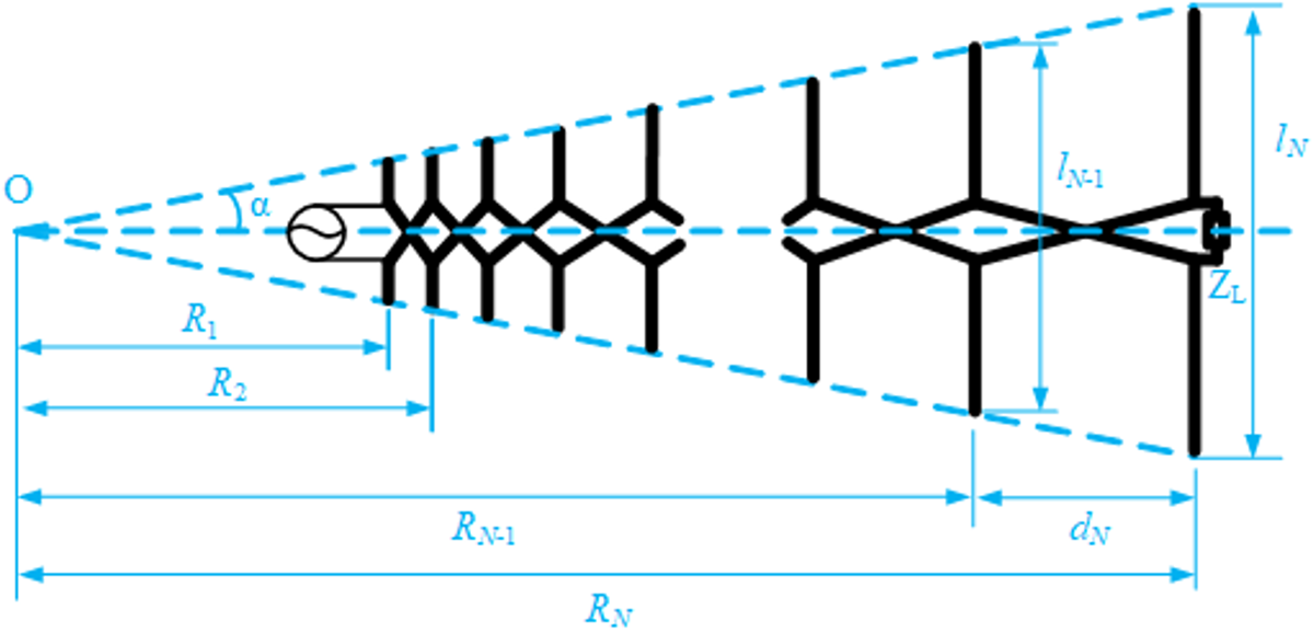
LPDA is composed of several parallel symmetric oscillators arranged in a certain proportion [Reference De Vito and Stracca22]. Each oscillator is connected to a pair of dual line transmission lines, called a collection line, and fed through the collection line. The feed source is connected to one end of the shortest oscillator, and adjacent oscillators are cross fed. Short circuiting or adding matching loads at the end of the collection line can reduce terminal reflection and improve the VSWR characteristics at the low-frequency end. Its structure [Reference Wang, Wu, Li and Qin7] is shown in Fig. 1.
The structure diagram of the LPDA.

LPDA consists of N parallel symmetric oscillators, the i-th oscillator have a length of  ${l_i}{\kern 1pt} {\kern 1pt} \left( {i = 1,\ldots,N} \right)$, a radius of
 ${a_i}\left( {i = 1,\ldots,N} \right)$, a distance of
 ${R_i}$ from the geometric vertex O, and a distance of
 ${d_i}$ from the i-th oscillator, so
 \begin{equation}\frac{{{l_i}}}{{{l_{i + 1}}}} = \frac{{{a_i}}}{{{a_{i + 1}}}} = \frac{{{R_i}}}{{{R_{i + 1}}}} = \frac{{{d_i}}}{{{d_{i + 1}}}} = \tau \lt 1,{\kern 1pt} {\kern 1pt} {\kern 1pt} {\kern 1pt} {\kern 1pt} \left( {i = 1,\ldots,N - 1} \right)\end{equation}
 \begin{equation}\sigma {\text{ = }}\frac{{{d_i}}}{{2{l_i}}} \lt 1,{\kern 1pt} {\kern 1pt} {\kern 1pt} {\kern 1pt} {\kern 1pt} \left( {i = 1,\ldots,N - 1} \right)\end{equation}
 \begin{equation}\alpha {\text{ = arctan}}\frac{{{l_i}}}{{2{R_i}}},{\kern 1pt} {\kern 1pt} {\kern 1pt} {\kern 1pt} {\kern 1pt} \left( {i = 1,\ldots,N - 1} \right)\end{equation}
where  $\tau $,
 $\sigma $ or
 $\alpha $ have the following relationship:
 \begin{equation}\sigma {\text{ = }}\frac{{1 - \tau }}{{4\tan \alpha }}\end{equation}
The overall structure of LPDA is mainly determined by the scaling factor  $\tau $, interval factor
 $\sigma $, and structural angle
 $\alpha $, usually taking
 $\tau {\text{ = 0}}{\text{.8}} \sim 0.95{\kern 1pt} $,
 $\sigma {\text{ = }}0.08 \sim 0.51$. Once the two of
 $\tau $,
 $\sigma $ or
 $\alpha $ are determined, the geometric structure of LPDA is also determined. If the bandwidth
 $B = {{{f_{\max }}} \mathord{\left/
{\vphantom {{{f_{\max }}} {{f_{\min }}}}} \right.
} {{f_{\min }}}}$ is given, the number of oscillators can be determined by
 \begin{equation}N = 1 + \frac{{\ln B}}{{\ln (1/\tau )}}\end{equation}
The “radiation zone” usually refers to the area between several oscillators where the excitation current value is equal to one-third of the maximum excitation current. The number  ${N_a}$ of oscillators in this area is generally determined by geometric parameters
 $\tau $ and
 $\sigma $, which can be approximated as
 \begin{equation}{N_a} = 1 + \frac{{\lg \left( {{{{K_2}} \mathord{\left/
{\vphantom {{{K_2}} {{K_1}}}} \right.
} {{K_1}}}} \right)}}{{\lg \tau }}\end{equation}
 \begin{equation}{K_1} = 1.01 - 0.519\tau \end{equation}
 \begin{equation}\begin{aligned}
{K_2} & = 7.10{\tau ^3} - 21.3{\tau ^2} + 21.98\tau - 7.30 \\
& \quad + \sigma \left( {21.82 - 66\tau + 62.12{\tau ^2} - 18.29{\tau ^3}} \right) \\
\end{aligned} \end{equation}
where  ${K_1}$ and
 ${K_2}$ are the cutoff constants for the low and high ends of the operating frequency band, respectively.
 ${N_a}$ is generally not less than 3, and the larger its value, the stronger the directionality and the higher the gain.
To meet the operating frequency  $f \in \left[ {{f_{\min }},{f_{\max }}} \right]$ of the antenna, corresponding to the maximum and minimum operating wavelengths
 ${\lambda _{\max }}$,
 ${\lambda _{\min }}$, the general requirements are
 \begin{equation}\left\{ {\begin{array}{*{20}{c}}
{{l_1} = {K_1}{\lambda _{\min }}} \\
{{l_N} = {K_2}{\lambda _{\max }}}
\end{array}} \right.\end{equation}
The designed LPDA operates at a frequency of 13 to 28 MHz, corresponding to a wavelength range of 23.08 to 10.71 meters. Referring to curves of the directivity coefficient versus  $\tau $ and
 $\sigma $ provided by R. L. Carrel [Reference Carrel23],
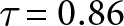 $\tau {\text{ = }}0.86$ and
 $\sigma = 0.16$ are selected here. If the length of the longest/shortest element is taken as half of the longest/shortest operating wavelength, then
 ${l_N} = {{{\lambda _N}} \mathord{\left/
{\vphantom {{{\lambda _N}} 2}} \right.
} 2}{\text{ = }}11.5{\text{m}}$,
 ${l_1} = {{{\lambda _1}} \mathord{\left/
{\vphantom {{{\lambda _1}} 2}} \right.
} 2} = 5.4{\text{m}}$, and from
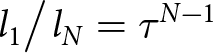 ${{{l_1}} \mathord{\left/
{\vphantom {{{l_1}} {{l_N} = {\tau ^{N - 1}}}}} \right.
} {{l_N} = {\tau ^{N - 1}}}}$, the number of elements
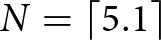 $N = \left\lceil {5.1} \right\rceil $ can be obtained. Since the “radiation zone” of LPDA is not accomplished by a single element but by several elements working together, it is often necessary to add elements at both ends of the antenna to improve the performance at the high and low ends of the operating frequency band. From equations (7) to (8), K 1 and K 2 can be obtained, and then
 ${l_N} = 13.02 {\text{m}}$,
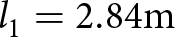 ${l_1} = 2.84 {\text{m}}$, at this time, the number of elements
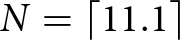 $N = \left\lceil {11.1} \right\rceil $. Considering all the above, the number of elements of the designed antenna in this paper is taken as a compromise,
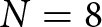 $N = 8$. The lengths and spacings of each element are shown in Table 1. At this time, the length of the collinear line is
 ${\text{D = }}\sum\limits_{i = 1}^N {{d_i}} = 19.09 {\text{m}}$, the structural angle of the antenna is
 $2\alpha = {24.68^ \circ }$, and the distance from the shortest element to the vertex O is
 ${R_1}{\text{ = }}\frac{{{l_1}}}{{2\tan \alpha }} = 10.17 {\text{m}}$, so the size of the LPDA unit antenna is 12.8 × 19.1 m2.
Length and spacing of LPDA oscillators

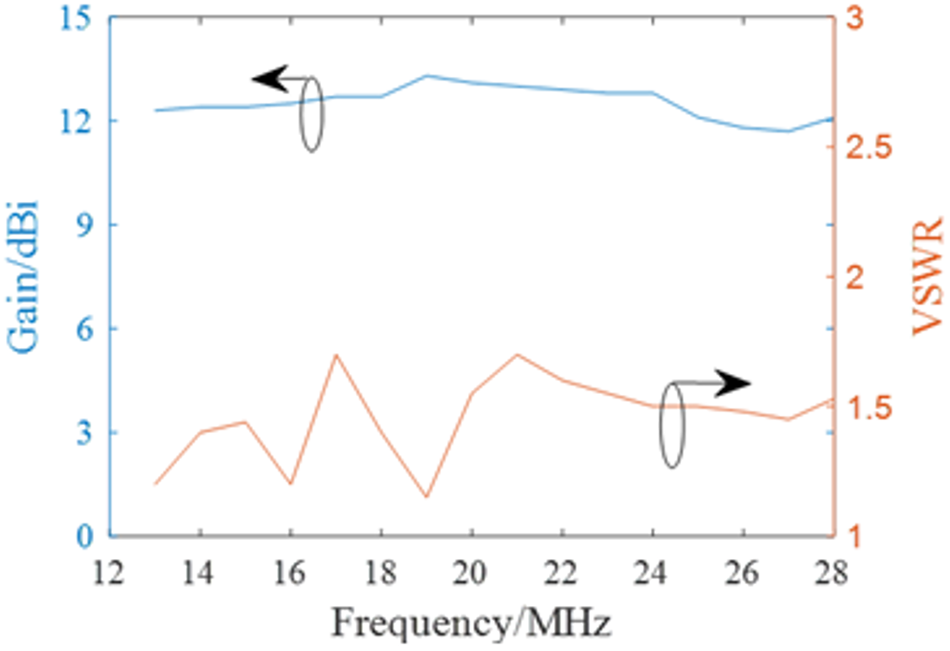
The simulation performance of the LPDA unit radiator antenna is presented in Fig. 2. Within the operating frequency band, its VSWR is all ≤1.7, and the average value is 1.4. The maximum gains are all ≥11.8 dBi, and the average value is 12.5 dBi.
The performance of the LPDA unit radiator antenna.

Fan-shaped array model
In order to further improve the gain, a single LPDA can be arranged in a certain way to form a multi-elements LPDA array. By using two layers of horizontally polarized LPDA for array formation, the vertical plane (H-plane) beam width can be compressed, and the horizontally polarized LPDA can be horizontally arranged to compress the horizontal plane (E-plane) beam width and improve the directional gain of the array.
LPDA is generally formed in the form of a linear or fan-shaped array [Reference Zhenghui, Weiming and Ren24]. Due to the wide operating frequency band, the difference between the shortest and longest oscillators is significant. If a linear array is used, while avoiding the overlap of the longest oscillators at the rear end of adjacent unit antennas, the spacing between the shortest oscillators at the front end will be too large, which will cause serious grating lobe effect and even beam deflection in the high-frequency range of the linear array. Moreover, the linear array greatly increases the size of the array and increases the footprint of the array. Therefore, this paper will adopt a fan-shaped array, which can not only shorten the spacing between the antenna front ends, effectively avoid the appearance of grating lobes, but also reduce the array size at the front end.
For the LPDA fan-shaped array with horizontal polarization near the ground, the current distribution of each oscillator in the array is related to the height of each oscillator, the angle between antenna elements, etc. [Reference Xiaolei25], which directly affects its input impedance, pattern, and gain characteristics. The LPDA fan-shaped array consists of 2 × 3 elements, as shown in Fig.3. The array consists of 6 units, divided into upper and lower layers, each layer containing 3 units, which symmetric about the xoy plane, the horizontal fan-shaped angle between the two layers is  $\delta $, and the vertices intersect at point O’ or O’’. The two layers of antennas are horizontally distributed, with the first and second layer being H 1 and H 2 away from the ground, and the vertical spacing between the upper and lower layers of antennas is
 $\Delta H = {H_2} - {H_1}$. The feeding of each unit is set at the shorter oscillator end of the antenna. V1, V2, V3, V4, V5, and V6 are the feeding sources for the upper or lower units, respectively.
3D diagram of 2 × 3-element LPDA array.

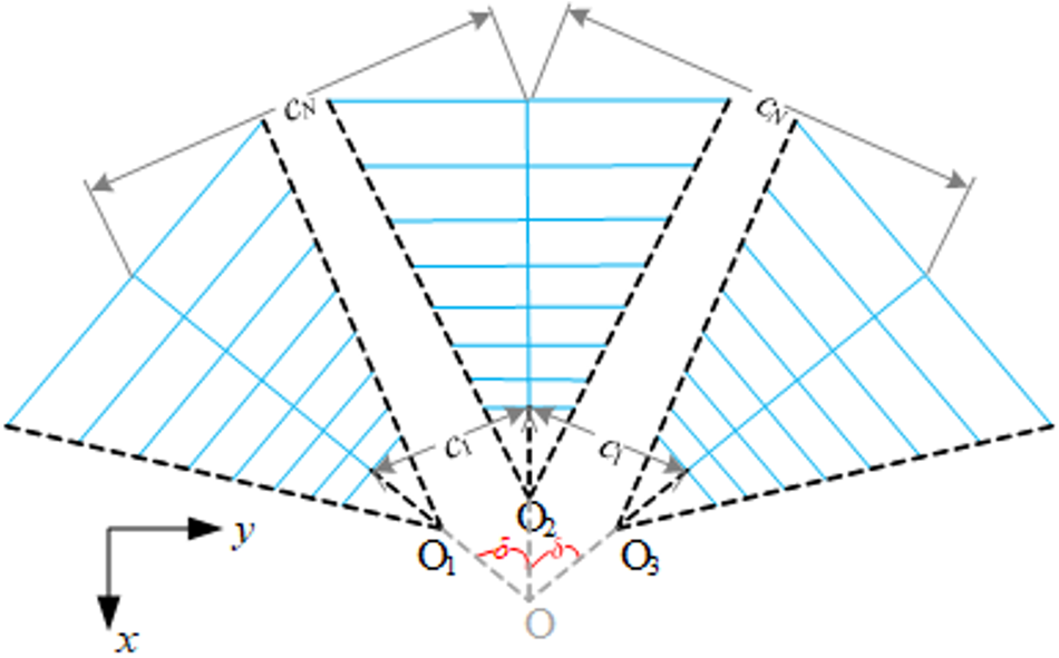
Three antennas on each layer in details, as shown in Fig. 4, are distributed in a fan-shaped pattern with equal angle of δ around point O, and symmetrically distributed on both sides of the axis, and their collection lines intersect at point O along the extension line of the structural vertex (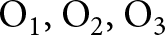 ${{\text{O}}_{\text{1}}}{\text{, }}{{\text{O}}_2}{\text{, }}{{\text{O}}_3}$) direction, so the distance between the intersection point O and the vertices of each structure is equal. The centers distance between the shortest oscillator of adjacent units is
 ${c_1}$, and that between the longest oscillator is
 ${c_N}$.
For an M-element near ground horizontally polarized LPDA fan-shaped array, each LPDA is composed of N dipole oscillators. The imaginary vertices of each element in the fan-shaped array are located on a circle with a radius of 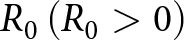 ${R_0}\left( {{R_0} \gt 0} \right)$, and the center of the circle coincides with the coordinate origin O, that is
 $\overline {{O_1}O} = \overline {{O_2}O} = \overline {{O_3}O} = {R_0}$, the entire fan-shaped array is symmetric about the x-axis. The angle between the m-th (m = 1, 2, .., M) element and the x-axis is represented by
 ${\delta _m}$. For the n-th (n = 1, 2, .., N) oscillator surface, the Galerkin method [Reference Brousseau, Airiau, Boury and Bourdillon26, Reference Parreira, Silva, Fonseca and Mesquita27] can be used to
 \begin{equation}\sum\limits_{m = 1}^M {\sum\limits_{n = 1}^N {\sum\limits_{k = 1}^K {{I_{mn,k}}Z_k^{mn}} } } = {V_{mn,k}}\end{equation}
 \begin{align}
Z_k^{mn} &= - \frac{1}{j\omega \varepsilon_0} \int_{y_{mn,k - 1}}^{y_{mn,k + 1}}
\frac{\sin\left(k_0\left(h_n - \left| y_{mn} - y_{mn,k} \right|\right)\right)}{\sin(k_0 h_n)} \nonumber\\
&\quad \times \left[ E_{mn,mxk}(x_{mn}, y_{mn}, z_n) \sin(\delta_m - \delta_n)\right.\nonumber\\
&\quad \left.+\,E_{mn,myk}(x_{mn}, y_{mn}, z_n) \cos(\delta_m - \delta_n) \right] \, \mathrm{d}y_{mn}
\end{align}
 \begin{equation}{V_{mn,k}} = \left\{ {\begin{array}{*{20}{c}}
{{U_{A,mn}}, at \left( {{x_{mn}},0,{z_{mn}}} \right)} \\
{0, others}
\end{array}} \right.\end{equation}
Top view of 1 × 3 element LPDA array.

where  ${U_{A,mn}}$ is the excitation voltage of the mn-th oscillator,
 ${I_{mn,k}}$ is the current distribution on the k-th (k = 1, 2, .., K) segment of the n-th oscillator in the m-th array element, and
 ${h_n}$ is the segment length of the n-th oscillator. The corresponding scattered field components generated by the segmented surface of the oscillator are
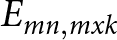 ${E_{mn,mxk}}$,
 ${E_{mn,myk}}$.
By combining the iterative method [Reference Weiliang, Changhong and Xiaowei28] or the equivalent circuit method [Reference Butson and Thompson29], the current distribution on each element of the array can be solved, thereby obtaining the input impedance of each LPDA unit in the array as well as the array’s radiation pattern, gain, etc. When analyzing LPDA and the uniformly excited fan-shaped array composed of it, to reduce the computational load, the equivalent circuit method can be adopted here. The VSWR of each unit can be expressed as
 \begin{equation}\left\{ {\begin{array}{*{20}{c}}
{VSWR = \frac{{1 + \left| {{\Gamma _1}} \right|}}{{1 + \left| {{\Gamma _1}} \right|}}} \\[6pt]
{{\Gamma _1} = \frac{{{Z_{in}} - {Z_c}}}{{{Z_{in}} + {Z_c}}} = \frac{{{U_{A1}} - {I_{in}}{Z_c}}}{{{U_{A1}} + {I_{in}}{Z_c}}}}
\end{array}} \right.\end{equation}
where 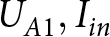 ${U_{A1}}, {I_{in}}$ respectively represent the excitation voltage and current at the first oscillator location (the feeding point).
The directional pattern function of the LPDA fan-shaped array with horizontal polarization near the ground is represented as
 \begin{align}
{f_h}\left( {\theta ,\varphi } \right) & = \mathop \sum \limits_{m = 1}^M \mathop \sum \limits_{p = 1}^N \frac{{\exp \left[ {j{k_0}{x_{mn}}\sin \theta \cos \left( {\varphi - {\delta _m}} \right)} \right]}}{{\left[ {1 - {{\sin }^2}\theta {{\sin }^2}\left( {\varphi - {\delta _m}} \right)} \right]\sin {k_0}{h_n}}}\nonumber\\
& \quad\left\{ {\cos \left[ {{k_0}{h_n}\sin \theta \sin \left( {\varphi - {\delta _m}} \right) - \cos {k_0}{h_n}} \right]} \right\} \nonumber\\
& \quad\cdot\left[ {\exp \left( {j{k_0}{z_n}\cos \theta } \right) + {R_h}\exp \left( { - j{k_0}{z_n}\cos \theta } \right)} \right]\nonumber\\
&\quad \mathop \sum \limits_{k = 1}^K {I_{mn,k}}\exp \left[ {j{k_0}{y_{mn,k}}\sin \theta \sin \left( {\varphi - {\delta _m}} \right)} \right]
\end{align}
The E-plane 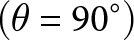 $\left( {\theta {\text{ = }}{{90}^ \circ }} \right)$ directional pattern function is
 \begin{align}
{f_{h{\text{E}}}}\left( \varphi \right) & = \mathop \sum \limits_{m = 1}^M \mathop \sum \limits_{n = 1}^N \frac{{\exp \left[ {j{k_0}{x_{mn}}\cos \left( {\varphi - {\delta _m}} \right)} \right]}}{{\left[ {1 - {{\sin }^2}\left( {\varphi - {\delta _m}} \right)} \right]\sin {k_0}{h_n}}}\nonumber\\
&\quad \cos \left[ {{k_0}{h_n}\sin \left( {\varphi - {\delta _m}} \right) - \cos {k_0}{h_n}} \right] \nonumber\\
& \quad{\cdot\left( {1 + {R_h}} \right)\mathop \sum \limits_{k = 1}^K {I_{mn,k}}\exp \left[ {j{k_0}{y_{mn,k}}\sin \left( {\varphi - {\delta _m}} \right)} \right]}
\end{align}
The H-plane  $\left( {\varphi {\text{ = }}{0^ \circ }} \right)$ directional pattern function is
 \begin{align}
{f_{hH}}\left( \theta \right) & = \mathop \sum \limits_{m = 1}^M \mathop \sum \limits_{n = 1}^N \frac{{\exp \left[ {j{k_0}{x_{mn}}\sin \theta \cos {\delta _m}} \right]}}{{\left[ {1 - {{\sin }^2}\theta {{\sin }^2}{\delta _m}} \right]\sin {k_0}{h_n}}}\nonumber\\
& \quad\cos \left( { - {k_0}{h_n}\sin \theta \sin {\delta _m} - \cos {k_0}{h_n}} \right) \nonumber\\
&\quad\cdot\left[ {\exp \left( {j{k_0}{z_n}\cos \theta } \right) + {R_h}\exp \left( { - j{k_0}{z_n}\cos \theta } \right)} \right]\nonumber\\
&\quad \mathop \sum \limits_{k = 1}^K {I_{mn,k}}\exp \left( { - j{k_0}{y_{mn,k}}\sin \theta \sin {\delta _m}} \right)
\end{align}
Array optimization model
In order to improve the overall gain of the array, solve the array effect of grating lobe and coupling in band, a 2 × 3 element double-layer fan-shaped LPDA array structure is further analyzed and optimized here.
Broadband decoupling
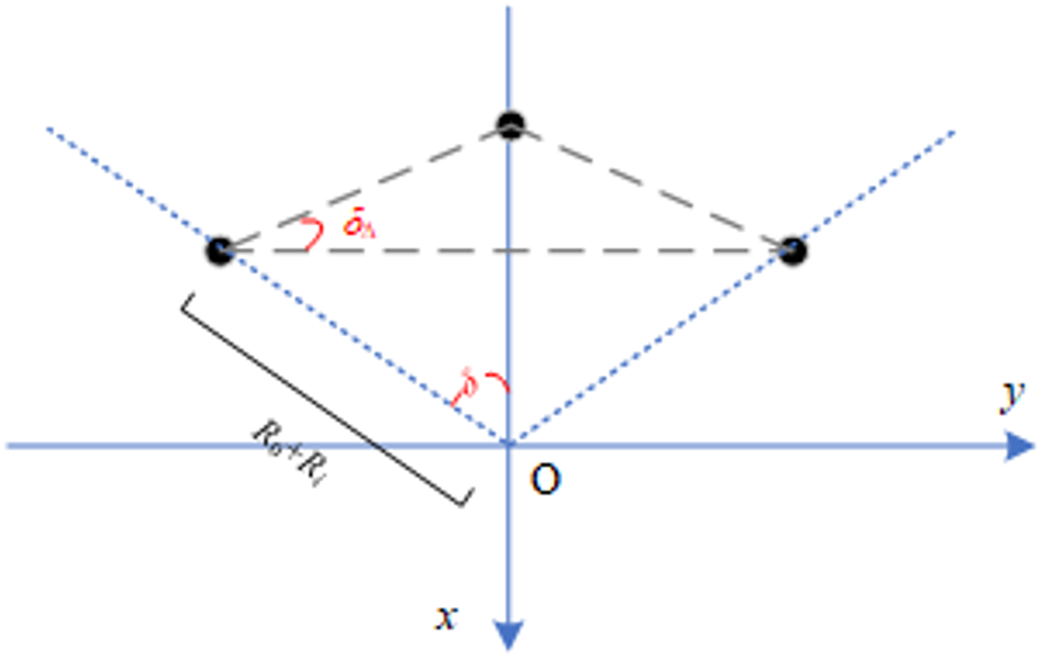
For the 2 × 3 element phased array studied in this paper, which is fan-shaped distributed on the horizontal plane, the centers of each layer of array elements are distributed in an isosceles triangular grid, as shown in Fig. 5. Let the isosceles triangle grid have an isosceles angle of  ${\delta _\Delta }$. Since the distance between the element center and the origin O is equal, there is a relationship between the isosceles angle
 ${\delta _\Delta }$ and the fan-shaped angle
 $\delta $ as follows:
 \begin{equation}{\delta _\Delta } = \frac{\delta }{2}\end{equation}
Distribution of triangular grid in fan-shaped array.

Due to the fact that each element is exactly the same and the spatial distribution is symmetric about the y-axis, a fan-shaped phased array not only has an isosceles triangle at the element center, but also its structural vertices or the collection points of each oscillator form an isosceles triangle, so
 \begin{equation}{c_i} = \left( {{R_0} + {R_i}} \right)\cdot2\sin \frac{\delta }{2},{\text{ }}i = 1,2,\ldots,N\end{equation}
where  ${R_0} = \overline {{O_1}O} = \overline {{O_2}O} = \overline {{O_3}O} $ refers to Fig. 3 or Fig. 4,
 ${R_i}{\kern 1pt} \left( {i = 1,\ldots,N} \right)$ refers to Fig. 1.
To avoid affecting the normal operation of the antenna array, adjacent antennas on the left and right should not overlap with each other, so
 \begin{equation}{c_i} \gt {l_i}\cos \frac{\delta }{2}\end{equation}
From equations (15) and (16), it can be concluded that:
 \begin{equation}\delta \gt 2\arctan \frac{{{l_i}}}{{2\left( {{R_i} + {R_0}} \right)}} = 2\arctan \frac{1}{{{1 \mathord{\left/
{\vphantom {1 {\tan \alpha }}} \right.
} {\tan \alpha }} + {{2{R_0}} \mathord{\left/
{\vphantom {{2{R_0}} {{l_i}}}} \right.
} {{l_i}}}}}\end{equation}
Combining equation (9), there are
 \begin{equation}\left\{ {\begin{array}{*{20}{c}}
{\delta \gt 2\arctan \frac{1}{{{{\tan }^{ - 1}}\alpha + {{2{R_0}} \mathord{\left/
{\vphantom {{2{R_0}} {\left( {{K_1}{\lambda _{\min }}} \right)}}} \right.
} {\left( {{K_1}{\lambda _{\min }}} \right)}}}}} \\[8pt]
{\delta \gt 2\arctan \frac{1}{{{{\tan }^{ - 1}}\alpha + {{2{R_0}} \mathord{\left/
{\vphantom {{2{R_0}} {\left( {{K_2}{\lambda _{\max }}} \right)}}} \right.
} {\left( {{K_2}{\lambda _{\max }}} \right)}}}}}
\end{array}} \right.\end{equation}
When  ${R_0}{\text{ = }}0$, the three structural vertices (
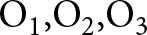 ${{\text{O}}_{\text{1}}}{\text{,}}{{\text{O}}_2}{\text{,}}{{\text{O}}_3}$) coincide at O, and equation (18) is simplified as
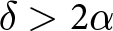 $\delta \gt 2\alpha $.
Broadband grating lobe suppression
To ensure that the LPDA array does not generate grating lobes in the high frequency direction pattern, the spacing c between the array elements should meet [Reference Manohar and Samii30]
 \begin{equation}{c_1} \lt {\lambda _{\min }}\end{equation}
where  ${\lambda _{\min }}$ is the minimum operating wavelength.
Combining equations (3), (9), and (15), then
 \begin{equation}\delta \lt 2{\sin ^{ - 1}}\left[ {\frac{{{\lambda _{\min }}}}{{2\left( {{R_0} + {R_1}} \right)}}} \right] = 2{\sin ^{ - 1}}\left[ {\frac{1}{{\left( {{{2{R_0}} \mathord{\left/
{\vphantom {{2{R_0}} {{\lambda _{\min }}}}} \right.
} {{\lambda _{\min }}}} + {K_1}\tan \alpha } \right)}}} \right]\end{equation}
Array optimization problem
To meet the performance requirements of low coupling and non-grating lobes, the array design problem needs to be transformed into an optimization problem for array electrical parameters, such as standing wave ratio bandwidth, maximum gain, and sidelobes or grating lobes. This optimization problem has three clear optimization objectives, regarding standing wave ratio, maximum gain, and grating lobe or sidelobe.
1) As for broadband decoupling problem, the design expectation is to have a smaller VSWR within the operating frequency band, generally  $VSW{R_{{\omega _i}}}\left( {{R_0},\delta } \right) \leqslant 2$, so the first target
 ${f_1}$ about VSWR can be expressed as
 \begin{equation}{f_1} = \min \sum\limits_{i = 1}^I {VSWR\left( {{\omega _i}} \right)} \end{equation}
2) As for broadband high gain problem, it is necessary to meet the requirement of maximizing the main beam gain (maximum gain) within the operating frequency band. The maximum gain for the second target  ${f_2}$is expressed as
 \begin{equation}{f_2} = \mathop {\max }\limits_{\varphi = {\phi _0}} \sum\limits_{i = 1}^I {{f_h}\left( {\theta ,\varphi ,{\omega _i}} \right)} \end{equation}
3) As for broadband grating lobe suppression problem, to avoid the generation of grating lobes or suppression of sidelobe levels, it is necessary to minimize the sidelobe level. The third target  ${f_3}$ about sidelobe can be expressed as
 \begin{equation}{f_3} = \min \sum\limits_{i = 1}^I {\mathop {\max }\limits_{_{\varphi = \overline {{\phi _0}} }} {f_h}\left( {\theta ,\varphi ,{\omega _i}} \right)} \end{equation}
For the optimization problem of the fan-shaped phased array to be optimized here, once the element antenna is determined, the scaling factor  $\tau $, spacing factor
 $\sigma $, and structural angle
 $\alpha $ are determined values, and then the truncation constant
 ${K_1}$,
 ${K_2}$ are also determined. The operating frequency
 ${\omega _i}$ and the maximum beam scanning angle
 ${\phi _m}$ are determined demand indicators, therefore, only the vertex spacing
 ${R_0}$ and fan-shaped angle
 $\delta $ are unknown variables. And
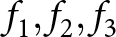 ${f_1},{f_2},{f_3}$ are not independent objective functions, and there is coupling or even constraint between them.
 ${R_0}$ and
 $\delta $ also have mutual relationships. In addition, under ideal ground conditions, it is also related to the erection height
 ${H_1}$ and the spacing
 $\Delta H$ between the upper and lower layer of the array, which should satisfy
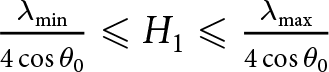 $\frac{{{\lambda _{\min }}}}{{4\cos {\theta _0}}} \leqslant {H_1} \leqslant \frac{{{\lambda _{\max }}}}{{4\cos {\theta _0}}}$ and
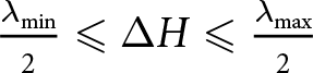 $\frac{{{\lambda _{\min }}}}{2} \leqslant \Delta H \leqslant \frac{{{\lambda _{\max }}}}{2}$, where
 ${\theta _0}$ is the angle between the beam and the Z-axis. Comprehensively considering the intrinsic relationships of each other among the above-mentioned variables, the comprehensive optimization problem of the fan-shaped phased array is thus a multi-objective optimization problem, which can be further transformed into
 \begin{align}
F(R_0, \delta, H_1, \Delta H) &= \min_{R_0, \delta, H_1, \Delta H} \Bigg\{
\sum_{i = 1}^I A_i \, VSWR(\omega_i) \nonumber\\
&\quad + \sum_{i = 1}^I B_i \left[ G_0 - \mathop {{f_h}}\limits_{\varphi = \phi_0}(\omega_i) \right] \nonumber\\
&\quad + \sum_{i = 1}^I C_i \left[ \max \mathop {{f_h}}\limits_{\varphi \in \overline{\phi_0}}(\omega_i) \right]
\Bigg\}
\end{align}
where  $VSWR\left( {{\omega _i}} \right) = VSWR\left( {{\omega _i},{R_0},\delta ,{H_1},\Delta H} \right)$,
 $i = 1,2,\ldots,I$,
 $\mathop {{f_h}}\limits_{\varphi = {\phi _0}} \left( {{\omega _i}} \right) = \mathop {{f_h}}\limits_{\varphi = {\phi _0}} \left( {{\omega _i},{R_0},\delta ,{H_1},\Delta H} \right)$,
 $\mathop {{f_h}}\limits_{\varphi \in \overline {{\phi _0}} } \left( {{\omega _i}} \right) = \mathop {{f_h}}\limits_{\varphi \in \overline {{\phi _0}} } \left( {{\omega _i},{R_0},\delta ,{H_1},\Delta H} \right)$ are the VSWR, main beam gain (maximum gain), and sidelobe gain of the antenna at the i-th frequency point
 $\left( {{\omega _i}} \right)$ in the operating frequency band, respectively.
 ${G_0}$ is the maximum gain demand index,
 $\varphi $ is the azimuth angle,
 ${\phi _0} \in \left[ { - {\phi _m}, + {\phi _m}} \right]$ is the horizontal scanning beam direction,
 ${\phi _m}$ is the maximum deviation angle of the azimuth beam,
 $S$ is the angle range where the sidelobe is located, and
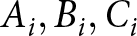 ${A_i}, {B_i}, {C_i}$ are the weight coefficients, which can be adjusted according to specific design index requirements.
Combining the above constraints, the comprehensive optimization problem of fan-shaped phased array can be described as
 \begin{equation}
\begin{cases}
F(R_0, \delta, H_1, \Delta H) = \displaystyle \min\limits_{R_0, \delta}\\
\Bigg\{ \sum\limits_{i = 1}^I A_i \, VSWR(\omega_i)
+ \sum\limits_{i = 1}^I B_i \left[ G_0 - \mathop {{{f}_h}}\limits_{\varphi = \phi_0}(\omega_i) \right] \\
\quad + \sum\limits_{i = 1}^I C_i \left[ \displaystyle \max_{\varphi \in \overline{\phi_0}} f_h(\omega_i) \right]
\Bigg\} \\[12pt]
\delta \le 2 \arctan \left( \frac{1}{\tan^{-1} \alpha + \dfrac{2 R_0}{K_1 \lambda_{\min}}} \right) \\[15pt]
\delta \le 2 \arctan \left( \frac{1}{\tan^{-1} \alpha + \dfrac{2 R_0}{K_2 \lambda_{\max}}} \right) \\[15pt]
\delta \ge 2 \sin^{-1} \left(\frac{1}{\dfrac{2 R_0}{\lambda_{\min}} + K_1 \tan \alpha} \right) \\[15pt]
\dfrac{\lambda_{\min}}{4 \cos \theta_0} \leq H_1 \leq \dfrac{\lambda_{\max}}{4 \cos \theta_0} \\[10pt]
\dfrac{\lambda_{\min}}{2} \leq \Delta H \leq \dfrac{\lambda_{\max}}{2}
\end{cases}
\end{equation}
Optimization method
The proposal of the grasshopper optimization algorithm (GOA) [Reference Saremi, Mirjalili and Lewis31] is inspired by the social behavior of natural grasshopper populations. It is a new type of natural inspired algorithm to find food sources for achieving search objectives by a search method of explores and develops. The mathematical model that modifies and simulates the behavior of grasshopper populations can be expressed as
 \begin{equation}
\left\{
\begin{array}{c}
X_i^d = c \left( \displaystyle \sum\limits_{\substack{j = 1 \\ j \ne i}}^N c \cdot \frac{ub_d - lb_d}{2} \cdot s\left( \left| x_j^d - x_i^d \right| \right) \cdot \frac{x_j - x_i}{d_{ij}} \right) + \widehat{T_d} \\
c = c_{\text{max}} - \frac{l \left( c_{\text{max}} - c_{\text{min}} \right)}{L}
\end{array}
\right.
\end{equation}
where  $X_i^d$ represents the position of the
 $i$-th grasshopper in d-dimensional solution space,
 $\left| {x_j^d - x_i^d} \right|$ means the distance between the
 $i{\text{ - th}}$ and the
 $j{\text{ - th}}$ grasshopper,
 $u{b_d}$,
 $l{b_d}$are the upper or lower bound of the d-th dimensional solution space, respectively.
 $\widehat {{T_d}}$ is the d-dimensional target value.
 $c$ is a reduction coefficient to control comfort area, exclusion area and attraction area, whose maximum and minimum values are
 ${c_{{\text{max}}}},{\kern 1pt} {\kern 1pt} {\kern 1pt} {\kern 1pt} {\kern 1pt} {c_{{\text{min}}}}$ respectively.
 $l$,
 $L$are the current or maximum number of iterations, respectively.
In response to the defect that the GOA parameter c decreases too slowly in the early stage and too quickly in the later stage, an arc adaptive adjustment strategy is adopted to update the parameter c.
 \begin{equation}c = {\left( {{c_{{\text{max}}}}--\frac{{l\left( {{c_{{\text{max}}}}--{c_{{\text{min}}}}} \right)}}{L}} \right)^2}\end{equation}
In order to make the global search range more uniform and improve the efficiency of population position reconfiguration, a uniform model of logistic chaos equation [32] is used to update the population position.
 \begin{equation}\left. \begin{gathered}
{X_{n + 1}} = - 4X_n^2 + 4{X_n} \hfill \\
{Z_n} = \frac{1}{{{\pi }}}\arcsin \left( {2{X_n} - 1} \right) \hfill \\
\end{gathered} \right\}\end{equation}
where  ${X_0} \in [0,{\kern 1pt} {\kern 1pt} {\kern 1pt} {\kern 1pt} 1]$ represents the initialization sequence, and
 ${Z_n}$ follows a uniform chaotic distribution within
 $\left[ { - \frac{1}{2},{\kern 1pt} {\kern 1pt} {\kern 1pt} {\kern 1pt} \frac{1}{2}} \right]$.
The multi LPDA fan-shaped array structure is quite complex, making it difficult to derive analytical methods for expression. Here, based on the mathematical model of LPDA unit antenna, a phased array optimization model is established with vertex spacing  ${R_0}$ and fan-shaped angle
 $\delta $ as the variables to be optimized under the required operating frequency
 ${\omega _i}\left( {i = 1,2,\ldots,I} \right)$ and beam scanning direction
 ${\phi _0} \in \left[ { - {\phi _m}, + {\phi _m}} \right]$. The specific description of the optimization method for multivariate fan-shaped arrays based on the improved GOA algorithm is as follows:
Step 1: Set parameters: operating frequency  ${\omega _i}\left( {i = 1,2,\ldots,I} \right)$, beam scanning direction
 ${\phi _0} \in \left[ { - {\phi _m}, + {\phi _m}} \right]$.
Step 2: Establish the mathematical model of LPDA and use it as a unit antenna to form a 2 × 3 element fan-shaped array on an infinite PEC ground, as shown in Fig. 6.
Cadfeko model of 2 × 3-element LPDA array.

Step 3: Set the variables  $\left( {{R_0},\delta ,{H_1},\Delta H} \right)$ to be optimized in the editable file of the fan-shaped array model as the variable parameters to be optimized, and establish the array optimization problem
 $F\left( {{X^4}} \right)$ for the 4D optimization variable
 ${X^4} = \left\{ {{R_0},\delta ,{H_1},\Delta H} \right\}$, so that it obtains the minimum value within the defined domain
 $\left[ {X_{\min }^4,{\kern 1pt} {\kern 1pt} {\kern 1pt} {\kern 1pt} X_{\max }^4} \right]$.
Step 4: Based on heuristic intelligent optimization algorithms [Reference Wang, Kang and Li32, Reference Hongyan, Huifang and Hongyu33], initialize each parameter to be optimized in the solution space, calculate the initial fitness value of the objective function, and find the optimal target position of the initial objective.
Step 5: Adopt an adaptive adjustment strategy to update the optimization solution parameters, and calculate the fitness value of the next generation objective function to obtain the optimal solution space for this generation of objectives.
Step 6: Reconfigure the solutions that exceed the search space according to the constraints of equation (25), calculate their fitness values, and update their target values.
Step 7: Check if the current iteration count exceeds the maximum iteration count. If not, repeat steps 5–6 until it is determined as yes.
Phased array optimization design
Array distribution optimization
For the comprehensive optimization problems of the 2 × 3-element LPDA fan-shaped array shown in (28) regarding broadband high gain, decoupling, and grating lobe suppression, etc. Here, based on the array mathematical model shown in (13) to (14), the improved GOA algorithm is adopted to optimize the variables  $\left( {{R_0},\delta ,{H_1},\Delta H} \right)$ to be optimized of the fan-shaped array. After multiple optimizations, the best optimization result of the fan-shaped array distribution was obtained, as shown in Table 2.
Optimized parameter results of the fan-shaped array

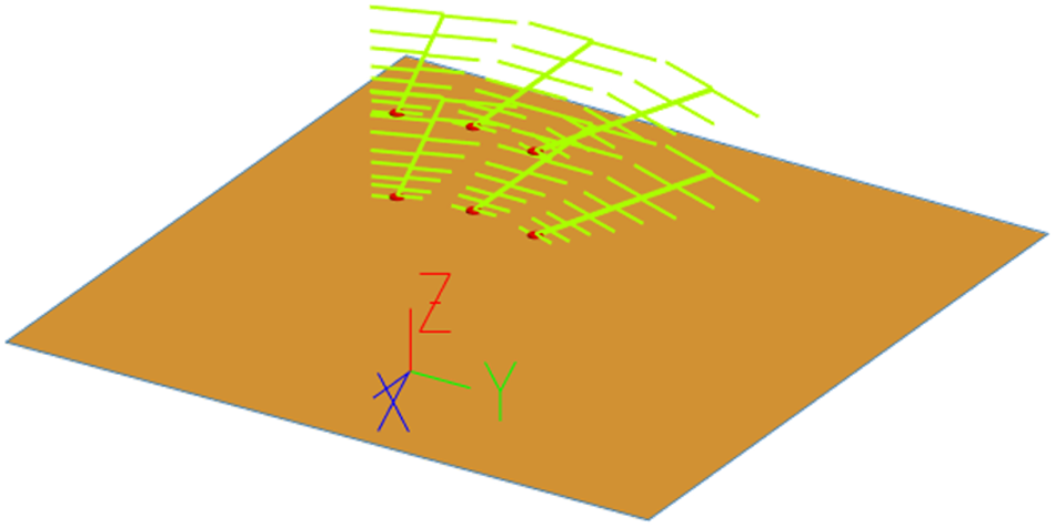
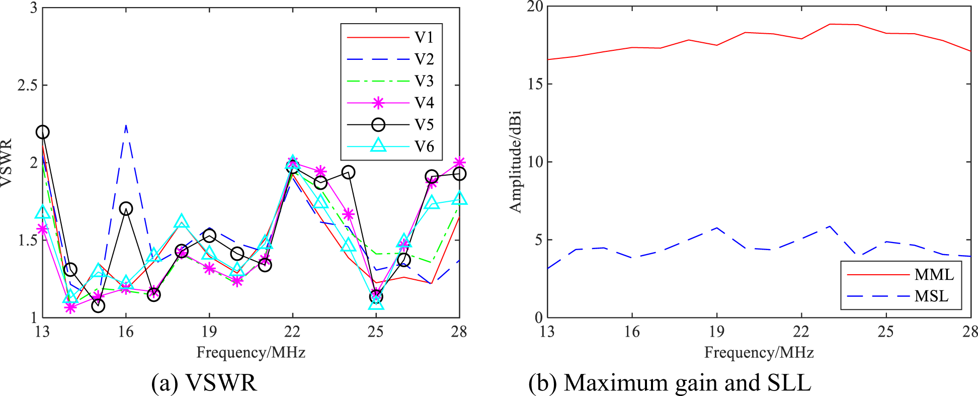
The Cadfeko model of the fan-shaped array is established. The ground medium was set as an ideal infinite conductive plane, and a balanced-unbalanced converter is used for power feeding. The material of the antenna element is copper, as shown in Fig. 6. The optimization results of Table 2 were brought into the Cadfeko model of the fan-shaped array for simulation. The parameters such as the VSWR, the maximum main-lobe (MML) gain and maximum sidelobe (MSL) gain of each port of the fan-shaped array can be obtained as shown in Fig. 7.
Optimization results of 2 × 3-element LPDA array.

It can be seen from the simulation results in Fig. 7 that within the working frequency band, the maximum VSWR of each antenna unit port all satisfy ≤2.2, with the average values are 1.45, 1.51, 1.45, 1.48, 1.58, and 1.49 respectively. The MML gain of the fan-shaped array are all ≥16.6 dBi, with an average value of 17.7 dBi. The MSL gain are all ≤5.9 dBi, with an average value of 4.5 dBi. The main and side lobe ratios were all ≥11.7 dB, with an average value of 13.2 dB. It can be seen from the above data that the proposed fan-shaped array has achieved better performance in terms of high gain, low coupling and no grating lobes through mathematical modeling, algorithm optimization and simulation verification.
Support structural optimization
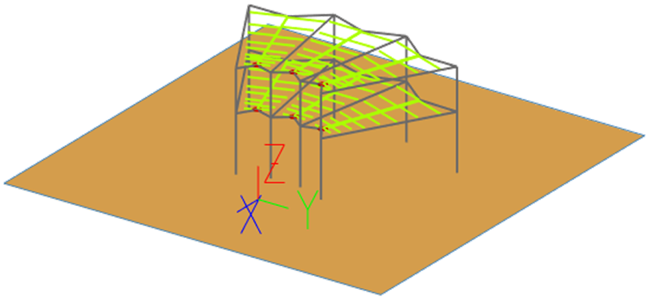
Based on the principle of compactness, this paper tries to reduce the array size as much as possible while meeting the requirements of broadband and high gain. However, the size of shortwave LPDA compared to wavelength should not be underestimated. Considering practical engineering applications, when installing antennas, the structure needs to use rigid support structures to meet sufficient strength. The traditional method generally uses a combination of antenna towers and suspension cables to fix the antenna array, as shown in Fig. 8. A total of 8 support towers are set on both sides of the front and rear ends of each double-layer LPDA. The height of the support towers is higher than that of the upper layer antenna. The front and rear suspension cables are respectively led out from the top or middle of the front and rear support towers to indirectly fix the assembly lines of the upper and lower antennas. Each oscillator is indirectly fixed at both ends by longitudinal side suspension cables in the front and back directions. Usually, in order to enhance the stability of the entire antenna array, each support tower is fixed with suspension cables, occupying a large area. Moreover, when this antenna curtain based on suspension towers and cable tensioning is used as a transmitting/receiving antenna for skywave over-the-horizon radar, it will cause significant vibration of the antenna curtain under strong winds, causing phase modulation of the transmitting/receiving signal, seriously affecting the detection of low-speed targets by skywave over-the-horizon radar. In addition, the cumbersome antenna towers and suspension structures on both sides of each unit antenna can have adverse effects on the radiation performance, and this suspension structure form is also very inconvenient for maintenance operations.
Stay wire-supported structure.

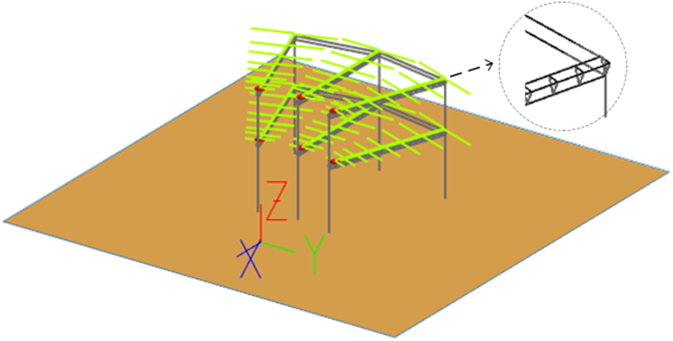
In response to the above shortcomings of the LPDA in suspension structures, this section proposes a new truss type support structure, seeing Fig. 9, including a support tower and a transverse truss beam. To reduce the impact of rigid support towers on the antenna array, the support towers are moved from both sides of the antenna to directly below the antenna array. The transverse beams are arranged directly below the central axis of each group of double-layer antennas, with the front and rear towers at the same height as the upper layer antennas. In order to strengthen the structural strength and reduce the impact on the antenna, the transverse truss beam adopts a trihedral hollow structure. The crossbeam is divided into upper and lower layers to connect the front and rear support towers together, forming a gate-shaped steel structure. The upper and lower crossbeams are installed horizontally, and one pair of horizontal LPDA is installed at an appropriate position directly above them, forming a double-layer LPDA for tower installation. The entire antenna array is equipped with six support towers and six crossbeams, which are divided into three groups to install six pairs of LPDA, forming an inner fan-shaped double-layer LPDAs.
Truss-supported structure.

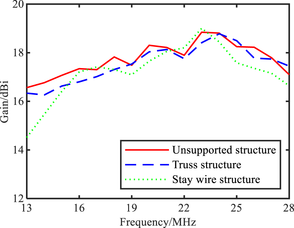
The fan-shaped array Cadfeko model is established with the ideal infinite conductive plane as ground medium, and the balanced-unbalanced converter is used for power feeding. The material of the antenna element is copper, the material of the supporting structure is iron, and all other materials are non-conductive. As the iron support structure belongs to a conductive medium, it will have a certain impact on the electrical and radiation performance. Based on the optimization problems and methods in III (C) and (D), performance optimization is performed on the fan-shaped array under three conditions: unsupported structure (see Fig. 6), stay wire structure (see Fig. 8), and transverse truss structure (see Fig. 9). The VSWR and maximum gain under the above three support structures are shown in Fig. 10 and Fig. 11.
VSWR under (a) unsupported, (b) truss, (c) stay wire structures.

Maximum gain under three different structural conditions.

From Fig. 10 and Fig. 11, it can be seen that under unsupported structures, the fan-shaped array can be optimized to achieve good standing wave ratio and gain characteristics, whose VSWR is ≤2, the maximum gain is ≥16.6 dBi, and the average value is 17.7dBi; Under the transverse truss structure, the fan-shaped array can also be optimized to achieve better standing wave ratio and gain characteristics, VSWR ≤2, maximum gains ≥16.3 dBi, with an average value of 17.5 dBi, which is basically consistent with the unsupported structure; Under the cable structure, the optimized standing wave ratio of the fan-shaped array is only ≤3, the maximum gain is only ≥14.5 dBi, and the average value is 17.1 dBi. The fluctuation of its standing wave ratio and gain characteristics is relatively large, especially in the low and high frequency bands, mainly due to the negative effects of rigid structures such as cables and support towers on both sides of the front and rear end oscillators near these two frequency bands, which deteriorate the electrical and radiation performance of the fan-shaped array itself.
Beam scanning optimization
The LPDA fan-shaped array can obtain the required antenna pattern and beam direction by controlling the feed phase of each element, thereby achieving the beam scanning required by the user. The feed phase selection of the antenna element can be achieved by controlling the phase shifter or delay line group according to the optimized wave control table [Reference Mailloux34, Reference Yang, Li, Wei and Xu35]. For the 2 × 3 element LPDA fan-shaped array proposed in this paper, the feed phase of six elements can be optimized and a wave control table can be established to make the main beam of the antenna array point towards the expected direction while maintaining low sidelobe characteristics. This paper uses the intelligent optimization algorithm ACGOA [Reference Wang, Kang and Li32, Reference Wang, Liu, Wu, Li and Xie36] to optimize the LPDA fan-shaped array pattern, taking the feed phase of each element of the array as the optimization variable, and maximizing the main beam gain and minimizing the maximum sidelobes of the array pattern as the objective functions:
 \begin{equation}{\text{fitness = min}}\left\{ {\sum\limits_{i = 1}^n {\left[ {{A_i}\left( {{G_0} - {G_{{\varphi _0}}}\left( {{\omega _i}} \right)} \right) + {W_i}\mathop {\max }\limits_{\varphi ' \in S} {G_{\varphi '}}\left( {{\omega _i}} \right)} \right]} } \right\}\end{equation}
where  ${G_{{\varphi _0}}}\left( {{\omega _i}} \right)$ and
 ${G_{\varphi '}}\left( {{\omega _i}} \right)$ represent the gains corresponding to the main beam
 ${\varphi _0}$ and the maximum sidelobe
 $\varphi '$ when the frequency is
 ${\omega _i}$,
 ${\omega _i}\left( {i = 1,2,\ldots,n} \right)$ is the i-th operating frequency point, and
 $S$ is the range of sidelobe angles;
 ${G_0}$ is the rated gain;
 ${A_i}$ and
 ${W_i}$ are adjustment parameters that balance the gain characteristics of the antenna’s main lobe and maximum sidelobe. On the one hand, they can maximize the main lobe gain as much as possible, and on the other hand, they can suppress the maximum sidelobe gain as much as possible. Obviously, the smaller the objective function value, the better the optimization effect.
To achieve the maximum scanning range  ${\phi _{\text{m}}}$ of the array,
 $S = \left( {{\varphi _0} + {{{\varphi _{{\text{HP}}}}} \mathord{\left/
{\vphantom {{{\varphi _{{\text{HP}}}}} 2}} \right.
} 2}, {\kern 1pt} 2\pi + {\varphi _0} - {{{\varphi _{{\text{HP}}}}} \mathord{\left/
{\vphantom {{{\varphi _{{\text{HP}}}}} 2}} \right.
} 2}} \right)$ can be taken when the horizontal main beam is pointing towards
 $\varphi {\text{ = }}{\varphi _0}\left( {{\varphi _0} \leqslant {\phi _{\text{m}}}} \right)$ and the beam width is
 ${\varphi _{{\text{HP}}}}$. The feed phases of each array element are optimized to maximize the main lobe gain of the antenna array within
 $[{\varphi _0} - {{{\varphi _{{\text{HP}}}}} \mathord{\left/
{\vphantom {{{\varphi _{{\text{HP}}}}} 2}} \right.
} 2}, {\kern 1pt} {\varphi _0} + {{{\varphi _{{\text{HP}}}}} \mathord{\left/
{\vphantom {{{\varphi _{{\text{HP}}}}} 2}} \right.
} 2}]$, while minimizing the sidelobe gain outside of that interval (i.e., S region) as much as possible. Table 3 presents the optimization algorithm of the fan-shaped LPDA phased array.
Optimization algorithm for fan-shaped phased array

Optimization parameter results of the fan-shaped array

After multiple optimizations, the parameter results of the fan-shaped LPDA phased array are shown in Table 4. Under the three electrical sweep angles, the maximum VSWR are all less than 2.0, and the maximum side lobe levels (SLL) are all less than −12.8 dB, −12.5 dB, and −11.4 dB.
When  ${\varphi _0} = {0^ \circ },{15^ \circ },{30^ \circ }$ is taken separately, the simulation obtained the three-dimensional pattern of the optimized fan-shaped phased array. Figure 12 shows the conditions at the operating frequencies of 17 MHz and 23 MHz. The specific parameters such as beam pointing, maximum gain, beam elevation angle, and beam width at the operating frequencies are shown in Fig. 13. It can be seen that the beam direction at 0°, 15°, and 30° remains basically stable within the operating frequency band; Under different beam directions, the trend of maximum gain variation within the frequency band remains basically consistent, with an average maximum gain of 17.5 dBi, 17.3 dBi, and 16.8 dBi, respectively. There are small differences in the lower frequency range, mainly due to the influence of beam deflection; The 3 dB beam width on the E-plane remains consistent, and the average value within the frequency band is greater than 30°, indicating that the azimuth scanning range of the fan-shaped array can cover at least ± 45° and up to over 90°; The beam elevation angle and H-plane 3 dB beam width vary with the operating frequency between 20°–10° and 22°–10°, respectively, and their changing trends remain consistent in different beam directions.
Three-dimensional pattern of the optimized fan-shaped phased array.

Phase scanning performance of optimized fan-shaped array.

Verification and analysis
Verification model
The partial electrical performance testing of shortwave antennas is difficult to achieve, especially the radiation pattern testing project of shortwave antennas is huge and extremely expensive. Therefore, to verify the correctness of the electrical performance simulation results of antenna arrays, scaled models are generally used for testing. When making a scaled model of the antenna array, the size and supporting structure of the antenna are also scaled down proportionally. Under the conditions of the scaled model experiment, the prototype system is scaled down in a certain proportion to obtain a model antenna that is easy to test. The performance of the prototype antenna can be verified by testing the VSWR and directional pattern of the model antenna. According to the electromagnetic similarity theory, a 1:60 scale model of the fan-shaped phased array is fabricated. The material of the antenna element is copper, the material of the support structure is iron, and the rest are non-dielectric materials. The overall size of the array (including support structure) is approximately 0.7 × 0.46 × 0.17 m3, and the size of the conductive ground is about 4 times that of the array size, as shown in Fig. 14. Performance tests such as directional patterns were conducted in a microwave anechoic chamber by forming a testing system with a signal generator, power divider, and phase shifter matrix, with a testing frequency range of 780–1680 MHz (corresponding to simulation frequencies of 13–28 MHz).
Test environment of 1:60 scaling model of 2 × 3 elements LPDA fan-shaped array with truss structure.

Verification model
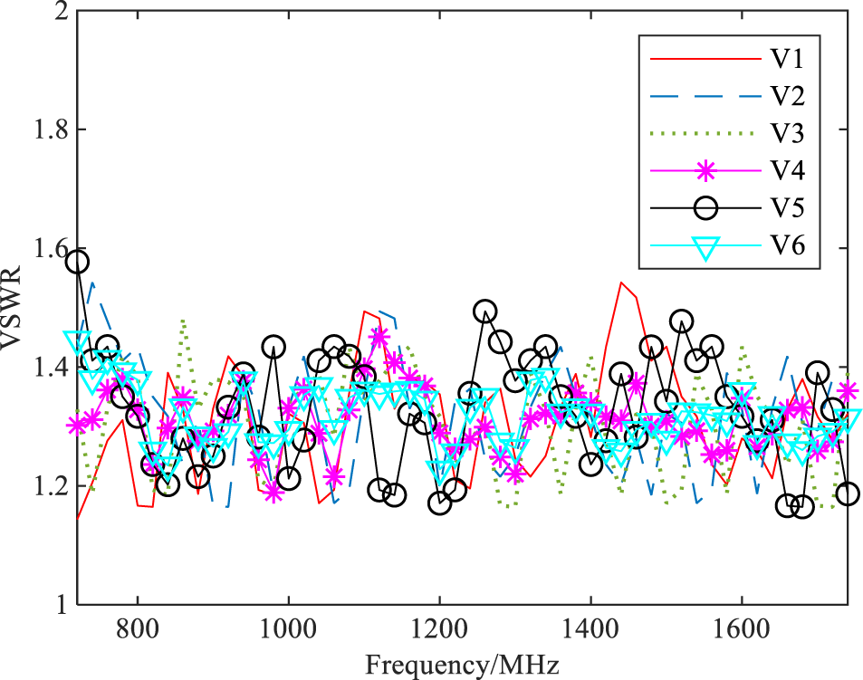
The VSWR of the scaled model unit antenna of the antenna array was tested using a network analyzer. The test results are shown in Fig. 15. In the frequency range of 780–1680 MHz, the VSWR of the model antenna array is less than 2, which is consistent with the simulation results (see Fig. 10). By comparing and analyzing the simulation values in Fig. 10 with the test values in Fig. 15, as shown in Table 5, it can be seen that the test values of the VSWR are generally slightly better than the simulation values, which is because the nonlinearity and loss of the transformer core of the transmission line can smooth out the high capacitive reactance at the antenna input end, greatly improving the standing wave ratio of the antenna.
VSWR test curve of scaling model of LPDA array.

Average test values of VSWR for each element

Radiation characteristics
The pattern of the phased array scaled model was tested in the microwave anechoic chamber. Here, the gain pattern test results of the H-plane and E-plane at a frequency point are presented, as shown in Fig. 16. The test frequency of the model antenna in the figure is 1020 MHz and 1380 MHz, and the corresponding actual simulated frequency is 17 MHz and 23 MHz. It can be seen that under different beam directions  ${\varphi _0} = {0^ \circ },{15^ \circ },{30^ \circ }$, the maximum gains of the fan-shaped array at the test frequency of 1020 MHz are 17.3 dBi, 17.0 dBi, and 16.2 dBi, respectively, and the beam widths of the e-plane are 32°, 32°, and 33°, respectively. the maximum gains of the fan-shaped array at the test frequency of 1380 MHz are 18.9 dBi, 18.1 dBi, and 17.1 dBi, respectively, and the beam widths of the e-plane are 31°, 31°, and 30°, respectively. The test pattern of the model antenna is basically consistent with the simulation pattern of the actual antenna. It is indicated that the proposed 2 × 3-element LPDA fan-shaped array structure and truss-type support structure are feasible, the simulation data are real, and the scale model verification is reliable, which can provide technical support for the research and design of shortwave LPDA phased array.
Test pattern of fan-shaped LPDA phased array.

Conclusion
Starting from the LPDA unit antenna, this paper introduces antenna array technology to establish a 2 × 3 element fan-shaped array structure for the LPDA array. Based on the principles of broadband decoupling and broadband grating lobe suppression, an optimization model for the fan-shaped array is established, and an intelligent optimization method for low coupling fan-shaped arrays is proposed; Using phased array technology, the design of a 2 × 3 element LPDA phased array was carried out, and the mutual coupling effects of antenna and structural parameters on the LPDA phased array were studied to optimize triangular hollow low coupling truss type support structure. Finally, a scaled model for LPDA fan-shaped array with a ratio of 1:60 was produced and verified. The proposed LPDA fan-shaped array has the characteristics of broadband, high gain, and wide scanning, and could be used in fields such as shortwave communication and skywave over-the-horizon radar.
Acknowledgements
This work was supported by National Key R&D Program of China under Grant 2021YFF1500100, National Science Fund for Distinguished Young Scholars under Grant 52025072, National Natural Science Foundation of China under Grant 62401606, and National Key Laboratory Fund of Electromagnetic Energy under Grant 614221724030101.
Competing interests
The authors declare none.

Hengfeng Wang was born in Hunan, China, in 1992. He received a BS degree in communication engineering from Hunan University, Changsha, China, in 2014, and MS and PhD degrees in communication and information system from Naval University of Engineering, Wuhan, China, in 2016 and 2020, respectively. In 2020, he joined the Naval University of Engineering, Wuhan, China, as an assistant research fellow. His research interests focus on array signal processing, antenna and array design, and electromagnetic defense.

Huaning Wu was born in Yichang, China, in 1987. He received MS and PhD degrees in Information and Communication Engineering from Naval University of Engineering, Wuhan, China, in 2012 and 2015, respectively. From 2015 to 2022, he worked as a lecturer in Naval University of Engineering. Since 2023, he has been working as an assistant professor with the Electronic Engineering department, Naval University of Engineering, Wuhan, China. His research interests include antenna theory, underwater radio communication, electromagnetic field, and electromagnetic wave propagation.

Xuebao Wang was born in Hubei, China, in 1991. He received a BS degree in Electronic and Information Engineering at Northeastern Forestry University, China, in 2014. He received MS and PhD degrees in Communication and information system at Naval University of Engineering, China, in 2016 and 2020, respectively. He is now a lecturer in Naval University of Engineering, China. His research interests include radar emitter signal processing and recognition and artificial intelligence.

Jundi Wang was born in Hebei, China, in 1995. He is currently an assistant research fellow in Naval University of Engineering, Wuhan, China. His current research interests include electromagnetic perception, jamming cancellation, and effectiveness evaluation.

Zhi Huang was born in Fujian, China, in 1994. He obtained a Bachelor’s degree in Information Warfare from Hubei Wuhan Naval Engineering University in 2017, a Master’s degree in Circuit and System at Naval University of Engineering in 2020, and a PhD degree in Information and Communication Engineering at Naval University of Engineering in 2023. He is currently employed at the Naval Engineering University. His research interests include motion induced noise suppression, radar interference suppression, and radar signal processing.

Jiahao Zhang was born in Hubei, China, in 1990. He obtained a Bachelor’s degree in Communication Engineering from Huazhong University of Science and Technology in 2012, a Master’s degree in Electrical Engineering from Naval Engineering University in 2015, and a PhD degree in Information and Communication Engineering from University of Leuven in 2019. He is currently employed at the Naval Engineering University. His research interests include electromagnetic compatibility, interference cancellation, and antenna design.