Introduction
Since ideas of the early visionaries like Konstantin E. Tsiolkovsky (1857–1935) and Robert H. Goddard (1882–1945) electric propulsion (EP) has become an absolutely cogent technology (Choueiri, Reference Choueiri2004), which may satisfy the demands for propulsion of many present and future space projects. EP builds on separation of an energy source from a propellant and in this way overcomes the thermodynamic limitation in exhaust speed (Sutton & Biblarz, Reference Sutton and Biblarz2017) that is inherent to combustion and flow dynamics physic. Owing to acceleration of massive ionized particles by electromagnetic fields to speed which is several times higher than the exhaust velocity produced by classic rocket engines, the use of electric thrusters bids a dramatic improvement in the mass budget for orbital and deep space missions. For instance, Hall effect thruster (HET) powered with voltage of 250–300 V typically provides specific impulse I sp (i.e., mean speed of the exhausted particles divided by the Earth gravity g) at the level of about 1600 s (~16 km/s, what corresponds to the average energy of xenon ions of ~175 eV). This value is at least three times greater than I sp produced by the best rocket engines that rely on gas heating due to exothermic chemical reactions. According to the Tsiolkovsky's rocket equation (Goebel & Katz, Reference Goebel, Katz and Yuen2008) the gain in wet to dry mass ratio M r could be equal to  $M_{\rm r}^{1/3} $ for such a HET if the same increase in the rocket speed ΔV is requested for both types of engines. It means that by rising the exhaust speed, one is able to increase significantly the mass foreseen for payload, with all beneficial consequences for the mission, including reduced spacecraft weight and price. Of course, the more detailed analysis indicates that there is an optimum I sp value above which desired ΔV would be again penalized by increased mass ratio (Gulczinski & Spores, Reference Gulczinski and Spores1996). It is a direct consequence of the diminishing power to mass ratio ξ of the whole powering system (including PV panels as well as supply units) which will appear if higher value of I sp is to be requested. Nevertheless, demand for I sp several times greater than that produced due to combustion is almost always rational and stimulates optimization studies on EP offered by different technologies.
HET, like ion gridded thruster (IGT) is regarded to be one of the most matured EP techniques of our days (Mazouffre, Reference Mazouffre2016). As far as stream of expelled mass is concerned, it is worth noting that HET is able to generate electrically compensated ion beam with current density of ~0.1 A/cm2 at the exit plane. It is about ten times more than the value that could be offered by IGTs in which space charge limitation reduces the extracted current density. That makes HET a more compact device than IGT. Moreover, HET usually provides better thrust-to-power ratio what turns it into serious competitor for IGT, despite of the fact that IGT usually produces more than two times higher I sp.
The thruster performance is measured not only by its driving characteristics like thrust T and I sp, but also by propellant utilization and efficiency η. The last factor reflects capability to convert electric power into kinetic energy of the expelled particles. It has been shown that the anode efficiency of xenon HET gains its peak value of ~70% only for the most powerful thrusters like SPT-290, NASA-300M, NASA-400M, and others (Leporini et al., Reference Leporini, Giannetti, Andreussi, Pedrini, Rossodivita, Piragino, Andrenucci and Estublier2016). However, with their size (outer discharge channel diameter of 300–400 mm) and requirements for electric power in the range of 10–30 kW those thrusters could be applicable only for the biggest spacecrafts. Much smaller satellites, with PV panels below 1 kW, need inexpensive HETs of reduced size and power. This is the target group for the relatively small thruster that evolved from the ESA/PECS project entitled Krypton Large IMpulse Thruster – KLIMT (Kurzyna & Szelecka, Reference Kurzyna and Szelecka2016a) and which will be presented in this paper. However, it should be kept in mind that scaling down HET (Ahedo & Gallardo, Reference Ahedo and Gallardo2003; Dannenmayer & Mazouffre, Reference Dannenmayer and Mazouffre2011; Shagaida, Reference Shagaida2015) involves an inevitable drop in efficiency (experimentally found to be at the level of ~40% for the best optimized models of the size comparable with KLIMT) that has to be accepted as a consequence of physical constraints.
Searching for reduction of space mission costs the expenditures that appear due to the use of a specific type of propellant should be also addressed. Despite that xenon is regarded to be an almost perfect propulsive agent for HETs and IGTs owing to high atomic mass, low ionization potential, significant ionization cross-section, and chemical neutrality, its scarcity in the Earth atmosphere as well as permanent growth of demand by more and more propellant-intensive space missions resulted in extremely high price of this noble gas. This issue has inspired a number of investigations geared toward replacement of xenon with less expensive propellant – usefulness of several chemical elements was analyzed, for example, by Kieckhafer and King (Reference Kieckhafer and King2007). One candidate was krypton that is lighter than xenon (83.8 u instead of 131.3 u) and displays a drop in ionization cross-section as well as slightly higher ionization potential (14.0 eV instead of 12.1 eV) what unavoidably qualify it as less efficient propellant. Nevertheless, krypton preserves the noble gas advantages worthwhile for space applications, while its unit price drops below 20% of the cost of xenon. There was a lot of studies to assess the performance of HET supplied with krypton (Kim et al., Reference Kim, Popov, Kozlov, Skrylnikov and Grdlichko2001; Linnell & Gallimore, Reference Linnell and Gallimore2006; Scharfe, Reference Scharfe2009; Nakles et al., Reference Nakles, Hargus, Delgado and Corey2011; Bugrova et al., Reference Bugrova, Bishaev, Desyatskov, Kozintseva, Lipatov and Dudeck2013), to which the current work also belongs. However, unlike most of HET devices which were used to investigate propulsive efficiency of krypton, the presented here Hall thruster was from the outset designed to be fueled with this noble gas as the main propellant (Kurzyna & Daniłko Reference Kurzyna and Daniłko2011).
In this paper, the comparative assessment of KLIMT performance will be presented as measured for both propellants in the PlaNS propulsion laboratory of the Institute of Plasma Physics and Laser Microfusion (IPPLM) in Poland and ESA Propulsion Laboratory (EPL) at ESTEC in the Netherlands.
IPPLM's krypton HET
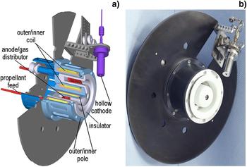
The basic assumptions as well as guidelines to the KLIMT's design were already presented in several papers – see, for example, Kurzyna et al. (Reference Kurzyna, Szelecka, Daniłko, Barral, Dannenmayer, Bosch Borras and Schönherr2016b) and its citations. However, for clarity, salient details will be reproduced below. KLIMT is a laboratory model of HET with an annular discharge channel made of boron nitride ceramics M26. It belongs to the class of plasma accelerators with closed drift of electrons that is known in Russian literature as stationary plasma thruster (SPT) with a magnetic layer or extended acceleration zone (Zhurin et al., Reference Zhurin, Kaufman and Robinson1999). The KLIMT's CAD model cross-section is reproduced in Figure 1a, while a photo of this thruster implementation (third prototype version) in Figure 1b.
KLIMT third prototype version: (a) cross-section of the CAD model, (b) photo of the assembled thruster ready for the measurement campaign.

Due to scaling down from the SPT-100 model known to operate at nominal power of 1350 W (the version that defines the state-of-the-art standard) to the 500 W class HET, the following dimensions for KLIMT were chosen: outer diameter of the discharge channel D out = 50 mm, channel width d ch = 8 mm, and variable channel length L ch = 12–35 mm provided by shifting the anode/gas distributor along the discharge channel axis. The movable anode inside the channel as well as application of convertible magnetic poles of different shapes as well as adjustable position and angle of the cathode with respect to the thruster exit plane were contrived to provide for easier experimental optimization.
Plasma beam is expelled in the exit plane of HET with energies of massive particles up to several hundred eV. It is ejected due to acceleration of ions by the axial electric field E z spanning inside the discharge channel between internal anode and external cathode (see Fig. 1). However, to accelerate the ions, first a gaseous propellant must be introduced to the discharge channel through a large number of micro orifices uniformly distributed at the surface of the anode. (The anode and gas supply functions are often separated as an alternative solution.) When injected into the channel, neutral atoms of the propellant are ionized in collisions with electrons emitted by the cathode and entering the channel. To make a “dense electron target” for neutrals and increase the effectiveness of the ionization, a magnetic barrier is created close to the channel exit plane. The configuration of magnetic circuit provide B-field topography with dominating radial component B r. The electrons from the cathode are subjected to azimuthal drift in the crossed E z and B r fields inside the channel. The trapped (magnetized) electrons can diffuse to the anode owing to collisions with neutrals (and to some extent with walls as well as due to microinstabilities). The ions created in these collisions are accelerated by E z field to energies consistent with the electric potential value in the place of creation. Downstream from the thruster exit plane, the expelled ions capture additional electrons emitted by the cathode and quasi-neutral plasma jet is formed, therefore the thruster stays electrically neutral.
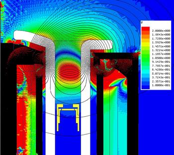
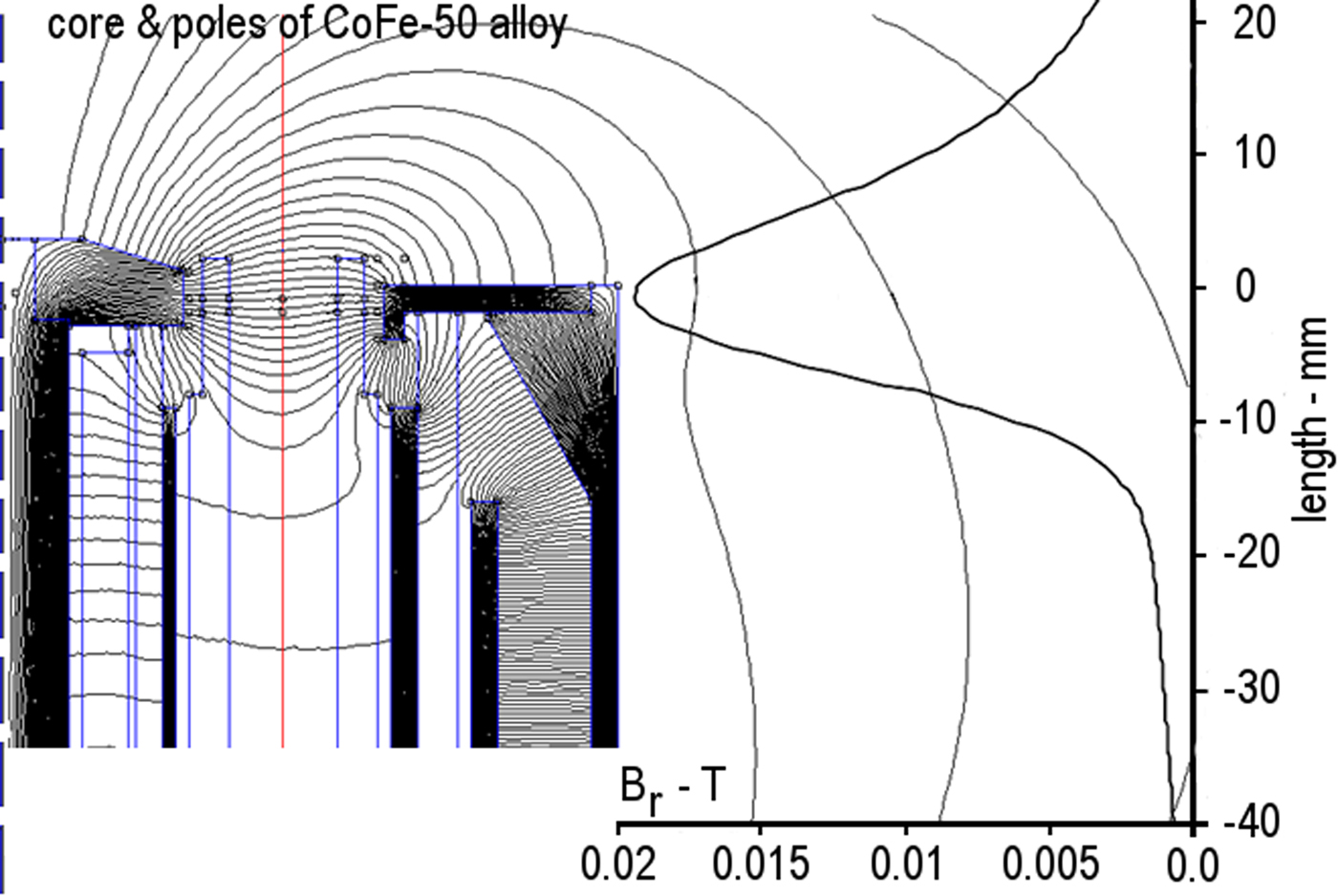
To effectively magnetize electrons and only negligibly influence ion trajectories, the following conditions must be satisfied inside acceleration zone L a: Hall parameter β = ωe/νeh ≫ 1, R Le ≪ L a ≪ R Li where ωe is electron cyclotron frequency, νeh electron-heavy particles collision frequency, R Le and R Li electron and ion Larmor (gyro) radius. During the design phase of KLIMT, it was assumed that the operating power must not exceed 500 W while discharge voltage 500 V. Mass flow rate for krypton as well as xenon was foreseen to be kept below 1.5 mg/s in all experiments, while the maximum value of induction vector B r0(r) [at the channel centerline: r m = (D inn + D out)/4] was planned to be varied in the range 0.01–0.025 T. An exemplary distribution of the magnetic field lines as well as B r component value along the centerline of the channel is shown in Figure 2, for the ratio of the outer coil current I out to the inner coil current I inn equal to 0.5/0.6. The calculations were performed with the use of public domain FEMM solver (Meeker, Reference Meeker2010). For more details, including a temperature effect on B r distribution, the reader is referred to our previous paper (Szelecka et al., Reference Szelecka, Kurzyna and Bourdain2017).
B-field distribution for the second KLIMT prototype version with the core and poles made of Hiperco-50 alloy. I out = 0.5 A, I inn = 0.6 A.
In HET the role of magnetic field is not only trapping the electrons what results in the increased plasma resistance and such axial electric field distribution which effectively accelerates ions in the region of magnetic barrier, but also magnetic lens formation for ion beam focusing. The idea of magnetic lens was supported by the concept of a thermalized potential ΦT = φ + (kT e/e)ln (n e/n 0), where φ represents electric potential, T e and n e electron temperature and number density while n 0 a reference density value (Morozov & Savelyev, Reference Morozov and Savelyev2000). Due to the relation  $\nabla \Phi _{\rm T} = {\bi u}_{\rm e} \times {\bi B}$ thermalized potential must be constant along magnetic field lines. The smaller electron temperature variation along magnetic field lines the better thermalized potential should mimic the equipotential lines which ultimately determine ion trajectories. Focusing topography of B-field improves the thrust vector by reduction of plasma beam divergence and also decreases erosion of the channel walls. The wall erosion will be also reduced if magnetic mirror effect is strong enough to reflect the energetic electrons (Shagaida et al., Reference Shagaida, Gorshkov and Tomilin2012). Nevertheless, relaying on more detailed numerical studies of the electric and thermalized potential distributions in the HET channel, it was shown (Geng et al., Reference Geng, Brieda, Rose and Keidar2013) that there is a big discrepancy between the shape of electric field lines and magnetic field lines in case the magnetic field is strongly non-uninform or/and electron temperature varies significantly along the B-field lines. That is why an experimental adjustments of the magnetic field topography are necessary for better focusing of plasma beam (improving thrust vector) and channel wall protection aiming at optimized thruster, and thus, suggested in Russian literature heuristic G-criterion for optimized topography of B-field builds merely on the outcomes of experiments (Gorshkov and Shagaida, Reference Gorshkov and Shagaida2008). Just this criterion was used for examination of the KLIMT's B-field topography which was designed relying on the SPT-100 magnetic lines distribution. The map of magnetic field lines distribution in KLIMT is reproduced in Figure 3 in which the region of the expected location of the ionization zone, as predicted with the G-criterion formula, is also indicated – please note the red spot inside discharge channel.
Location of the ionization zone in the channel of KLIMT as predicted with G-criterion. Coil currents: I out/I inn = 1/2. Modeling with the commercial ANSYS-Maxwell solver.

Within the KLIMT project, an improvement of the engine design was aimed to be done in three subsequent steps, starting from scratch. Critical assessment of each version performance and identification of its drawbacks provided feedback for the next variant upgrades. One of the issues encountered was the thruster overheating above long-term temperature limitation (500 °C) of the coils that were made of the high-temperature-resistant Kulgrid 28 winding wire (Ceramawire, 2011). The problem has been successfully resolved and the third KLIMT's version (the last one) appeared to be able to operate much below the allowed temperature limit (at least by 100 °C) in the whole range of operating parameters, for as long as it was requested (Szelecka et al., Reference Szelecka, Kurzyna and Bourdain2017).
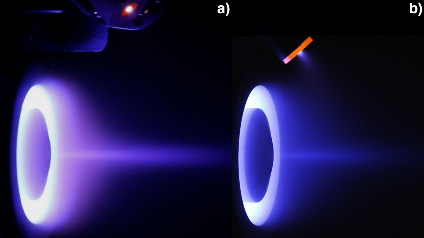
HET should be optimized in tandem with the thruster itself and the cathode. Two types of hollow cathodes were tested during the project: KRI Kaufman&Robinson/BeamTec SHDC1000 heaterless cathode and HWPES-250 HeatWave Labs Inc. cathode with an inner heater. Both models were rated to provide electron current up to 10 A. Despite the fact that the disposable SDHC1000 cathode was able to support stable operation of KLIMT in much wider range of working conditions than the second one, this cathode cumbersome ignition procedure, short lifetime (up to 300 h) and, above all, high gas consumption (comparable with the requirements of the thruster itself) resulted in rejection of this model in further tests. The photos of KLIMT as operated with krypton and both types of cathodes are shown in Figure 4. It appeared that HWPES-250 cathode, when positioned close to the KLIMT's exit plane, provided its stable operation for mass flow rates as low as 10% of the mass flow rate supplied to the anode. However, to reduce discharge current oscillations (suppress spiky mode), the HWPES-250 cathode was also supplied with an increased mass flow rate (up to 20–30% of the thruster mass flow rate) in a sizeable number of tests.
Second KLIMT's prototype operated with krypton: (a) with SDHC1000 cathode, (b) with HWPES-250 cathode. Please note the various cathode locations. Difference in brightness of plasma plume is mainly caused by reduced time of exposure.

In the majority of tests, the HWPES cathode was inclined at an angle of ~80° with respect to the thruster axis, while its orifice was shifted ~10 mm downwind with respect to the exit plane and ~35 mm radially with respect to the thruster axis. This location provided the most reliable thruster operation. However, the cathode body suffered due to the sputtering of radially expanding plasma plume.
KLIMT examination in EPL and IPPLM
In order to assess the performance of KLIMT, thrust produced and angular distribution of ion current carried by the expelled plasma beam were measured. The measurements were performed in a wide range of operating conditions by variation of propellant mass flow rate, discharge voltage and magnetic field topography (due to modification of the values and ratios of currents in the thruster coils). During all the tests, discharge current RMS values as well as temporal discharge current characteristics I D(t) were recorded. Additionally, the cathode's keeper voltage and current, pressure in the vacuum chamber and inside the cathode and anode lines, both coil temperatures, as well as thruster body and radiator temperatures were monitored. Comparative tests were performed for both gases: krypton and xenon; however, beam divergence measurements were carried out only for krypton and only in EPL at ESTEC.
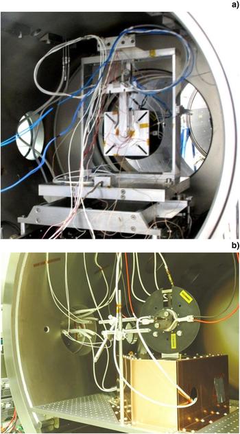
EPL is a certified research entity well known to the European EP community. For description of the EPL's capabilities and equipment, the reader is referred, for example, to the paper by Gonzalez del Amo et al. (Reference Gonzalez del Amo, Saccoccia and Frigot2009). In EPL, KLIMT was tested inside CORONA vacuum facility with total volume of ~17 m3 (main chamber: ~16 m3 and the hatch: ~1 m3). During all the thrust measurements in EPL, KLIMT was fixed to the 1-axis ALTA thrust stand (TS) that was positioned inside the hatch of CORONA facility, just in front of the throat of the main chamber (see Fig. 5). While testing KLIMT, the dynamic pressure inside the chamber varied in the range of 0.6–1.4 × 10⁻⁵ mbar in the main chamber and 1.8–3.8 × 10⁻⁵ mbar in the hatch for the applied Xe mass flow rates. For krypton, the relevant changes of pressure were in the range of 0.4–1.1 × 10⁻⁵ and 1.9–4.7 × 10⁻⁵ mbar. The values are gas-corrected gauge readouts. The ion current measurements were performed for KLIMT positioned inside the main chamber – in these cases the pressures varied in the range of 0.4–1.0 × 10⁻⁵ mbar in the main chamber and 0.34–1.13 × 10⁻⁵ mbar in the hatch.
(a) ALTA 1-axis thrust stand location (with KLIMT attached) inside the hatch of CORONA (EPL) vacuum facility. Thruster exit plane is facing the throat of the main chamber – the gate valve is opened while the main chamber detached. (b) KLIMT as mounted at the MECARTEX thrust stand inside the IPPLM's PlaNS laboratory 2.5 m3 vacuum chamber.

Only the first and the third KLIMT prototypes were tested at ESTEC. Moreover, the relevant measurement campaigns were relatively short and allowed to probe only strictly defined sets of operating conditions. In contrary, the second prototype version was comprehensively tested in the IPPLM's own EP laboratory (PlaNS) that was established in 2013. The volume of the IPPLM's vacuum chamber is ~2.5 m3, while overall pumping speed as measured for the facility equals ~14 m3/s for Xe and ~18 m3/s for Kr. The ultimate pressure in the chamber goes down to ~3 × 10⁻⁸ mbar (N2). During the thruster operation, the background pressure does not exceeded 2.75 × 10⁻⁵ mbar for Xe and 2.85 × 10⁻⁵ mbar for Kr (the values are gas-corrected readouts of the ITR Ionivac 90 Oerlikon/Leybold gauge). More detailed description of the vacuum facility and laboratory equipment, together with power units used to supply the thruster, was provided elsewhere (Kurzyna et al., Reference Kurzyna, Szelecka, Daniłko, Barral, Dannenmayer, Bosch Borras and Schönherr2016b).
The second prototype was tested only in the PlaNS laboratory, where owing to much less restrictive time constraints, detailed examination of the engine was possible that allowed for positive troubleshooting of the encountered issues and removing shortcomings of the design. It resulted in the guidance for the third version improvements. Examination of this last version in the EPL was preceded with a short session in the IPPLM, just to confirm operational readiness of the thruster and select a set of operating conditions to be tested at ESTEC. The measurement campaign in EPL has been complemented with a calibrating post-sessions in the PlaNS laboratory. Finally, when an interface between KLIMT and the Mecartex thrust balance has appeared to be reliable, an additional measurement campaign for absolute thrust measurements was performed also in the PlaNS laboratory. In such a way, the inter-laboratory results could be critically compared.
Using Mecartex’ TS
In the IPPLM, the thrust was measured with the use of a TS designed and manufactured by the Swiss Mecartex company during CE FP7 LμPPT project No. 283279. In principle, it operates like a pendulum suspended at a set of flexures with stiffness compensation. The displacement of the pendulum is proportional to the acting force and can be recorded with high precision. When a thruster is fixed to the TS and subsequently powered on and off, the difference in the relevant pendulum positions is a measure of the thrust.
Because the Mecartex TS design was primarily dedicated for small pulsed plasma thrusters, in the first approach the thrust of KLIMT (a more massive engine) was assessed only in an indirect way (Kurzyna et al., Reference Kurzyna, Szelecka, Daniłko, Barral, Dannenmayer, Bosch Borras and Schönherr2016b). A graphite target with diameter D g = 200 and thickness of 20 mm was fixed on the TS that was positioned 900 mm in front of the thruster. If the plasma beam particles emitted by the thruster were reflected from the target, the target would be displaced proportionally (assuming perfectly elastic collisions) to the momentum flux of these particles. Because the target intercepted only a finite section of the beam and the assumption of elastic collisions was most likely not satisfied, this method could only provide the information about the relative change in performance and in no way absolute values of the thrust T. Several factors that may influence the method that relies on capturing momentum flux of the expelled particles were discussed by Longmier et al. (Reference Longmier, Reid, Gallimore, Chang-Díaz, Squire, Glover, Chavers and Bering2009).
In the second approach, KLIMT was placed directly on the TS with the use of a dedicated support (Fig. 5b). This way, the TS was subjected to the full force of the working thruster and the displacement corresponded to the actual thrust vector. The TS was mechanically calibrated using weights of known masses to calculate the thrust for a given displacement. All the electric and gas lines were led in such a way as to not increase the stiffness of the system which would affect the measurement precision. To this end, the wires were connected at large curvatures, perpendicularly to the direction of movement (except the gas tubes), and fixed to the vacuum vessel to eliminate the influence of the lines’ weight.
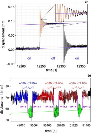
Oscillations of the thrust balance were damped with a voice coil (using PID controlling system) to increase the measurement precision. Because the thruster temperature was increasing during its operation, temperatures of the support and the TS were also rising. This resulted in a change in stiffness of the TS, so calibration measurements could not be used in a straightforward manner of  $T = \Delta x\; k_0^{{\rm cal}} $, where
 $k_0^{{\rm cal}} $ is the stiffness of the TS during calibration.
The stiffness of simple harmonic oscillator k 0 is proportional to the square of its angular frequency ω0. Thus,  $k_0/k_0^{{\rm cal}} = ({\rm \omega} _0/{\rm \omega} _0^{{\rm cal}} )^2$, where superscript “cal” denotes oscillator parameters during calibration, and the measured thrust
 $T = \Delta xk_0 = k_0^{{\rm cal}} ({\rm \omega} _0/{\rm \omega} _0^{{\rm cal}} )^2$. To assess frequency of the oscillations, the solution Aexp (-γ t)cos (ω1t + φ) of a damped harmonic oscillator was fitted to the TS measurements (Fig. 6), where γ is a damping coefficient and ω1 the angular frequency of damped oscillator (ω1 is related to the angular frequency of undamped oscillator ω0 with relation
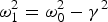 ${\rm \omega} _1^2 = {\rm \omega} _0^2 - {\rm \gamma} ^2$). This correction, done for each measurement separately, allowed to obtain the final values of thrust.
(a) Record of the MECARTEX thrust stand displacement for thrust calculation. Subsequent KLIMT “on-off-on” states are depicted. Fitting with damped oscillator solution for stiffness drift cancelation is shown. The straight lines illustrate a long-term drift of the TS. (b) The relevant ALTA TS record for testing KLIMT at EPL.

Results and discussion: thruster characterization
Plasma engine performance is usually described by thrust T, specific impulse  $I_{{\rm sp}} = T/\dot mg$, thrust to power ratio ξ and efficiency η, where
 $\dot m$ denotes mass flow rate, and g the Earth gravity value. Despite the fact that several very detailed phenomenological models for analysis of Hall thruster efficiency have been proposed – see, for example, Brown et al. (Reference Brown, William Larson, Beal and Gallimore2009), Shagaida (Reference Shagaida2015) and cited there literature – here, the experimentally described anode efficiency
 ${\rm \eta} _{\rm T} = T^2/2\dot mP_{\rm D}$ will be used as an easy to demonstrate characteristics – P D denotes discharge power. Thrust values as measured in both laboratories and RMS of the discharge current were used for performance assessment for each set-point defined by discharge voltage, mass flow rate, and coil currents. Please note that ηT is often factorized into several components that illustrate propellant (mass) utilization
 ${\rm \eta} _{\rm m} = I_{\rm i}m_{\rm i}/e\dot m$, current utilization ηb = I i/I D = I iU D/P D, voltage (energy) utilization ηV = (U D − ΔU)/U D where ΔU describes the average ionization cost, beam divergence ηθ = 〈cos (θ)〉2 that measures the quality of plasma beam focusing and charge utilization ηq that describes the correction due to multiply ionized components of the propellant. Relaying on measurements of the ion angular distribution function (IADF) for the expelled krypton plume, the beam divergence ηθ has been calculated, however, as similar experiment was not performed in the PlaNS laboratory, beam characteristics will not be discussed here in detail.
Given relatively significant heat capacity of the thruster and inefficient cooling (that is provided only by heat radiation), the following routine was applied to avoid inconsistency of results that could appear if the engine performance were measured in transient states (Szelecka et al., Reference Szelecka, Kurzyna and Bourdain2017). During KLIMT operation, temperature of the inner and outer coils were continuously inspected. When they saturated, the thermal equilibrium of the whole thruster was assumed to be reached – usually it required about an hour after the main discharge had been ignited inside the cold thruster channel (in dependence on the initial set-point). Next, TS pendulum displacement was recorded. The first 2 min of the record corresponded to the phase of operating engine, during the next minute the thruster was switched-off, while the last 2 min of the record corresponded to the engine switched-on again with the values of the previous set-point preserved – see Figure 6. Please notice a small change in TS displacement between the first and the second thruster activity cycles resulted from the deviation with respect to the thermal equilibrium during the 1 min pause. In the following step, the operating parameters were varied providing a new set-point and the thruster was left drifting to approach a new thermal steady state. Because in each subsequent step only small variations in the operating parameters were requested, the time needed to equalize KLIMT thermal state was relatively short – usually 7–10 min lasting intervals were long enough. After that period, KLIMT was considered to be ready for the next measurement and the procedure of recording TS signal was repeated. Similar timing scheme was applied in EPL; however, the TS signal was recorded permanently. Thruster operating envelope and corresponding performance was investigated for the range of operating parameters indicated in Table 1. Nevertheless, only the most significant results will be discussed below.
The range of operating parameters

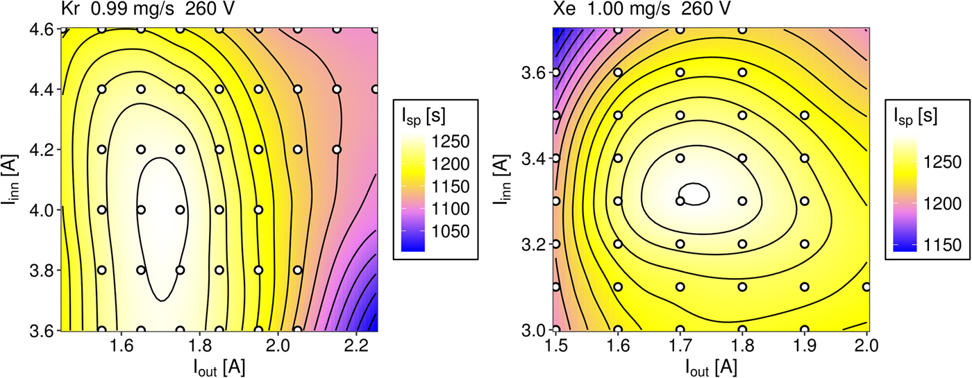
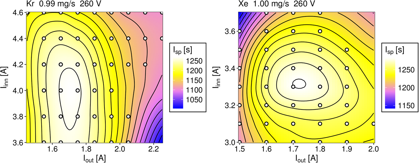
It is worth noting that there are two methods of HET performance examination: (a) when B-field topography is kept constant for the whole set of the operating parameters and (b) adjusting B-field distribution to minimize discharge current value and/or oscillations individually for each set-point. With the use of the second method, one is able to reveal the range of the best thruster efficiency in a more straightforward manner. Searching for the maximum I sp (or thrust) generated by the third KLIMT version for a chosen value of mass flow rate and discharge voltage is illustrated in Figure 7 as a map parameterized with both coil currents. For krypton to generate a maximum I sp, the inner coil current I inn had to be significantly increased in comparison with I inn found to be optimal for xenon. It resulted in shifting the maximum curvature of B-field lines toward the external wall of the discharge channel and producing less symmetric B-field distribution (than is depicted in Figs 2 and 3) with respect to the channel centerline.
Map of I sp as a function of coil currents for the third KLIMT version: (a) for xenon and (b) for krypton.
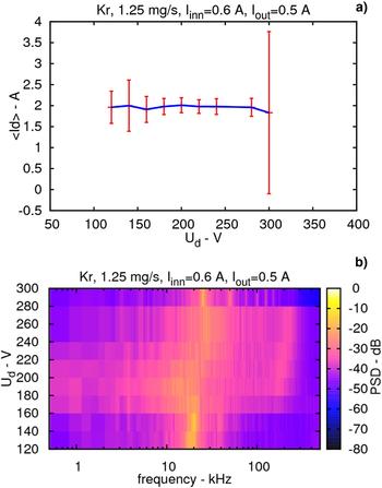
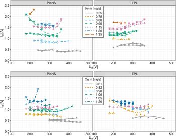
Nevertheless, for KLIMT, it was observed that in the range of moderate discharge voltages, there was no need to adjust B-field topography when it was already optimized for a single set-point. It is illustrated with the current–voltage characteristics reproduced in Figure 8a (for the second KLIMT version). The specified coil currents correspond to the maximum value of B r component equal to ~0.02 T at the channel center line. Figure 8 shows the krypton mass flow rate of 1.25 mg/s and discharge voltage U D within the range of 180–280 V standard deviation of the discharge current σ(I D) ≈ μ(I D)/10, where μ(I D) denotes mean value of the discharge current. The corresponding power spectra (PS) of I D oscillations which represent ionization instability known as the breathing mode (Barral & Ahedo, Reference Barral and Ahedo2009) are broadband and suggest superposition of white noise and harmonic oscillations (Kurzyna e t al., Reference Kurzyna, Gascon, Bonhomme, Dudeck, Makowski, Lago, Lebehot and Peradzynski2002). The locations of the PS maxima shift to higher frequencies if discharge voltage increases. Outside the addressed voltage range, the “quiet” discharge current is replaced with strongly oscillating one and σ(I D) can become comparable with μ(I D) value. In such a case, I D becomes “spiky” with a sharp line of basic frequency and a number of harmonics displayed in the PS – see Figure 8b. For higher values of U D, spiky character of the discharge current could be again significantly reduced or even suppressed due to new adjustment of magnetic field. That typically decreased RMS value of I D (hence discharge power) and prevented reduction in thruster efficiency. Following this observation, the thruster performance was examined in the PlaNS laboratory only for the minimized discharge current RMS value provided by adjustment of coil currents. In Figure 9, RMS discharge current I D is shown as a function of discharge voltage U D for krypton and xenon as measured in both laboratories. In this figure, each symbol corresponds to different coil current values, which were kept constant in the whole range of examined U D within each measurement series. It clearly indicates that optimization of B-field topography reduces discharge current RMS – see, for example, I D–U D characteristics for krypton mass flow rate of 0.95 mg/s for which I D (and so discharge power) can be almost two times bigger (symbol ☒) if the coil currents are not properly matched to operating conditions. Some discrepancy between I D–U D characteristics obtained in both laboratories (especially for low mass flow rates) resulted likely due to less accurate adjustment of coil currents when minimum of RMS value was tracked during measurement campaign in EPL.
(a) Current–voltage characteristics of the second KLIMT version; (b) corresponding power spectra.

Current–voltage characteristics of the third KLIMT prototype as measured in the IPPLM and ESA propulsion laboratories: (a) for krypton, (b) for xenon. Different symbols correspond to different coil current values.

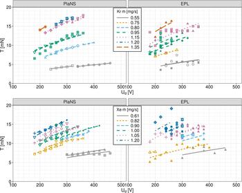
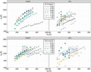
The thrust and I sp as measured in IPPLM and EPL are reproduced in Figures 10 and 11 for both gases. During the experiments, discharge power was not allowed to exceed 500 W. The relevant plots (similarly to I D–U D characteristics) are parameterized with propellant mass flow rate. Symbols correspond to different coil current values. A sqrt type function has been fitted to the measured data sets indicating expected relation between thrust (or I sp) and discharge voltage. The value of standard uncertainty ΔT of thrust was estimated at the level of ±0.8 mN for measurements in EPL (providing a level of confidence ~95%) and ±0.5 mN for measurements in the PlaNS laboratory. However, the results obtained in EPL are more scattered than the outcomes acquired in IPPLM. The analysis of the data sets suggests that in EPL the actual value of ΔT was significantly greater than the calculated uncertainty what could be caused by much higher noise to signal ratio than in the PlaNS laboratory (see Fig. 6). A dispersion of the thrust measurements is reflected by the RMS and variance of residuals between the fitted sqrt(U d) function and the data set, which in EPL are, for instance, respectively, equal to 0.93 and 0.87 mN in case of krypton mass flow rate of 1.15 mg/s and coil current values I inn and I out equal to 5 and 2 A.
Thrust versus discharge voltage as measured in EPL and IPPLM for the third KLIMT prototype: (a) for krypton, (b) for xenon.

I sp versus discharge voltage as measured in EPL and IPPLM for the third KLIMT prototype: (a) for krypton, (b) for xenon.

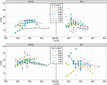
Relying on the measured thrust and RMS values of discharge current, the anode efficiency  ${\rm \eta} _{\rm T} = T^2/(2\dot mU_{\rm D}I_{\rm D})$ was calculated. The results are depicted in Figure 12 for both gases and laboratories. The significant dispersion of the data points is mainly caused by considerable uncertainty ΔT of the measured thrust which must be multiplied by 2 when ΔηT/ηT error is to be estimated by propagation of uncertainties formula (the uncertainty of
 $\dot m,\,\; U_{\rm D},\,{\rm and}\,I_{\rm D}$ are of the secondary importance). Despite the fact that absolute maxima of thrust and I sp for krypton are very close to those as measured for xenon, the top efficiency for krypton is about 10% lower than the anode efficiency for xenon. Similar drop in efficiency was predicted by numerical calculations for KLIMT (Kurzyna et al., Reference Kurzyna, Barral, Daniłko, Miedzik, Bulit and Dannenmayer2014) as performed with the use of HETMAn 1D simulating tool (Barral, Reference Barral and Misuri2012) that was developed relying on the fluid model originated in the Barral's PhD thesis (Reference Barral2003). Please note that in experiments even the best optimized thrusters which operate at high power are known to demonstrate ~5% drop in peak efficiency when supplied with krypton instead of xenon (Kamhawi et al., Reference Kamhawi, Haag, Jacobson and Manzella2011).
Anode efficiency versus discharge voltage as measured in EPL and IPPLM for the third KLIMT prototype: (a) for krypton, (b) for xenon.

The measurements of beam divergence were performed only in EPL and only for krypton. The angular distribution of ion current density j (θ, φ) was recorded with a set of 11 collimating Faraday cups arranged at different angles at the semi-circular arm that rotated (within the range − π/2, π/2) around a vertical axis passing through the symmetry line of the thruster. The experimental set-up and procedure as well as the reconstructed angular distribution function of ions in different operating conditions have been already briefly presented elsewhere (Kurzyna et al., Reference Kurzyna, Szelecka, Daniłko, Barral, Dannenmayer, Bosch Borras and Schönherr2016b). Relying on the measured IADF, the total ion current was calculated by numerical integration according to the formula  $I_{\rm i} = \mathop {\rm \int\!\!\!\int} \nolimits j({\rm \theta,} \,{\rm \varphi} )\sin \,({\rm \theta} )\;{\rm d\theta d\varphi} $, where θ and φ represent polar angles. Subsequently, the beam divergence factor, defined as in the paper of Brown et al. (Reference Brown, William Larson, Beal and Gallimore2009):
 ${\rm \eta} _{\rm \theta} = \left\langle {\cos \,({\rm \theta} )} \right\rangle ^2 = \left( {\mathop {\rm \int\!\!\!\int} \nolimits j\,({\rm \theta,} \,{\rm \varphi} )\,\cos \,({\rm \theta} )\,\sin \,({\rm \theta} )\,{\rm d\theta d\varphi} /I_{\rm i}} \right)^2$ was evaluated giving values in the range of 0.85–0.89 for the whole set of the examined operating conditions (that correspond to the mean half-angle range of ~19°–23°). The obtained results, together with ηm, ηb factors, will be discussed in details in a separate paper.
Conclusion
A relatively small, 500 W class HET (KLIMT) had been developed from scratch and its laboratory implementation has been reviewed. The results of comparative measurements for the KLIMT's performance assessment when the engine was fueled with krypton and xenon propellant has been presented. However, at the very onset of the design process, it was assumed that the primary propellant for KLIMT would be krypton, while xenon should be considered as an alternative and reference propulsive agent. The results show that by tuning magnetic field topography, this HET is able to produce maximum thrust and specific impulse which are close to each other for both gases. Moreover, the outcomes of tests in both laboratories are consistent, although measurements from the PlaNS laboratory exhibit lower dispersion. The thrust and I sp maximum values are in agreement with the data known from the literature for HETs of similar size and power. However, the KLIMT's anode efficiency for krypton propellant drops by about ~10% in comparison with the best results that were recorded for xenon. Further design optimization is predicted to boost the KLIMT's performance. Nevertheless, if there is a need to use a small HET of 500 W, class one has to accept the compromise between performance and inquired thruster dimensions and power. The indisputable advantage of EP engines with performance similar to KLIMT is ability to provide microsatellites/spacecraft with a thruster which is still more efficient in ΔV production than chemical rocket engines.
Acknowledgments
The KLIMT project has been supported by ESA since March 2013 in the frame of the second PECS call (ESA contract No. 4000107746/13/NL/KLM). The development of HETMAn code was partially funded by the European Commission (FP7 “HiPER” project, No. 218859) and received support from the Foundation for Polish Science in year 2011. The project Innovative Liquid Micro Pulsed Plasma Thruster system for Nanosatellites was funded by the European Commission (FP7 “LμPPT” project, No. 283279) and received support from the Foundation for Polish Science in years 2012–2014.