



1. Introduction
Particle-laden flows of a pseudo-plastic fluid, which is a canonical type of non-Newtonian fluid, are widely encountered in industrial and medical applications. For example, concerning the material processing techniques, discontinuous glass or carbon fibres together with the thermoplastics are mostly used to produce a composite material (so-called fibre-reinforced thermoplastics, FRT), and the shell-core microstructure (Tseng Reference Tseng2022) of the flow-induced fibre orientation notably affects the mechanical and thermal properties of such a composite material (Altan Reference Altan1990; Nabergoj, Urevc & Halilovič Reference Nabergoj, Urevc and Halilovič2022). In papermaking processes the alignment and assembly of cellulose nanofibrils (CNF) can greatly improve the overall strength of paper products (Lundell, Söderberg & Alfredsson Reference Lundell, Söderberg and Alfredsson2011; Håkansson et al. Reference Håkansson2014; Boufi et al. Reference Boufi, González, Delgado-Aguilar, Tarrès and Mutjé2017). From a rheology point of view, CNF suspensions generally behave like pseudo-plastic fluids with shear-thinning characteristics (Boufi et al. Reference Boufi, González, Delgado-Aguilar, Tarrès and Mutjé2017). Moreover, in biological areas the bio-fluids, such as blood or respiratory mucus, often display complex rheological properties including viscoelasticity and shear-thinning viscosity (Merrill Reference Merrill1969). The rheological properties of blood are found to be associated with the microstructure of red blood cells (Fedosov et al. Reference Fedosov, Pan, Caswell, Gompper and Karniadakis2011). Understanding the dynamics of spheroids in pseudo-plastic fluids may lead to advances in predicting blood viscosity, which has long been used as an indicator in the treatment of disease (Fedosov et al. Reference Fedosov, Pan, Caswell, Gompper and Karniadakis2011). Therefore, understanding the rotation and orientation of particles in pseudo-plastic fluids is crucial.
The flow-induced orientation of aspherical particles has been extensively studied in Newtonian fluid flows. Jeffery (Reference Jeffery1922) first derived the viscous torques of a spheroid due to the local vorticity and strain rate of Newtonian flow within the Stokesian regime. From the Jeffery torque model, the spheroids retain the initial orientation in a uniform flow (zero vorticity and strain rate) with neglecting the fluid inertial effect in the Stokesian flow assumption. However, in practical situations, the particle-laden flow systems (e.g. ice crystals settling in turbulent clouds (Gustavsson et al. Reference Gustavsson, Sheikh, Naso, Pumir and Mehlig2021), elasto-inertial migration of bio-particles (Lim et al. Reference Lim, Ober, Edd, Desai, Neal, Bong, Doyle, McKinley and Toner2014), the motile micro-organisms swimming in turbulence Qiu et al. Reference Qiu, Cui, Climent and Zhao2022) are usually beyond the Stokesian regime and fluid inertial effect has to be considered. In a flow system with weak fluid inertia ( $\sqrt {R{e_s}} \ll Re \ll 1,\sqrt {R{e_s}}$ is the shear Reynolds number,
 $Re$ is the particle Reynolds number) (Gustavsson et al. Reference Gustavsson, Sheikh, Lopez, Naso, Pumir and Mehlig2019), experimental, theoretical and numerical simulation results have evidenced that the particle orientation is significantly affected by the convective fluid inertia. For instance, in a quiescent Newtonian flow, the slip velocity-induced fluid-inertia torque makes the spheroids tend to settle with the orientation maximizing the drag force. There are several analytic expressions proposed to model such convective fluid-inertia torque for spheroids with small eccentricity (Cox Reference Cox1965) and slender bodies (Khayat & Cox Reference Khayat and Cox1989). Recently, Dabade, Marath & Subramanian (Reference Dabade, Marath and Subramanian2015) used the generalized reciprocal theorem to establish an analytical expression for the fluid-inertia torque. However, the above theoretical models of fluid-inertia torque are restricted to small-
 $Re$ situations. In the case with a finite Reynolds number, the small-
 $Re$ theory generally overestimates the dimensionless fluid-inertia torque (Jiang et al. Reference Jiang, Zhao, Andersson, Gustavsson, Pumir and Mehlig2021). As for the flow system at a finite
 $Re$, numerical simulations are needed to fully resolve the convective fluid inertial effect on spheroid orientation. Sanjeevi, Kuipers & Padding (Reference Sanjeevi, Kuipers and Padding2018), Zastawny et al. (Reference Zastawny, Mallouppas, Zhao and van Wachem2012), Ouchene et al. (Reference Ouchene, Khalij, Arcen and Tanière2016) and Fröhlich, Meinke & Schröder (Reference Fröhlich, Meinke and Schröder2020) analysed the torques of a spheroid in uniform flows with direct numerical simulations (DNS) and proposed several approximate torque parametrizations as a function of particle shape, orientation and
 $Re$.
The above theoretical and numerical studies reveal that the fluid-inertia torque on spheroids has been systematically investigated in Newtonian flows. However, unlike its Newtonian counterpart, the fluid-inertia torque in non-Newtonian fluid flows is not well understood. Different from Newtonian fluids, particle dynamics can be significantly modulated by the peculiar rheology of non-Newtonian fluids. For a prolate spheroid in viscoelastic shear flow without fluid-inertia torque, the particle exhibits multi-orientation modes, including the log-rolling mode, inclined rolling mode in the flow–vorticity plane, bi-stable orientation mode and the flow-alignment mode, with increasing fluid elasticity(D'Avino et al. Reference D'Avino, Hulsen, Greco and Maffettone2014). More interestingly, when the fluid inertial effect is comparable to the effect of fluid elasticity, a new rotation mode, i.e. the asymmetric-kayaking mode, is observed (Li, Xu & Zhao Reference Li, Xu and Zhao2023). In a yield-stress fluid, such as Bingham fluid and elastoviscoplastic fluid, the particle can be trapped in the unyielded region within a certain fluid plasticity (Bingham number  $Bi\sim 2$) (Chaparian et al. Reference Chaparian, Ardekani, Brandt and Tammisola2020). Fluid plasticity is also found to affect the orientation of non-spherical particles in viscoplastic fluids. For example, during the settling of spheroids in a Bingham fluid, particles are surrounded by the yielded envelope and behave in a diagonal motion with an inclined steady orientation (Romanus, Lugarini & Franco Reference Romanus, Lugarini and Franco2022). The above peculiar particle dynamics indicate that the force and torque model of particles in non-Newtonian fluids should account for the effect of fluid rheology. However, a primary obstacle to developing a theoretical model of fluid-inertia torque in non-Newtonian fluids is the high nonlinearity of the constitutive equations. For example, the viscosity in the constitutive model of pseudo-plastic fluids is highly dependent upon the flow shear rate: the larger the flow shear rate is, the lower the apparent viscosity is (the so-called shear-thinning effect).
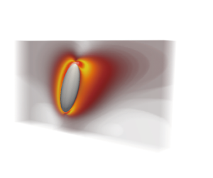
For a spheroid immersed in the pseudo-plastic fluid, the shear-thinning effect can dramatically reduce the apparent viscosity near the particle (figure 1a,b). Consequently, the spatial gradient of viscosity induced by the fluid rheology can modulate the local flow characteristics near the particle and greatly affect the local fluid inertia (characterized by the local particle Reynolds number,  $Re_a$), as shown in figure 1(c). More quantitatively, with the rheological parameters used in figure 1, the zero-shear-rate viscosity-based particle Reynolds number is
 $6$ at far field, but
 $Re_a$ can reach up to
 $30$ due to the shear-thinning rheology. In such a variable-viscosity flow system, a straightforward question is whether and how the viscosity-dependent flow field and induced non-uniform fluid inertial effect can contribute to the deviation of fluid-inertia torque acting on the particle from that in the Newtonian flow system.
A prolate spheroid immersed in a uniform pseudo-plastic flow: (a) contour of normalized apparent viscosity  $1-{\mu _a}/{\mu _0}$, (b) contour of local shear rate, (c) contour of local particle Reynolds number
 $Re_a$.

To understand the effect of shear-thinning rheology on particle dynamics, researchers devoted much effort to determining the particle behaviours in pseudo-plastic fluids with different approaches. For the particle in weakly shear-thinning fluids, the asymptotic analysis has been utilized to obtain the asymptotic solution of the non-Newtonian flow surrounding particles (Datt et al. Reference Datt, Zhu, Elfring and Pak2015; Elfring Reference Elfring2017; Abtahi & Elfring Reference Abtahi and Elfring2019; van Gogh et al. Reference van Gogh, Demir, Palaniappan and Pak2022). Based on the reciprocal theorem and perturbation expansion, Abtahi & Elfring (Reference Abtahi and Elfring2019) proposed an analytical torque model for an inertialess prolate particle immersed in a Stokesian shear flow of a Carreau-type fluid. Their model demonstrates that the particle in weak shear-thinning fluids retains the degeneracy of Jeffery orbits in Newtonian fluids, and the particle rotation rate is slightly attenuated by shear-thinning rheology. However, limited by the small expanding variables required in the perturbation series, the above theoretical methods can not be used to handle realistic fluids with significantly nonlinear rheological features, including strong shear-thinning rheology. Therefore, as an alternative, numerical simulations are applied to analyse the effect of strong non-Newtonian characteristics on the hydrodynamic torque. Domurath et al. (Reference Domurath, Ausias, Férec, Heinrich and Saphiannikova2019) reported that the shear-thinning effect can slightly reduce the rotation rate of the prolate spheroid in the simple shear flow of Carreau fluids. In such flow, since the zero-slip velocity is between the particle centre and local fluid, the particle rotation is mainly determined by the fluid shear effect. For the flow system with the slip velocity, the related studies have mainly focused on the modulation of particle drag force by shear-thinning rheology. Lashgari et al. (Reference Lashgari, Pralits, Giannetti and Brandt2012) and Bailoor, Seo & Mittal (Reference Bailoor, Seo and Mittal2019) indicated that the shear-thinning effect can decrease the drag coefficients significantly for  $Re=10 \sim 40$. More compliantly, if the spheroids can freely rotate, the fluid-inertia torque is expected to play an important role in the particle rotation. Unfortunately, the fluid-inertia torque modulated by the shear-thinning effect has not yet been systematically reported in earlier studies, which motivates the present research.
Moreover, from the aforementioned applied perspectives, it is also of practical importance to uncover the orientation mechanism of spheroids in pseudo-plastic fluids. The peculiar rheological behaviour shown in figure 1(c) implies that, although the zero-shear-rate viscosity-based  $Re$, which is usually utilized to characterize the convective fluid inertia in particle-laden flow systems of pseudo-plastic fluids (Lashgari et al. Reference Lashgari, Pralits, Giannetti and Brandt2012; Alghalibi et al. Reference Alghalibi, Fornari, Rosti and Brandt2020), is small, the shear-thinning rheology can still induce sufficiently large local fluid inertial effect in the vicinity of the particle. However, the above strong local fluid inertial effect does not yet receive sufficient attention. For example, in the studies on predicting fibre orientation in pseudo-plastic fluids during the injection molding process, the flow-induced orientation of fibre-like particles is only determined by Jeffery torques (Bertevas et al. Reference Bertevas, Férec, Khoo, Ausias and Phan-Thien2018, Reference Bertevas, Parc, Phan-Thien, Férec and Ausias2019; Mezi et al. Reference Mezi, Ausias, Advani and Férec2019; Ngo, Nguyen & Oh Reference Ngo, Nguyen and Oh2021; Tseng Reference Tseng2022) without considering the local fluid inertial effect. Whether such local fluid-inertia torque induced by the shear-thinning rheology can modify the fibre orientation in pseudo-plastic fluids is still unclear.
In this work we performed particle resolved direct numerical simulation to accurately determine the fluid-inertia torque acting on spheroids in pseudo-plastic fluids. In particular, we advance the understanding of the effect of shear-thinning rheology on the spheroid orientational and rotational dynamics. These important findings can help us understand the physics of particle dynamics in shear-thinning fluids, more generally, the flows with non-uniform viscosity. More importantly, these results may play a priori role in developing point-particle models in shear-thinning fluid flows.
In summary, concerning the fluid-inertia torque on a spheroid in pseudo-plastic fluid flows, there are several key questions that remain to be answered: does such a non-Newtonian flow with the non-uniform viscosity affect the hydrodynamic torque on spheroids, and if so, how? Furthermore, how does the modulated fluid-inertia torque affect the particle orientation in pseudo-plastic fluids? The present study seeks to address these questions by fully resolving the fluid-inertia torque on the spheroids and their orientation in the pseudo-plastic fluids with different shear-thinning rheology. The work is organized as follows. In § 2 we introduce the mathematical models and numerical methods of resolving the particle in the pseudo-plastic fluids. Then the modulations of fluid-inertia torque by shear-thinning rheology are discussed in § 3. More specifically, a uniform flow past a spheroid is considered to qualify the fluid-inertia torque in pseudo-plastic fluids in § 3.1, and a spheroid in a simple shear flow is utilized to study the coupling effect of fluid-inertia torque and fluid shear torque on particle orientation in pseudo-plastic fluids in § 3.2. Finally, conclusions are drawn in § 4.
2. Methodology
2.1. Governing equations
2.1.1. Shear-thinning fluid flow
In the present study the interaction between the non-Newtonian flow and particle is fully resolved within the framework of the immersed boundary (IB) method. For the fluid phase, the governing equations for incompressible and isothermal pseudo-plastic fluid flows are written as
 \begin{gather} \boldsymbol{\nabla} \boldsymbol{\cdot} \boldsymbol{u} = 0, \end{gather}
 \begin{gather} {\rho _f}\left( {\frac{{\partial \boldsymbol{u}}}{{\partial t}} + \boldsymbol{u} \boldsymbol{\cdot} \boldsymbol{\nabla} \boldsymbol{u}} \right) ={-}\boldsymbol{\nabla} p + \boldsymbol{\nabla} \boldsymbol{\cdot} \boldsymbol{\tau}_v + \boldsymbol{f}_{IB}, \end{gather}
where  $\boldsymbol {u}$ is the fluid velocity,
 ${\rho _f}$ is the fluid density,
 $p$ is the pressure,
 $\boldsymbol {\tau }_v$ is the viscous stress and
 $\boldsymbol {f}_{IB}$ is the forcing term due to the fluid–particle interaction. The viscous stress is determined by the constitutive equation of a generalized Newtonian fluid as
 \begin{gather} \boldsymbol{\tau}_v = 2{\mu _a}\boldsymbol{\mathsf{S}}, \end{gather}
 \begin{gather} \boldsymbol{\mathsf{S}} = \tfrac{1}{2}\left( {\boldsymbol{\nabla} \boldsymbol{u} + {{\left( {\boldsymbol{\nabla} \boldsymbol{u}} \right)}^{\rm T}}} \right), \end{gather}
in which  $\mu _a$ is the apparent viscosity of the generalized Newtonian fluid. Here
 $\boldsymbol{\mathsf{S}}$ is the strain-rate tensor. The apparent viscosity
 $\mu _a$ is determined by fluid types. Herein, the Carreau model is utilized to characterize the rheology of pseudo-plastic fluids. The rheology model of the Carreau-type fluid is
 \begin{equation} {\mu _a} = {\mu _{\rm{0}}}\left\{ {\frac{{{\mu _\infty }}}{{{\mu _{\rm{0}}}}}{\rm{ + }}\left( {1 - \frac{{{\mu _\infty }}}{{{\mu _{\rm{0}}}}}} \right){{\left[ {1 + {{\left( {\varLambda \dot \gamma } \right)}^2}} \right]}^{{{\left( {n - 1} \right)}/ 2}}}} \right\},\quad \dot \gamma = \sqrt {2{{\mathsf{S}}_{ij}}{{\mathsf{S}}_{ij}}}, \end{equation}
where  $\mu _0$ and
 $\mu _\infty$ are the zero-shear and infinite-shear viscosities, respectively,
 $\varLambda$ is the relaxation time of a non-Newtonian fluid and
 $\dot \gamma$ is the shear rate. Here,
 $n$ is the flow index, which characterizes the rheology of the fluid, i.e.
 $n<1$ for a shear-thinning or pseudo-plastic fluid,
 $n=1$ for a Newtonian fluid and
 $n>1$ for a shear-thickening or dilatant fluid. Herein, we mainly focus on the pseudo-plastic (
 $n<1$) and Newtonian (
 $n=1$) fluids. The above model parameters are generally fitted by rheological experiments.
2.1.2. Particle rotation
The particle rotational motion is governed by the following Euler equation:
 \begin{equation} \frac{{\rm d}(\boldsymbol{I}_{p} \boldsymbol{\omega}_{p})}{{\rm d} t} =\oint_{\varGamma_{p}} \boldsymbol{r} \times(\boldsymbol{\tau} \boldsymbol{\cdot} \boldsymbol{n}) \,{\rm d} s. \end{equation}
Here,  $\boldsymbol {I}_{p}$ is the particle moment of inertia,
 $\boldsymbol {\omega }_{p}$ represents the particle angular velocity,
 ${\varGamma _p}$ is the particle surface,
 $\boldsymbol {r}$ is the position vector on the particle surface from the particle's centre,
 $\boldsymbol {n}$ denotes the unit normal vector pointing outwards on the particle surface and
 $\boldsymbol {\tau }$ represents the hydrodynamic stress tensor acting on the particle surface,
 $\boldsymbol {\tau } = -p\boldsymbol {I} + \boldsymbol {\tau }_v$. The integration of
 $\boldsymbol {\tau }$ accounts for the fluid–particle interaction.
The shear-thinning fluid–particle interaction is modelled within the immersed boundary method framework. The momentum forcing term  $\boldsymbol {f}_{IB}$ in (2.2) is used to satisfy the no-slip condition on the particle surface, which is spread from the fluid–particle interaction forcing term
 $\boldsymbol {F}_{IB}$ (Huang, Chang & Sung Reference Huang, Chang and Sung2011),
 \begin{equation} \boldsymbol{f}_{I B}=\oint_{\varGamma_{p}} \boldsymbol{F}_{IB} \delta(\boldsymbol{x}-\boldsymbol{X}) \,{\rm d} s, \end{equation}
where  $\delta$ is the Dirac delta function and
 $\boldsymbol {X}$ denotes the positions of material Lagrangian points distributed on the particle surface. In the penalty immersed boundary method the fluid–particle interaction forcing term
 $\boldsymbol {F}_{IB}$, acting on the particle surface from the fluid, is given as
 \begin{equation} \boldsymbol{F}_{IB} ={-} \kappa \left[ {\left( {{\boldsymbol{X}_{IB}} - \boldsymbol{X}} \right) + \Delta t\left( {{\boldsymbol{U}_{IB}} - \boldsymbol{U}_{LP}} \right)} \right], \end{equation}
where  $\kappa$ is a large penalty constant in the immersed boundary method with
 $\kappa = 10^4$ in the present simulations,
 $\boldsymbol {X}_{IB}$ and
 $\boldsymbol {U}_{IB}$ represent the positions and velocity of the massless counterpart of the material Lagrangian points, respectively,
 $\boldsymbol {U}_{LP}$ denotes the velocity of the material Lagrangian points and
 $\Delta t$ is the time step.
The corresponding dimensionless parameters in a particle-laden shear-thinning flow are summarized as the particle Reynolds number
 \begin{equation} Re = {{UD}/ {{\nu _0}}}, \end{equation}
the shear Reynolds number
 \begin{equation} Re_s = GD^2/\nu_0 \end{equation}
and the local particle Reynolds number
 \begin{equation} Re_a = {{UD}/ {{\nu _a}}}, \end{equation}
where  $U$ is the slip velocity,
 $D$ is the characteristic length of the particle, i.e. the major diameter of the spheroid and
 ${\nu _0}$ is the zero-shear-rate kinematic viscosity of the fluid. In the present simulation the free-stream velocity
 $U$ and particle major diameter
 $D$ are
 $U=1.0$ and
 $D=1.0$, respectively. The fluid inertia is represented by the variation of the zero-shear-rate kinematic viscosity
 ${\nu _0}$. Here,
 ${\nu _a}$ is the apparent kinematic viscosity of the fluid and
 $G$ denotes the shear rate of the flow.
The Carreau number represents the characteristic of the microstructure in a Carreau-type fluid. Figure 2 shows the rheology of a Carreau fluid with different  $Cu$ and
 $\beta$. From figure 2(a), the shear-thinning rheology is significantly enhanced by increasing
 $Cu$,
 \begin{equation} Cu = {{\varLambda U} / D}. \end{equation}
Rheology of Carreau fluid. (a) Effect of  $Cu$ on apparent viscosity. (b) Effect of
 $\beta$ on apparent viscosity.
 $n=0.2$. The shear rate is non-dimensionalized by the characteristic shear rate of the flow problem.

The viscosity ratio is the ratio between infinite-shear and zero-shear-rate viscosities, and defined as
 \begin{equation} \beta={{\mu _\infty}/{\mu _0}}. \end{equation}
Equation (2.13) indicates that the smaller  $\beta$ is, the stronger the shear-thinning rheology is.
The particle aspect ratio is
 \begin{equation} AR=a/b, \end{equation}
where  $a$ and
 $b$ are the polar and equatorial radius of the spheroid, respectively.
2.1.3. Fluid-inertia torque
The fluid-inertia torque is first proposed to model the effect of weak fluid inertia on the particle orientation in Newtonian flows at small  $Re$ (
 $Re\ll 1$). Based on the small-
 $Re$ theory, the fluid-inertia torque on a particle is formulated as (Dabade et al. Reference Dabade, Marath and Subramanian2015)
 \begin{equation} {\left. \boldsymbol{T}\right|_{Re \ll 1}} ={-} \tfrac{1}{2}ReF\left(AR\right)\mu \boldsymbol{U}{\left( {{D / 2}} \right)^2} \boldsymbol{\hat U} \boldsymbol{\cdot} \boldsymbol{p}({\boldsymbol{\hat U} \wedge \boldsymbol{p}}), \end{equation}
where  $\mu$ is the viscosity of the Newtonian fluid,
 $\boldsymbol {\hat U} = {\boldsymbol {U} / {\| \boldsymbol {U} \|}}$ is a unit vector along the ambient flow,
 $\boldsymbol {p}$ is the orientation vector along the spheroid symmetry axis and
 $F(AR)$ is the shape function (shown in figure 3), which indicates the broadside-on mode is the steady state for spheroids in Newtonian flows. Note that the shape function is only for Newtonian fluids. Scaled by the
 ${1/ 8}Re\mu UD^2$, the dimensionless form of fluid-inertia torque reads
 \begin{equation} {\left. {{T^*}} \right|_{Re \ll 1}} ={-}F\left(AR\right)\sin \alpha \cos \alpha. \end{equation}
Here,  $\alpha$ denotes the angle between
 $\boldsymbol {p}$ and
 $\boldsymbol {\hat U}$. From (2.16), the fluid-inertia torque has an angular dependence given by
 $\sin (2\alpha )$, which has been evidenced by theoretical models (Subramanian & Koch Reference Subramanian and Koch2005; Dabade et al. Reference Dabade, Marath and Subramanian2015) and numerical results (Zastawny et al. Reference Zastawny, Mallouppas, Zhao and van Wachem2012; Ouchene et al. Reference Ouchene, Khalij, Arcen and Tanière2016; Sanjeevi et al. Reference Sanjeevi, Kuipers and Padding2018; Fröhlich et al. Reference Fröhlich, Meinke and Schröder2020).
Shape function  $F(AR)$ of spheroids.

In weakly shear-thinning fluids, the relationship between the torque on spheroids and rheological parameters of Carreau fluids can be modelled via the perturbation expansion theorem. In a small- $Cu$ flow of Carreau fluids, when
 $C{u^2}{\tilde {\dot \gamma }_0^2} \ll 1$, considering the leading-order term of the flow field, the torque
 $\boldsymbol {T}$ on the particle is obtained by integrating the stress on the particle surface as (Datt et al. Reference Datt, Zhu, Elfring and Pak2015; Abtahi & Elfring Reference Abtahi and Elfring2019; van Gogh et al. Reference van Gogh, Demir, Palaniappan and Pak2022)
 \begin{align} \boldsymbol{T} = \oint_{{\varGamma _p}} {\boldsymbol{r} \times \left[{-}p\boldsymbol{I}\boldsymbol{\cdot} \boldsymbol{\rm n} + {\left( {1 + \frac{1}{2}\left( {1 - \beta } \right)\left( {n - 1} \right)C{u^2}\tilde{\dot \gamma} _0^2} \right)( {{{{\tilde{\dot{\boldsymbol{\gamma}}} _0} }} \boldsymbol{\cdot} \boldsymbol{\rm n}} )} \right]} \,{\rm d}s + O( {C{u^4}} ), \end{align}
where  ${\tilde {\dot {\boldsymbol {\gamma }}} _0}$ is the leading-order term of the dimensionless shear-rate tensor
 $\tilde {\dot {\boldsymbol {\gamma }}}$, i.e.
 $\tilde {\dot {\boldsymbol {\gamma }}} = {\tilde {\dot {\boldsymbol {\gamma }}} _0} + O( 1 )$. Here
 $\tilde {\dot {\boldsymbol {\gamma }}}={{\dot {\boldsymbol {{\gamma }}} } / {{{\dot \gamma }_c}}}$, and the characteristic shear rate
 ${{\dot \gamma }_c}$ is determined by
 ${\dot \gamma _c} = {{{U}} / {{D}}}$.
From (2.17), considering the fact that the particle rotation rate is reduced in shear-thinning fluids (Abtahi & Elfring Reference Abtahi and Elfring2019), the dependence of the torque on  $Cu$,
 $n$ and
 $\beta$ can be simplified to
 \begin{equation} \left| \boldsymbol{T} \right| \propto 1+\tfrac{1}{2}\left( {1 - \beta } \right)\left( {n - 1} \right)C{u^2}. \end{equation}
In weakly shear-thinning fluids,  $( {n - 1} )<0$ and
 $( {1 - \beta } )>0$; thus, (2.18) reveals that the torque, which the particle experiences in weakly shear-thinning fluids, is positively associated with
 $n$ and the viscosity ratio
 $\beta$, whereas it is negatively associated with
 $Cu$.
In pseudo-plastic fluids with highly shear-thinning rheology, the hydrodynamic torque  $\boldsymbol {T}$ acting on a spheroid needs to be computed numerically as
 \begin{equation} \boldsymbol{T} = \oint_{{\varGamma _p}} {\boldsymbol{r} \times \left( {\boldsymbol{\tau}\boldsymbol{\cdot} \boldsymbol{\rm n}} \right)\,{\rm d}s} ={-}\int_{{\varOmega _p}} {\boldsymbol{r} \times {\boldsymbol{f}_{IB}}} \,{\rm d}v + {\rho _f}\frac{{\rm d}}{{{\rm d}t}}\left( {\int_{{\varOmega _p}} {\boldsymbol{r} \times \boldsymbol{u}} \,{\rm d}v} \right), \end{equation}
where  ${\varOmega _p}$ is the particle region bounded with surface
 ${\varGamma _p}$.
2.2. Numerical methods and validation
In this section the numerical method is first presented and then validated by several benchmarking flow examples, including the cylinder flow of pseudo-plastic fluids and uniform flows of Newtonian fluid and Carreau fluid past a fixed spheroid. The governing equations of Carreau-fluid flow are discretized on the staggered grid using a finite-difference method. For temporal discretization of the momentum and constitutive equations, all terms are integrated in time by the second-order Crank–Nicolson (CN) scheme. For spatial discretization of the governing equations, all terms are approximated by a second-order central difference scheme. With the approximate factorization of the coefficient matrix, discretized governing equations are solved within a projection framework without iteration. The detailed numerical method can be found in Kim, Baek & Sung (Reference Kim, Baek and Sung2002), Pan, Kim & Choi (Reference Pan, Kim and Choi2019), Li et al. (Reference Li, Huang, Xu and Zhao2022) and Li et al. (Reference Li, Xu and Zhao2023). Note that the viscosity field is updated explicitly in the simulation. To suppress the non-physical oscillation induced by the CN scheme, the time step  $\Delta t$ is restricted by the grid Fourier number
 $F{o_{\varDelta } } = {{{\mu _a}\Delta t} / {( {\rho \min {{( {\Delta x,\Delta y,\Delta z} )}^2}} )}} \le 1$.
For the particle solver, the particle rotation (2.6) is solved in the particle frame with the fourth-order Runge–Kutta scheme. The particle orientation is represented by quaternions (Goldstein Reference Goldstein1980), which are updated based on the particle angular velocity.
To evaluate the effects of spatial grid resolution on the numerical results, we simulated a prolate particle ( $AR = 3$) rotating in a shear flow of shear-thinning fluids (
 $Re = 6.0$,
 $Cu =0.5$,
 $n = 0.6$) on three meshes with different spatial resolutions, the results are shown in figure 4. Note that a small domain size of
 $L \times H \times W = 4D \times 2D \times 2D$ is chosen in this test case to save the computational cost. The evolution of the
 $y$ coordinate of the particle symmetry axis calculated on two finer meshes (
 $\varDelta = 1/64D$ and
 $\varDelta = 1/128D$) agree well with each other. This suggests that the present grid resolution (
 $\varDelta = 1/64D$) is sufficient to ensure the accuracy in resolving the particle orientation.
Effect of grid resolution on the particle orientation in shear-thinning fluids.

For the verification of the numerical methods, the present non-Newtonian flow solver is firstly validated by the cylinder flow of the pseudo-plastic fluid. The simulation parameters are consistent with Lashgari et al. (Reference Lashgari, Pralits, Giannetti and Brandt2012). Figure 5 shows that the present numerical method has a good performance for capturing the effects of shear-thinning rheology on the stability of the cylinder wake flow (figure 5a) and the drag force (figure 5b) in the pseudo-plastic fluid. It further evidences that the decreased local viscosity (figure 5c) can destabilize the flow dramatically near the cylinder (a monotonic decrease of the critical Reynolds number with decreasing  $n$, as shown in figure 5a).
Validation by a cylinder flow of a pseudo-plastic fluid: (a) stability of cylinder flow, (b) drag coefficient, (c) relative apparent viscosity contour. Here  $\beta = 0.001,\text{ and } Cu=10$. The reference data are from Lashgari et al. (Reference Lashgari, Pralits, Giannetti and Brandt2012).

The present study focuses on particles in shear-thinning fluids with finite fluid inertia. Thus, we checked the capability of the present numerical method to capture the interaction of particle and shear-thinning fluids. In this test case a fixed sphere is immersed in the Carreau fluids ( $Cu = 1.0$,
 $\beta = 0$,
 $n = 0.5$) at different
 $Re = 5\sim 100$. The comparison results of
 $C_D$ are shown in figure 6. Overall, the calculated
 $C_D$ agrees well with that reported by Daunais, Barbeau & Blais (Reference Daunais, Barbeau and Blais2023). The comparison evidences that the present numerical method can capture the interaction of particle and shear-thinning fluids. Note that the small deviation between the calculated result and reference data at
 $Re = 5$ is due to the smaller computation domain used in the present work to save computational cost.
Comparison of calculated  $C_D$ with the reference results (Daunais et al. Reference Daunais, Barbeau and Blais2023) in Carreau fluids.

Finally, before analysing the shear-thinning effect on the fluid-inertia torque, we first focus on the Newtonian case ( $n=1.0$). Figure 7 shows the fluid-inertia torque on spheroids in Newtonian flow at different
 $Re$. Firstly, the results indicate that the present simulation framework is capable of determining the hydrodynamic torque on spheroids in the flows at different
 $Re$. Similarly with Jiang et al. (Reference Jiang, Zhao, Andersson, Gustavsson, Pumir and Mehlig2021), figure 7(a) shows that the fluid-inertia torque on the prolate spheroid does not change its symmetry angular dependence predicted by the small-
 $Re$ theoretical model even in the flow with obvious fluid inertia (
 $Re = 60$), while this symmetry for the oblate particle is slightly broken at
 $Re = 60$ (figure 7b).
Fluid-inertia torque of prolate (a) and oblate (b) spheroids in Newtonian flow ( $n=1.0$). The filled symbols (square, triangle, circle) denote the present results at
 $Re = 60$,
 $Re = 6$,
 $Re = 0.6$, respectively. Solid lines corresponding to present results are fitted by the cubic spline interpolation. The vertical dashed lines represent the incline angle corresponding to the peak of the fluid-inertia torque on spheroids.

3. Results and discussion
3.1. Fluid-inertia torque in pseudo-plastic fluids
To analyse the effect of shear-thinning rheology on fluid-inertia torque, we numerically compute the hydrodynamic torque on the spheroids immersed in a uniform flow of a pseudo-plastic fluid. In the simulation the particle is located at the centre of a box with the size of  $L\times H \times W = 30a \times 30a \times 10a$. The shear-thinning rheology is characterized by
 $Cu=1.0$ and
 $\beta =0.0$.
Figure 8 shows the comparison of fluid-inertia torque on spheroids in pseudo-plastic ( $n < 1$) and Newtonian (
 $n = 1$) fluids. Firstly, for the prolate spheroid with
 $AR=3$ in figure 8(a,b), it is found that, in both Newtonian and pseudo-plastic fluids, the peak of the fluid-inertia torque on spheroids approximately occurs at the particle inclination angle
 $\alpha ={\rm \pi} /4$. This indicates that the shear-thinning rheology of pseudo-plastic fluids does not significantly alter the qualitative inclination angle dependence of fluid-inertia torque. Regardless of
 $Re$ considered in the present flow system, the function form, i.e.
 $T^* \sim \rm {sin}(2\alpha )$, derived in Newtonian fluids, remains qualitatively correct for the prolate spheroid in pseudo-plastic fluids.
Fluid-inertia torque of prolate (a,b) and oblate (c,d) spheroids in Newtonian flow ( $Cu=0.0, n=1.0$) and pseudo-plastic fluid flow (
 $Cu=1.0, n=0.2$). The vertical dashed lines represent the inclined angle corresponding to the peak of the fluid-inertia torque on spheroids. Solid lines are fitted by the cubic spline interpolation based on simulation results (red circle and black triangle). The open black circle in (d) denotes the numerical simulation results, which fits well with the fitting curve. This indicates that the present fitting curve can accurately reveal the relationship between torque and the particle inclined angle.

Different from the prolate spheroid, the strong fluid inertial effect ( $Re = 60$) brings the asymmetry into the inclination angle dependence of fluid-inertia torque for the oblate spheroid with
 $AR = 1/3$ in both Newtonian and pseudo-plastic fluids. Figure 8(c) shows that the symmetry of fluid inertial torque begins to be slightly broken in low-Re flow. Within the larger-
 $Re$ flow system (figure 8d), the particle inclination angle corresponding to the peak of fluid inertial torque in the pseudo-plastic fluid is pronouncedly larger than that in the Newtonian fluid at the same far field
 $Re$. Such a phenomenon reveals that the shear-thinning rheology enhances the asymmetric characteristic of the fluid-inertia torque on the oblate spheroid. In Newtonian flow at moderate
 $Re$, Jiang et al. (Reference Jiang, Zhao, Andersson, Gustavsson, Pumir and Mehlig2021) indicated that the flow detachment behind the oblate spheroid contributes to the symmetry breaking of fluid-inertia torque. From this point of view, in pseudo-plastic fluids the attenuated apparent viscosity induced by the shear-thinning rheology (see figure 9) leads to an increase of the effective
 $Re$ of the local flow near the spheroid, which results in a more obvious asymmetry of fluid-inertia torque in the pseudo-plastic fluid.
Apparent viscosity contour: (a)  $Re=6$; (b)
 $Re=60$. Here
 $Cu=0.5, n=0.2, \alpha ={30^ \circ }$.

On the other hand, from a quantitative perspective, the magnitude of dimensionless fluid-inertia torque on spheroids is impaired by the shear-thinning rheology as shown in figure 8. This phenomenon is consistent with the theoretical prediction in (2.18). In Newtonian flows, earlier studies have indicated that the dimensionless fluid-inertia torque decreases with  $Re$ (Jiang et al. Reference Jiang, Zhao, Andersson, Gustavsson, Pumir and Mehlig2021). Figure 9 shows that the effective
 $Re$ is increased by the shear-thinning effect. Thus, the dimensionless fluid-inertia torque in the pseudo-plastic fluid is smaller than that in a Newtonian flow. More importantly, figure 8 shows that the deviation of fluid-inertia torque between Newtonian and pseudo-plastic fluids is more significant in low-
 $Re$ flow. This implies that the prefactor in the fluid-inertia torque model of spheroids needs to be modified in the pseudo-plastic fluid flow at small
 $Re$. However, the above effect of shear-thinning rheology on the fluid-inertia torque is usually neglected in the simulations of the practical particle-laden two-phase flow of pseudo-plastic fluids, such as FRT, which may lead to an inaccurate prediction of particle orientation.
3.2. Effect of fluid-inertia torque on particle orientation and rotation
To further elaborate on the effect of the modulated fluid-inertia torque on the particle orientation in pseudo-plastic fluids, we further simulate the rotation of neutrally buoyant spheroids immersed in a linear shear flow of pseudo-plastic fluids. Compared with the uniform flow field presented in § 3.1, the particle behaviour is more compliant under the coupled effect of fluid inertia and fluid shear. The flow configuration investigated in this section is sketched in figure 10. Note that the orientation angle of an oblate spheroid in the present flow configuration larger than  ${\rm \pi} /2$ corresponds to
 $\cos (\theta _{y0}) < 0$. In this study the lower plane is fixed while the upper plane moves with a velocity of
 $(GH, 0, 0)$. The particle centre is fixed at
 $y=1/2H$ but it can freely rotate in all directions. Different from the previous studies on particle rotation in the Newtonian shear flow without particle slip velocity, in the present flow system (figure 10) the finite particle slip velocity is present and induces a fluid-inertia torque on the particle.
Schematic of prolate (a) and oblate (b) spheroids in a linear shear flow of the pseudo-plastic fluid. Here  $\theta _y$ is the orientation angle between the spheroid symmetry axis and the
 $y$ axis.

In the flow configuration with particle translation, the fluid-inertia torque is affected by fluid inertia via the particle slip velocity. However, when keeping the same  $Re$ and
 $Re_G$ in the flow system with and without particle translation, the mechanism governing the particle orientation will be consistent. Therefore, to conveniently tune the particle Reynolds number and elaborate on the fluid inertial effect on the particle rotational dynamics, the particle translation is neglected in this study. In the present simulation the domain size of
 $L\times H \times W = 15 \times 4 \times 4$ is chosen. The aspect ratios of the spheroids are set as
 $AR = 3$ for the prolate spheroid and
 $AR = 1/3$ for the oblate spheroid. The initial orientation of spheroids is set as
 $\theta _{y0} = 0$. The shear rate of the flow is
 $G = 0.5$. The rheological parameters of the pseudo-plastic fluid are
 $Cu= G\varLambda = 0\sim 1.0, \beta =0\sim 0.5$ and
 $n=0.2\sim 1.0$. The particle Reynolds number based on the slip velocity at the particle centre is determined by
 $Re = (1/2GH)D/\nu _0$. The shear Reynolds number is defined as
 $Re_s = GD^2/\nu _0$.
The steady orientation of spheroids in pseudo-plastic fluids is presented in figure 11. Firstly, for the orientation of the prolate spheroid in figure 11(a), similar to the Newtonian flow case ( $n =1.0$), with increasing far field
 $Re$, the orientation angle of the prolate spheroid gradually reduces in the pseudo-plastic fluids (
 $n = 0.2 \sim 0.8$). With the larger effect of fluid-inertia torque, the orientation angle of the prolate spheroid in the pseudo-plastic fluid is less than that in the Newtonian fluid. With a further increase in the shear-thinning rheology (
 $n = 0.4$ decreases to
 $0.2$), the symmetry axis of the prolate spheroid approximately turns to be perpendicular to the streamwise. This means the fluid-inertia torque becomes fully dominant with a strong shear-thinning effect. Moreover, from figure 11(a) it is found that the stronger the shear-thinning effect, the weaker the dependence of the particle orientation on
 $Re$.
Steady orientation of spheroids in pseudo-plastic fluids ( $\beta =0.0, Cu=0.5$). (a) Effect of
 $Re$ on the orientation of prolate spheroid (
 $AR=3$). (b) Effect of the flow behaviour index
 $n$ on the orientation of the prolate spheroid (
 $AR=3$). (c) Effect of
 $Re$ on the orientation of the oblate spheroid (
 $AR=1/3$). (d) Effect of flow behaviour index
 $n$ on the orientation of the oblate spheroid (
 $AR=1/3$).

Figure 11(b) shows the response of particle orientation angle on the varying flow behaviour index  $n$. By comparing the results with different
 $Re$, it can be concluded that the effect of shear-thinning rheology is more significant on the particle orientation in the smaller-
 $Re$ flow. This observation is consistent with the shear-thinning effect on the fluid-inertia torque shown in figure 8(a). In figure 11(b) the results clearly evidence that, by adjusting the shear-thinning rheology, the spheroid in the small-
 $Re$ (
 $Re = 6$) flow of pseudo-plastic fluids can also realize the orientation state occurring in high-
 $Re$ (
 $Re = 60$) flow of Newtonian fluids. This implies that the shear-thinning effect should be considered in the hydrodynamic torque model of spheroids in pseudo-plastic fluids, especially for small-
 $Re$ flows.
Figure 11(c,d) shows the dependence of the oblate particle orientation on  $Re$ and the intensity of shear-thinning rheology (
 $n$). In the flow with a weaker shear-thinning effect (
 $n = 0.8$ and Newtonian fluid
 $n = 1.0$), similar to the prolate spheroids, the oblate particle orientation changes monotonically with increasing
 $Re$ due to fluid-inertia torque. However, in the flow with highly shear-thinning rheology (
 $n = 0.2$ and
 $0.4$), the oblate particle orientation varies non-monotonically with
 $Re$. These findings imply that the oblate particle orientation is determined by the competition between the fluid inertial effect and fluid shear effect in pseudo-plastic fluids. Moreover, figure 11(d) also shows that the critical index
 $n$, which governs the dominant effect in the flow system, decreases with attenuating
 $Re$. Thus, the range of
 $n$, in which the fluid inertial effect is dominant, becomes wider. The above results presented in figure 11 imply that the orientation of the spheroid can be controlled by adjusting the shear-thinning rheology in pseudo-plastic fluids.
To evidence this phenomenon, figure 11(d) shows the orientation behaviour of an oblate particle in shear-thinning fluids with different  $n$. From figure 11(d), similar to the prolate spheroid, the effect of shear-thinning rheology on the orientation of the oblate spheroid is more obvious in smaller-
 $Re$ flow. More interestingly, the steady orientation of the oblate spheroid changes non-monotonically with the shear-thinning rheology. This non-monotonic variation is caused by the competition between the fluid inertial and fluid shear effects, as illustrated below in detail.
From a theoretical perspective, when  $Re \ll 1$, the relative importance of the fluid inertial effects on the dynamics of the flat (
 $AR \ll 1$) disk orientation in Newtonian flow can be estimated by (Sheikh et al. Reference Sheikh, Gustavsson, Lopez, Lévêque, Mehlig, Pumir and Naso2020)
 \begin{equation} \frac{{\left| {{\boldsymbol{T}_I}} \right|}}{{\left| {{\boldsymbol{T}_S}} \right|}} \sim \frac{{{{\left| {\boldsymbol{u} - \boldsymbol{v}} \right|}^2}}}{{\nu \left| {\boldsymbol{\varOmega} - \boldsymbol{\omega} } \right|}}, \end{equation}
in which the differences  ${| {\boldsymbol {u} - \boldsymbol {v}} |}$ and
 ${| {\boldsymbol {\varOmega } - \boldsymbol {\omega } } |}$ are the translational and rotational slip velocities, respectively, and where
 $\nu$ denotes the fluid viscosity. For a steady-orientated particle in the present linear shear flow of pseudo-plastic fluids,
 ${| {\boldsymbol {u} - \boldsymbol {v}} |}$ and
 ${| {\boldsymbol {\varOmega } - \boldsymbol {\omega } } |}$ can be approximated by
 ${| {\boldsymbol {u} - \boldsymbol {v}} |} \sim U= 1/2GH$ and
 ${| {\boldsymbol {\varOmega } - \boldsymbol {\omega } } |} \sim 1/2G_{eff}$, where
 $G_{eff}$ is the effective shear rate. The viscosity
 $\nu$ is replaced by the apparent viscosity
 $\nu _a$. Note that the above estimation of the relative importance between
 $\boldsymbol {T}_I$ and
 $\boldsymbol {T}_s$ can also be obtained by the torque correlations for particles in the finite-
 $Re$ flows (Fröhlich et al. Reference Fröhlich, Meinke and Schröder2020). Then, the ratio of the fluid-inertia torque to fluid shear torque is approximated as
 \begin{equation} \frac{{\left| {{\boldsymbol{T}_I}} \right|}}{{\left| {{\boldsymbol{T}_S}} \right|}} \sim \frac{{{{\left| {\boldsymbol{u} - \boldsymbol{v}} \right|}^2}}}{{{\nu _a}\left| {\boldsymbol{\varOmega} - \boldsymbol{\omega} } \right|}} \sim \frac{{{U^2}}}{{{1/ 2}{\nu _a}{G_{eff}}}}. \end{equation}
Equation (3.2) indicates that the relative importance of the fluid inertial effect is affected by two parameters: apparent viscosity  $\nu _a$ and effective shear rate
 $G_{eff}$. The effect of shear-thinning rheology on the local flow field near the spheroid includes two aspects: (1) increasing the fluid shear rate on the spheroid surface, and (2) decreasing the fluid viscosity. The steady orientation of the particle is determined by the competition between the above two mechanisms. For example, for the oblate particle in the shear flow at
 $Re=60$ in figure 11(d), with decreasing the flow behaviour index
 $n$ from
 $n=1.0$ to
 $n=0.6$, the apparent viscosity is attenuated, as shown in figure 12. The fluid inertial effect is dominant in the flow system. Consequently, the orientation angle of the oblate particle decreases with attenuating
 $n$. However, when
 $n$ is further decreased to
 $n \le 0.6$, the flow boundary layer on the spheroid becomes thinner (Daunais et al. Reference Daunais, Barbeau and Blais2023). This causes a larger fluid shear rate on the spheroid surface, as shown in figure 13. The dominant effect in the flow system is shifted to the fluid shear effect. Therefore, the orientation angle of the oblate particle increases with decreasing
 $n$ within the range of strong shear-thinning rheology (
 $n \le 0.6$).
Apparent viscosity on the oblate spheroid,  $AR=1/3, Re=60$: (a)
 $n=0.2$, (b)
 $n=0.4$, (c)
 $n=0.6$.

Fluid shear rate on the oblate spheroid,  $AR=1/3, Re=60$: (a)
 $n=0.2$, (b)
 $n=0.4$, (c)
 $n=0.6$.

Figure 14 shows the  $Cu$-
 $Re$ phase diagram to distinguish the monotonic and non-monotonic variation of oblate particle orientation with
 $n$. It is found that the parameter region where the oblate particle orientation changes non-monotonically with flow behaviour
 $n$ locates in the parameter space of larger
 $Cu$ and
 $Re$.
The  $Cu$–
 $Re$ phase diagram of the response of the oblate particle orientation to
 $n$.

For the effect of particle aspect ratio, figure 15 shows the plots of  $n$ versus the particle orientation with different
 $AR$. Overall, for different particles, the effect of shear-thinning rheology
 $(n)$ on the particle orientation is similar. In the flow at
 $Re = 6$, particle orientation
 $\cos (\theta _y)$ increases monotonically with attenuating
 $n$ for both prolate and oblate particles. However, the effect of aspect ratio on particle orientation is associated with shear-thinning rheology. For prolate spheroids
 $(AR = 2, 3, 4)$ in the flow with strong shear-thinning rheology
 $(n < 0.6)$, particle orientation changes monotonically with increasing
 $AR$, while non-monotonically in weak shear-thinning rheology
 $(n > 0.6)$. For oblate spheroids
 $(AR = 1/2, 1/3, 1/4)$, the particle aspect ratio has a negligible influence on particle orientation when shear-thinning rheology is significant, i.e.
 $n = 0.2$. In contrast, when
 $n > 0.3$, the effect of the aspect ratio on the orientation of oblate spheroids becomes obvious, and the particle orientation changes monotonically with
 $AR$.
Effect of aspect ratio on particle orientation in shear-thinning fluids,  $Re=6$: (a) prolate spheroid, (b) oblate spheroid.

To further understand the effect of the shear-thinning rheology on particle rotation, figures 16 and 17 show the prolate spheroid ( $AR = 3$) rotation in pseudo-plastic fluids. Figure 16(a) indicates that the angular velocity of the prolate spheroid is reduced by the shear-thinning rheology. Such a reduction of the rotation rate of prolate spheroids in pseudo-plastic fluids is also reported in earlier studies on the simple shear flow without slip velocity (Domurath et al. Reference Domurath, Ausias, Férec, Heinrich and Saphiannikova2019). In the small-
 $Re$ flow condition (figures 16a and 17a), the shear-thinning effect greatly accelerates the particle to reach the equilibrium orientation from the initial orientation. However, when
 $Re$ is moderate (
 $Re = 12$ and
 $24$), the shear-thinning effect destabilizes the local flow near the spheroid. Thus, the spheroid approaches its equilibrium orientation in a damped oscillating way (figures 16b and 17b). In this scenario the amplitude of the particle angular velocity is augmented with the shear-thinning rheology. The results in figures 16 and 17 reveal that, besides the orientation of the spheroid, the shear-thinning rheology can also be used to modulate the rotation characteristic of spheroids in pseudo-plastic fluids.
Rotation rate of the prolate spheroid ( $AR = 3$) in pseudo-plastic fluids: (a)
 $Re=6$, (b)
 $Re=12$, (c)
 $Re=24$.

Orientation evolution of the prolate spheroid ( $AR = 3$) in pseudo-plastic fluids: (a)
 $Re=6$, (b)
 $Re=12$, (c)
 $Re=24$.

The apparent viscosity of pseudo-plastic fluids is significantly affected by two rheological parameters  $\beta$ and
 $Cu$ (figure 2). To estimate the effects of the above two important rheological parameters on the particle orientation, the sensitivities of particle orientation to
 $\beta$ and
 $Cu$ are also conducted as shown in figure 18. Figure 18 shows that the particle orientation changes monotonically with
 $\beta$ and
 $Cu$. Moreover, the smaller
 $\beta$ and
 $Cu$, the more significant the effects of the rheological parameters are. Within the parameter range of small
 $\beta$ and
 $Cu$ considered in figure 18(a,b), compared with
 $\beta$, the particle orientation is found to be more sensitive to the factor
 $Cu$ (or the relaxation time
 $\varLambda$). This observation reveals that it is more important to guarantee the measurement accuracy of
 $\varLambda$ in the rheological experiment of the particle suspension of pseudo-plastic fluids. Moreover, figure 18(b) indicates that there exists a critical Carreau number
 $Cu_{cr}$, beyond which the orientation of the prolate spheroid is independent of
 $Cu$ and the fluid inertial torque becomes fully dominant in the flow system.
Effect of rheological parameters on prolate spheroids,  $AR = 3, Re=6$: (a) viscosity ratio,
 $\beta$; (b) Carreau number,
 $Cu$.

Finally, figure 19 shows the dependence of the orientation of the prolate particle ( $AR=3$) on
 $Cu$. By comparing the particle orientation in the flow with different
 $n$, we find that there are two critical Carreau numbers in the present flow system. The first critical Carreau number
 $Cu_{cr1} = 0.01$ represents the starting point, beyond which the effect of shear-thinning rheology on the particle orientation becomes important. More interestingly, the second critical Carreau number
 $Cu_{cr1} \sim O({10^6})$ implies that, when
 $Cu>O({10^6})$, the particle orientation is again independent of
 $n$. From figure 19 it can be concluded that the dependence of particle orientation on the parameter
 $Cu$ can be divided into three regimes: (i) the first Newtonian regime (
 $Cu<0.01$), (ii) the shear-thinning regime (
 $0.01< Cu < O(10^6)$) and (iii) the second Newtonian regime (
 $Cu > O(10^6)$).
Effect of Carreau number on the orientation of the prolate spheroid,  $AR = 3$.

4. Conclusions
In this work we numerically investigated the fluid-inertia torque on a neutrally buoyant spheroid immersed in pseudo-plastic fluid flows. The shear-thinning rheology is described by the Carreau model. The interplay between particle and pseudo-plastic fluid is fully resolved by the immersed boundary method. Firstly, the influence of shear-thinning rheology on the fluid-inertia torque is analysed in the uniform flow. Then, the modulations of the spheroid orientation and rotation by the shear-thinning effect are also studied within the linear shear flow with particle slip velocity. The main conclusions are as follows.
(i) In the flow at moderate
 $Re\sim O(10)$, the shear-thinning rheology enhances the asymmetry of the fluid-inertia torque on the oblate spheroid. Compared with the Newtonian fluid, the magnitude of the dimensionless fluid-inertia torque on spheroids is attenuated by the shear-thinning rheology. The deviation of fluid-inertia torque between Newtonian and pseudo-plastic fluids is more significant in a small-$Re$ flow. This observation indicates that the theoretical model of fluid-inertia torque of spheroids needs to be modified in pseudo-plastic fluid flow at small $Re$.
(ii) Within the range of parameters considered in the present study, the effect of shear-thinning rheology on the orientations of prolate and oblate spheroids are different: the orientation angle of the prolate spheroid decreases monotonically with the flow behaviour index
$n$. In contrast, due to the competition between the fluid inertial and fluid shear effects, the orientation of the oblate spheroid changes non-monotonically with the flow behaviour index $n$. Additionally, the comparisons of the responses of the particle orientation to $n$ in different $Re$ flows indicate that the effect of shear-thinning rheology is more significant on the particle orientation in smaller-$Re$ flows.(iii) The angular velocity of the prolate spheroid is reduced by the shear-thinning rheology. Once the local fluid inertia induced by the shear-thinning rheology is beyond a threshold value, the shear-thinning effect destabilizes the local flow in the vicinity of the spheroid and, thus, the spheroid approaches its equilibrium orientation with damped oscillations.
(iv) The orientation of the prolate spheroid changes monotonically with two rheological parameters, i.e. viscosity ratio
$\beta$ and Carreau number $Cu$. Within the parameter range of small $\beta$ and $Cu$, the orientation of the prolate spheroid is more sensitive to the parameter $Cu$.


In summary, the main contributions of the present work are: (1) a first attempt to numerically elaborate on the fluid-inertia torque on spheroids in pseudo-plastic fluids, and (2) to illustrate the effect of shear-thinning rheology on the spheroid orientational and rotational dynamics induced by the modulated fluid-inertia torque in pseudo-plastic fluids. The results of the present study shed new insights into the fluid-inertia torque in pseudo-plastic fluids. Furthermore, from the applied perspective, the present results could also be potentially useful for designing the rheology-based controlling strategy for guiding particles to realize specific orientations in complex fluids in the future.
Funding
The authors are grateful for the support of the Natural Science Foundation of China through grants nos. 92252104 and 91752205.
Declaration of interests
The authors report no conflict of interest.



