I. INTRODUCTION
Due to the characteristic of the hexagonal crystal lattice, magnesium alloys have the limited number of slip systems, which result in the poor formability at room temperature. And the crystallographic texture always forms upon mechanical processing and leads to a pronounced anisotropy of the mechanical properties of magnesium alloys.Reference Avery, Hosford and Backofen 1 – Reference Gehrmann, Frommert and Gottstein 4 Possible deformation mechanisms in Mg alloys include basal slip, prismatic slip, pyramidal slip, and several twinning modes, and this anisotropy is further reflected in the polarity of {10-12} twinning, which only allows shear in one direction rather than opposite directions.Reference Christian and Mahajan 5 Meanwhile, twinning mechanism has a significant effect on mechanical properties of the wrought Mg alloys. Under certain loading conditions (i.e., tension parallel to the c-axis of the crystal lattice or compression perpendicular to the c-axis), {10-12} twinning will dominate deformation and lead to a relatively low yield stress at the early stages of deformation.Reference Yi, Davies, Brokmeier, Bolmaro, Kainer and Homeyer 6 – Reference Choi, Kim, Kim and Park 10 And strengthening mechanisms related to {10-12} twinning also play an important role in improving mechanical properties of materials.Reference Murr, Moin and Greulich 11 – Reference Lou, Li, Boger, Agnew and Wagoner 14
Due to the polarity characteristic, twins can disappear or become narrower under reverse loading or reloading. This process is referred to as untwinning (or detwinning). Untwinning behavior has been extensively investigated over the past years.Reference Lou, Li, Boger, Agnew and Wagoner 14 – Reference Kleiner and Uggowitzer 17 Untwinning is considered as the reverse process of twinning and is different from twinning in some respects. First, it is the process without twinning nucleation; second, the activated stress required for untwinning is less than that for twinning nucleation but greater than that for twinning growth.Reference Partridge 18 In this study, we investigated the mechanical behavior and the microstructural evolution of Mg alloy containing {10-12} twin lamellar structureand analyzed the effects of twinning strengthening and “untwinning strengthening” on the mechanical properties of materials. High strain rate could enhance the activation of {10-12} extension twinning dramatically.Reference Dudamell, Ulacia, Gálvez, Yi, Bohlen, Letzig, Hurtado and Pérez-Prado 19 , Reference Jiang, Jonas, Mishra, Luo, Sachdev and Godet 20 So to facilitate twinning, dynamic plastic deformation (DPD) was used to achieve predeformation of samples.
II. EXPERIMENTAL METHOD
A. Initial microstructure of material
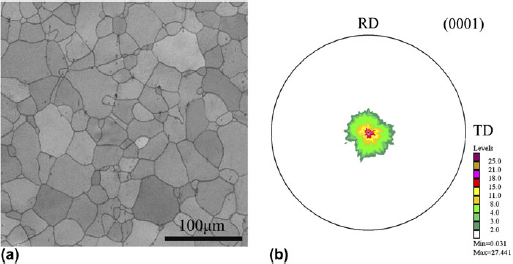
The hot-rolled AZ31 Mg alloy sheet (Mg–3% Al–1% Zn) has twin-free equiaxed grain structure [Fig. 1(a)] and an average grain size of 34 μm evaluated by linear intercept method. As generally observed in annealed AZ31 sheet, the basal {0001} planes of the sheet are aligned almost parallel to the rolling plane, as shown in Fig. 1(b).
Microstructural characteristics of the as-rolled material: (a) EBSD micrograph and (b) (0001) pole figure. RD and TD represent the rolling direction and the transverse direction, respectively.

B. DPD treatment
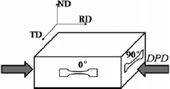
Parallelepiped [30 × 30 × 22 mm in rolling, transverse, and normal directions (RD, TD, and ND), respectively, as shown in Fig. 2] was cut from the hot-rolled AZ31 sheet. Samples were subjected to DPD just once with Instron Dynatup 8120 testing machine (Instron Corporation, Norwood, MA) at room temperature. The loading direction (LD) is parallel to the RD. The strain rate applied in each impact was estimated to be about 103/s. The deformation strain was defined as ε = ln(L 0/L d), where L 0 and L dare the initial and final height of the samples, respectively. Tests were interrupted at strains of 1%, 3%, and 7%.
Schematic illustration of the sample orientations used for DPD and subsequent tensile testing. RD, TD, ND, and LD represent the rolling direction, the transverse direction, the normal direction, and the loading direction, respectively. The arrows indicate the DPD direction.

C. Tensile tests
At room temperature, quasistatic tensile tests were performed in the predeformed AZ31 samples up to failure and to 6%, using SHIMADZU AG-X10KN machine (Shimadzu Europa GmbH, Duisburg, Germany) at an averaged strain rate of 10−2/s. Tensile tests were performed in dog bone-shaped tensile samples with a gage length of 5 mm and a width of 1.26 mm. All samples were manually ground and polished before deformation. The predeformed samples are tested along two directions, with the tensile axis parallel to the predeformed direction and the initial TD (i.e., perpendicular to the predeformed direction), referred to as 0° and 90° respectively, as illustrated in Fig. 2.
D. Microstructure characterization
The initial texture was measured by x-ray diffraction in a Rigaku D/max-2500 PC (Rigaku, Tokyo, Japan). Scanning electron microscopy–electron backscattered diffraction (SEM–EBSD) was utilized to analyze the microstructure and texture of samples before and after deformation. EBSD scans were performed by FEI Nova400 FEG-SEM (FEI Company, Hillsboro, OR) on an area of 300 × 300 with a step size of 1 μm and EBSD information was acquired with Channel 5 software. The samples for EBSD were prepared by standard metallographic polishing and then electropolished using the commercial AC2 electrolyte for 60 s at 20 V and 20 °C.
III. EXPERIMENTAL RESULTS
A. Flow curves
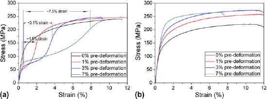
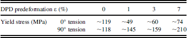
Figure 3 shows the stress–strain curves of predeformed samples corresponding to 0° and 90° tensile tests. It can be seen that the tensile stress–strain behavior of Mg alloy was highly anisotropic due to the presence of texture. The predeformation caused a significant drop in 0° tensile yield stress but led to a significant increase of yield stress during 90° tension. The yield stress of each predeformed sample drastically increased with prestrain, as shown in Fig. 3.
Typical tensile flow curves of AZ31 samples with and without precompression deformation: (a) 0° tension and (b) 90° tension.

B. Microstructural evolution of predeformed AZ31 samples during tensile test
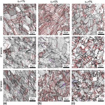
The evolution of microstructure and texture of predeformed AZ31 samples during 0° and 90° tension are presented in Figs. 4 and 5. Each tensile test was stopped at a strain of 6% to analyze the microstructure evolution of the AZ31 alloy after tension and avoid stress relief caused by fracture.
EBSD micrographs illustrating the microstructure evolution of predeformed AZ31 samples after 0° and 90° tension: (a) εDPD = 1%; (b) εDPD = 3%; and (c) εDPD= 7%. The red lines, pink lines, and blue lines indicate {10-12} twin boundaries, {10-11} twin boundaries, and {10-11}–{10-12} twin boundaries, respectively.

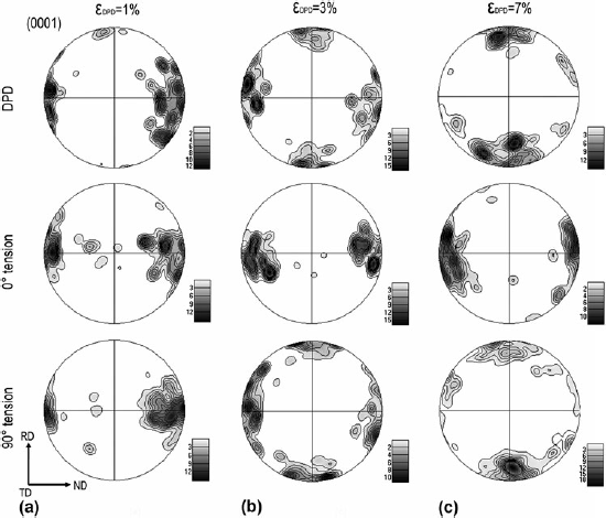
EBSD micrographs illustrating texture evolution of predeformed AZ31 samples before and after 0° and 90° tension: (a) εDPD = 1%; (b) εDPD = 3%; and (c) εDPD= 7%.

1. 0° tensile test
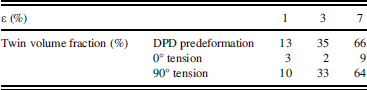
{10-12} twinning was activated by the compression perpendicular to the c-axis of hcp lattice or tension parallel to the c-axis, leading to an 86.3° rotation of c-axis in the twin, which brings them into almost parallel to the LD (Figs. 4 and 5). The difference of twinning textures can be interpreted based on the different volume fractions of {10-12} twins. As shown in Fig. 5 and Table I, the density of twinning texture increased significantly with prestrain. When 0° tensile test was performed in predeformed samples, most of {10-12} twin boundaries disappeared, and the twin volume fractions decreased significantly, as listed in Table I. Obviously, 0° tension led to untwinning of predeformed AZ31 alloy. This can also be seen from Fig. 5, where the basal texture was recovered by untwinning. Due to the loading condition, a few {10-11} compression twins and {10-11}–{10-12} double twins were generated in grains.
Twin volume fractions of predeformed AZ31 alloys.

Tensile properties of predeformed AZ31 alloys.

2. 90° tensile test
As shown in Fig. 4, there remain a large number of {10-12} twins in grains after 90° tension. As listed in Table I, the twin volume fractions of three samples had little change after tension. But a few {10-11} compression twins and {10-11}–{10-12} double twins were generated during tension. Judging by the similar texture type before and after tension (Fig. 5), {10-12} twins made a little contribution to the plastic strain. When tensile direction is parallel to the basal plane, nonbasal slip and {10-11} twinning are activated at the early stages of deformation.Reference Agnew and Duygulu 21 , Reference Keshavarz and Barnett 22
IV. DISCUSSION
A. Effect of {10-12} twin lamellae on 0° tensile plastic deformation
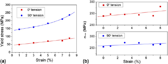
The effect of {10-12} twin lamellae on the stress–strain curve of the as-rolled AZ31 alloy during subsequent 0° tension is illustrated in Fig. 3(a) and Table II. It can be seen that the {10-12} twin lamellae caused a significant drop in tensile yield stress. The concave up curve revealed characteristics of twinning deformation,Reference Caceres and Blake 23 but the twin volume fraction decreased significantly after tension, as listed in Table I, suggesting that {10-12} twinning caused by predeformation was recovered by untwinning during subsequent tensile deformation. For the 1% and 3% predeformed samples, most of {10-12} twin boundaries disappeared after tension, and the presence of a few {10-11} compression twins and {10-11}–{10-12} double twins led to the low twin volume fraction of 3% or 2% (Table I). A high density of residual twins in the 7% predeformed sample resulted from insufficient tensile strain of 6%, which is less than prestrain of 7% [0° tension in Fig. 4(c)]. The tensile yield stress increased slightly with prestrain (Table II) was correlated with the strengthening mechanisms of {10-12} twinning, especially the texture hardening, which was caused by the texture change attributable to untwinning.Reference Lou, Li, Boger, Agnew and Wagoner 14
The present hot-rolled AZ31 Mg alloy provided an initial texture, which favors {10-12} twinning when compression loading is perpendicular to the ND. Due to the activity of {10-12} twins, the c-axis of twins in the predeformed samples would be oriented nearly parallel to the LD (DPD pole figures in Fig. 5). These twinned regions are capable of untwinning during subsequent 0° tension. Untwinning, as a reverse process of twinning, can also lead to an inflected and concave strain hardening behavior.Reference Kleiner and Uggowitzer 17 Meanwhile, the strain caused by twinning in predeformation can be reversed by untwinning.Reference Wang and Huang 16 As shown in Fig. 3(a), it can be seen that the strain intervals between yield point and the concave-shaped end for predeformed samples correlated well with the prestrained value. Excess strain might be generated by crystallographic slip at quasistatic deformation. At low strains, crystallographic slip is limited due to the sample orientation. At larger tensile strain, when twinning is nearly exhausted, slip dominates plastic deformation and a concave down curve appears until elongation to failure.Reference Ball and Prangnell 24 Meanwhile, the complicated interaction between {10-12} twinning and slip leads to an increment of work hardening, which will restrict further deformation and cause sample fracture.
B. Effect of {10-12} twin lamella on 90° tensile plastic deformation
From Fig. 3(b), the stress–strain curve shows an obvious characteristic of slip-dominated deformation, and there remain many twins in grains after 90° tension (90° tension in Fig. 4). The approximate value of twin volume fraction before and after tension suggested that {10-12} twins were not activated during tension. The tensile yield stress increased significantly with prestrain (Table II) was strongly correlated with the strengthening mechanisms of {10-12} twinning, especially the hardening contributions of twins as obstacles to slip.Reference Lou, Li, Boger, Agnew and Wagoner 14
In general, prismatic slip plays an important role when tensile loading is perpendicular to the c-axis of lattice. Basal slip, which has a very low value of critical resolved shear stresses in Mg alloys,Reference Agnew, Yoo and Tome 25 , Reference Barnett 26 will also play a certain role in the early stage of tensile plastic deformation.
C. Comparison of deformation characteristics between 0 and 90° tension
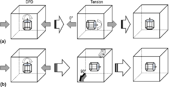
As mentioned above, {10-12} twin lamellae have influenced remarkably on subsequent tensile plastic deformation. The operation of different deformation mechanism, which resulted from the different angles between the tensile loading and the c-axis of crystal lattice, caused the in-plane (RD–TD) anisotropy in the flow stress, as shown in Fig. 3. From Fig. 6(a), since {10-12} twinning led to a reorientation of 86.3° of the crystal lattice, the c-axis of twinned regions was nearly parallel to the 0° tensile direction, so {10-12} twins resulted from predeformation were reversed by untwinning during 0° tension. The tensile yield stress increased slightly with prestrain. Here, the texture hardening, which was caused by the texture change attributable to untwinning, was the main strengthening mechanism of twinning.
Schematic drawings showing the change of orientation due to twinning and untwinning during (a) 0° tension and (b) 90° tension.

For 90° tension, the volume fraction of {10-12} twins was not significantly affected by reloading because the tensile direction was perpendicular to the c-axes of both grain matrix and twinned regions, as shown in Fig. 6(b), restraining {10-12} twinning activity. Thus, nonbasal slip and {10-11} twinning were activated at the early stages of deformation. The tensile yield stress increased significantly with prestrain. Here, the hardening contribution of twins caused by the dislocation pileups developing at the twin boundaries and the sessile dislocations within twins was the main strengthening mechanism.
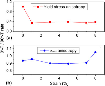
For samples without predeformation, the similar values of yield stress were obtained after 0° and 90° tension (Table II) because nonbasal slip dominated plastic deformation. For predeformed samples, the yield stress for 90° tension was higher than that obtained during 0° tension, and in-plane anisotropy in the yield stress became obvious. But {10-12} twin lamellae had little effect on the maximum flow stress σmax, which was influenced by crystallographic slip. As shown in Fig. 7(b), the maximum flow stress values had changed little with increasing prestrain. Stress ratios, including yield stress ratio and σmax ratio under different tensile loading, were calculated with the aim of analyzing the in-plane anisotropy of mechanical properties. Figure 8 illustrates the variations in yield stress and σmax with increasing prestrain in 0° and 90° tensile tests. As shown in Fig. 8(a), for samples without predeformation, the tensile yield stress was isotropic in RD–TD plane due to the same texture, i.e., tension is perpendicular to the c-axis of crystal lattice. For predeformed samples, the response of tensile properties was highly anisotropic in RD–TD plane, mainly because of the texture change caused by {10-12} twinning. By contrast, the in-plane σmax anisotropy was not obvious and the similar flow stress ratio of about 1 were obtained for different predeformed strain [Fig. 8(b)], suggesting that {10-12} twin lamellae had little effect on the maximum flow stress.
Variation of the yield stress (a) and the maximum flow stress σmax(b) with predeformed strain increasing.

Variation in in-plane yield stress anisotropy (a) and the maximum flow stress σmax(b) with increasing predeformed strain. 0°-T and 90°-T represent 0° tension and 90° tension. respectively.

V. CONCLUSIONS
The aim of this work was to investigate the effects of {10-12} twinning on the mechanical behavior and the microstructural evolution of the as-rolled AZ31 Mg sheet having an intense basal texture, which favors {10-12} twinning after DPD perpendicular to the c-axis of crystal lattice. The main conclusions of this study are listed below.
-
(i) When tension is carried out along the predeformed direction (i.e., 0° tension), untwinning caused a significant drop in yield stress. And {10-12} twinning, which resulted from predeformation and the twinning strain, was also recovered by untwinning. The tensile yield stress increased slightly with prestrain was correlated with the texture hardening, which was caused by the texture change attributable to untwinning.
-
(ii) The volume fraction of {10-12} twins was not significantly affected by subsequent 90° tension because the tensile loading was perpendicular to the c-axes of both grain matrix and twinned regions, restraining the {10-12} twinning activity. Thus, nonbasal slip was activated and dominated plastic deformation. The tensile yield stress increased significantly with prestrain was strongly correlated with the hardening contributions of {10-12} twins.
-
(iii) {10-12} twin lamellae led to the obvious yield stress in-plane anisotropy but had little effect on the maximum flow stress.
ACKNOWLEDGMENTS
This work was supported by National Natural Science Foundation of China (Grant Nos. 51071183, 50890170, and 51271208) and the Fundamental Research Funds for the Central Universities (Grant No. CDJXS11132225).