1. INTRODUCTION
Nearly 40 years ago Stiny and Gips (Reference Stiny and Gips1972) introduced shape grammars as a generative approach to shape design. A few years later, Stiny (Reference Stiny1980a) further detailed this concept and subsequently distinguished set grammars as a simple variant of shape grammars (Stiny, Reference Stiny1982). Since then, a significant amount of research has been done on shape or set grammars, both of which can be classified under the more general term “spatial grammars” (Krishnamurti & Stouffs, Reference Krishnamurti and Stouffs1993). Originally presented for paintings and sculptures, this concept has also been successfully applied in other domains, such as architecture, industrial design, decorative arts, and engineering. Several authors, for example, Chau et al. (Reference Chau, Chen, McKay, de Pennington and Gero2004) and Cagan (Reference Cagan, Antonsson and Cagan2001), provide overviews of existing spatial grammars. However, most of the grammars that have been developed exist only on paper; just a small minority have been computationally implemented. Of those that have been implemented, many are restricted to one specific design domain or application example. Further, the majority of implemented examples do not provide for a visual way to edit an existing grammar or to develop a completely new grammar. Instead, they usually require coding of grammar rules in textual form (Chase, Reference Chase2002), making at least some programming knowledge necessary. Practicing designers, however, tend to think spatially. They are used to working in a graphical environment, for example, using the graphical user interface of a computer-aided design (CAD) system, or are often not willing or able to program due to limited programming experience. Instead, they want to focus on designing.
Recent research activity, especially in the area of two-dimensional (2-D) grammars, shows a growing interest in creating more flexible and interactive, spatial grammar systems. These provide the grammar user with the possibility to not only apply rules, but also to design and change rules (e.g., Jowers et al., Reference Jowers, Prats, Lim, McKay, Garner and Chase2008; Trescak et al., Reference Trescak, Esteva and Rodriguez2009). To date, there is only one known three-dimensional (3-D) implementation that supports a more flexible development of rules from scratch by visually designing the geometric objects (Li et al., Reference Li, Chau, Chen and Wang2009a, Reference Li, Chen, Wang and Chau2009b).
Especially in 3-D space, where spatial thinking is more demanding, it is important to have direct visualization of the rules as they are developed. Without direct visualization, the designer must first write code, and possibly compile it, to see whether the intended geometric objects and spatial relations are generated. The definition of a new grammar also “often tends to be a ‘generate and test’ cycle” (Chase, Reference Chase2002). As a new grammar is often tested and modified several times before it describes the intended design language, this demands proper user support not only for the development of rules, but also for their application.
The aim of the research presented in this paper is the development of a new approach for creating a general 3-D spatial grammar system. Instead of being exclusively created for a specific example or domain, the more general system presented provides a flexible platform supporting designers with visual, interactive definition and application of their own grammar rules in a familiar CAD environment without programming. It supports defining nonparametric and parametric rules, matching the left-hand side (LHS) of a rule under translation and rotation transformations in an existing design and correctly applying the rule.
The paper is written from a mechanical engineering perspective, with the aim of providing design support through the integration of a spatial grammar interpreter into a CAD system. Therefore, comparisons to CAD are drawn and the prototype implementation is based on a 3-D solid CAD system. This reflects a statement by Gips (Reference Gips1999), who describes the idea of developing a shape grammar plug-in for a traditional CAD program that would assist in creating a shape grammar, which in turn, would help the practicing designer.
In this paper the term visual is used to distinguish from grammar approaches that require programming for the development of new rules. The direct visual manipulation of displayed geometric objects with the computer mouse is only possible to a limited extent, for example, to translate and rotate objects. The extent to which direct visual manipulation is possible is highly dependent on the CAD system used and only marginally affects the actual approach. As is common in mechanical engineering design, the need to define parametric relations and exact measurements is realized using numerical inputs that trigger an immediate update of the geometry and its visualization.
The paper starts with a background section that introduces the set and shape grammar formalism, explains the meaning of interpreters and presents relevant existing implementations. Next, it discusses the challenges involved in creating a general, 3-D spatial grammar interpreter. Following, the approach taken in this paper, starting with the concepts for developing nonparametric as well as parametric grammar rules, is presented. The paper then describes the procedure for matching the LHS of a rule in a current design and replacing it with the right-hand side (RHS) based on the calculation of the spatial relations between the involved geometric objects. The main aspects of the prototype implementation are then presented, followed by three illustrative examples. The paper ends with a discussion of the benefits and limitations of the presented approach as well as future work.
2. BACKGROUND
2.1. Terminology and formalism
Spatial grammars is a general term that includes all kinds of grammars that define languages of shape, for example, string grammars, set grammars, graph grammars, and shape grammars (Krishnamurti & Stouffs, Reference Krishnamurti and Stouffs1993). This paper focuses on set and shape grammars because the presented approach is based on a set grammar formulation, and among the related existing implementations, there are also several shape grammar systems. The formalisms of set and shape grammars are similar. Both are generative systems that generate shapes applying defined rules iteratively starting from an initial set or shape that exists within a defined vocabulary of shapes. A set grammar is formally defined as G = (S, L, R, I), where
• S is a finite set of shapes,
• L is a finite set of labels,
• R is a finite set of rules, and
• I is the initial set, where I is a subset of (S, L)0.
The set of labeled shapes, including the empty labeled shape, is (S, L)0 and is also called the vocabulary. The rewriting rules are defined in the form A → B, where A and B are both subsets of the vocabulary. To apply a rule to a given set of labeled shapes, called the working shape C, first, A in the LHS of a rule has to be detected in C. This matching process can make use of valid Euclidean transformations, t, that are applied to A, to find more possible matches of A in the working shape C. The transformed subset A is then subtracted from C and the transformed subset B of the RHS of the rule is added, thus resulting in a new set of labeled shapes C′ where C′ = C – t(A) + t(B).
The formalism of shape grammars is basically the same, where I is the initial shape, A and B are shapes in the vocabulary and rules apply to subshapes of labeled shapes to produce other labeled shapes. In comparison, set grammar rules apply to subsets of sets of labeled shapes to produce other such sets (Stiny, Reference Stiny1982). Therefore, designs generated by a set grammar consist of shapes in S. Designs defined by shape grammars, instead, consist of shapes and subshapes of shapes in S, because the compositional units in designs can be decomposed and recombined in different ways (Stiny, Reference Stiny1982). Shape grammars work directly on spatial forms (Krishnamurti & Stouffs, Reference Krishnamurti and Stouffs1993), whereas set grammars treat designs as symbolic objects with geometric properties, which makes them more amenable to computer implementation (Stiny, Reference Stiny1982). Strictly speaking, a shape grammar involves the use of a maximal line representation, which can be broken down and rerepresented in a large number of ways. For example, a line can be broken up into smaller line segments to form subshapes. This ability for rerepresenting shapes in a number of ways enables for wider matching of the shape A in the LHS of a rule to embedded subshapes in the working shape C.
Krishnamurti and Stouffs (Reference Krishnamurti and Stouffs1993) point out that certain kinds of set grammars could be treated as graph grammars. Based on a set grammar formulation, the approach presented in this paper also includes a few aspects similar to graph grammar approaches. For this reason, the more general term spatial grammar is used throughout this paper.
2.2. Grammar interpreters
Gips (Reference Gips1999) provides a general definition of shape grammar interpreters, calling them a “program for shape grammar generation.” According to Chase (Reference Chase2002), “the complete process of generating a design with a grammar involves two main stages”: the development of the grammar and its application. For increased usability, many existing interpreters focus on the application of rules. However, a generalized interpreter that provides for facilitated use of grammars without programming must support the tasks in both stages (development and application) in an interactive, visual manner. These tasks include, for example, the design of the vocabulary and the rules, the selection of a rule to be applied, the determination of an object, or set of objects, to apply the rule to, as well as calculating transformations and the application of the rule.
2.3. Spatial grammar implementations
To date, only a few spatial grammar systems have been computationally implemented. Nearly all of these have been developed in academia as experimental prototypes or for educational purposes. An overview of implemented systems up until 2002 can be found in Chau et al. (Reference Chau, Chen, McKay, de Pennington and Gero2004). During the last 15 years an increasing interest in implementing more general systems, which can provide user support for both the development and the application phase, can be seen. To date, the majority of these systems are 2-D systems. GEdit (Tapia, Reference Tapia1999) allows for the visual development of rules as well as their interactive application, which includes subshape recognition. New shapes based on straight 2-D lines can be created in an external drawing program and are converted to a maximal line representation once they are imported to GEdit. Shaper2D (http://designmasala.com/miri/shaper2d/; McGill & Knight, Reference McGill and Knight2004) was implemented for educational purposes and allows for the direct visual manipulation of two shapes that are either rectangle, square, isosceles triangle, or equilateral triangle by changing size, location or orientation. A maximum of two rules are iteratively and fully automatically applied where the resulting design is shown in real time. Most recent research makes an effort to extend on interpreters that can also handle curvilinear 2-D shapes. McCormack and Cagan (Reference McCormack and Cagan2006) presented an interpreter that is able to match curve-based shapes, including parametric shape recognition. The focus of this system is not on the definition or modification of grammars, but on the application and, especially, the matching of the LHS of rules in a current working shape. Jowers implemented a shape grammar interpreter, QI, for shapes based on quadric Bézier curves (Jowers & Earl, Reference Jowers and Earl2010, Reference Jowers and Earl2011). New rules can be visually designed by defining or manipulating the positions of the curves' control points. The system automatically detects the LHS of a rule under similarity transformations and includes subshape recognition. The SubShapeDetector (http://www.engineering.leeds.ac.uk/dssg/downloads/requestForm.php), also developed by Jowers et al. (Reference Jowers, Prats, Lim, McKay, Garner and Chase2008), allows for the import of hand-drawn sketches that act as the basis for the interactive development and application of rules. It includes a pixel-based approach for the detection of subshapes, enabling the use of curved shape grammars. The second version of this system, SD2 (http://www.engineering.leeds.ac.uk/dssg/downloads/requestForm.php; Jowers et al., Reference Jowers, Hogg, McKay, Chau and de Pennington2010), in addition, provides for the direct computerized drawing of shapes within the software and the definition of an arbitrary number of rules. A system with a similar range of functionality, but restricted to straight lines and using maximal line representation for subshape detection, was published by Trescak et al. (Reference Trescak, Esteva and Rodriguez2009; http://sourceforge.net/projects/sginterpreter/).
Up to now, only a few implementations of 3-D grammars exist, and the ones that do exist are mainly designed to deal with specific or restricted problems. Therefore, the rules, or rule schemata, are preimplemented using programming or scripting languages. Genesis is currently the only known commercially used implementation of a spatial grammar system and consequently can be considered very mature. It was implemented at Boeing (see, e.g., Heisserman et al., Reference Heisserman, Mattikalli and Callahan2004) based on the original system that Heisserman developed in his PhD thesis to generate, for example, alternative Queen Anne houses, Sierpinski sponges, and fractal-like mountains (Heisserman, Reference Heisserman1994). At Boeing it is used to support the development and interactive application of rules for tubing designs in aircrafts, but generally speaking, it is not restricted to this application area and could work in different domains. It enables designers to explore solution spaces as well as to evaluate, compare, and merge design alternatives. Rather than as replacement rules, that is, replacing the match to the LHS of a rule with the RHS, the design rules are formulated through logical match conditions and design transformations. The geometric objects as well as the rules are implemented upfront for later use by designers. Piazzalunga and Fitzhorn (Reference Piazzalunga and Fitzhorn1998) used a commercial solid modeling kernel to develop an interpreter. In this interpreter the rules are defined using a programming language that makes most of the kernel's capabilities accessible. The application of these rules requires user interaction, where the user chooses a rule and an object to apply the rule to. Chau et al. (Reference Chau, Chen, McKay, de Pennington and Gero2004) presented an approach that can handle rectilinear and curvilinear basic elements in 3-D space. The shapes and rules are created and edited in an external text file and applied to generate wire frame models.
In addition to the systems described so far, a few 3-D implementations provide limited capabilities to customize rules. However, they do not allow for new rules to be defined without programming. The rules are realized as preimplemented rule schemata to which the user can assign specific values. The sizes of shapes and their spatial relations, as well as the number of rule applications, can be defined before the application of a rule; the rule application itself is executed automatically. Wong and Cho (Reference Wong and Cho2004) started from the concept of Shaper2D (see above) and extended it to simulate 3-D blocks into a single rule. In the revised version of this system, Shape Designer V.2 (Wong et al., Reference Wong, Wang, Chen and Yin2005), the user can choose from several different predefined rule schemata. A rule is applied by typing a short command into a text input window. Commands consist of a short name for the chosen rule schema and the required values for the parameters. Depending on the rule schema, these include some or all of the following: number of iterations, translations, rotations, scale factor, and sizes. The 3DShaper (Wang & Duarte, Reference Wang and Duarte2002) provides a dialog window for a preimplemented rule schema to define the sizes and the spatial relationships of two blocks by typing in the required values. In doing so, one or two additive rules are specified that are immediately applied and saved in data files. A visual representation of the rules, as well as of the generated design, is available after opening the created files in an external viewer.
The latest prototype implementation of a grammar system that provides capabilities for the (re)definition of rules, Grammar Environment (Li et al., Reference Li, Chau, Chen and Wang2009a, Reference Li, Chen, Wang and Chau2009b), is based on the system by Chau et al. (Reference Chau, Chen, McKay, de Pennington and Gero2004) but extends it with the capability to define new shapes and nonparametric rules in a graphical environment. The application of rules generates wire frames, like the original system by Chau et al. (Reference Chau, Chen, McKay, de Pennington and Gero2004), however, is restricted to the use of points and straight lines. 2-D shapes and rules can be directly created in the Grammar Environment system, but for the design of 3-D shapes an external shape editor is needed. For this purpose, the commercial CAD system AutoCAD is used. The data of the designed geometry can be imported to the Grammar Environment system to be used for rule definition and application.
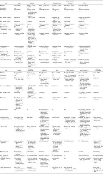
Table 1 presents an overview of the characteristics of the most recent spatial grammar implementations relevant to this paper. Their relevance was determined by their 3-D capabilities and/or the possibility to visually define and modify rules. The data was gathered from published papers and system tutorials, by testing a working copy of the corresponding implementation or in direct correspondence with the authors.
Overview of related spatial grammar implementations

Note: 2-D, two-dimensional; LHS, left-hand side; 3-D, three-dimensional; RHS, right-hand side; CWS, current working shape; CAD, computer-aided design; Reference, one of the latest publications about the implementation; Dimension(s), dimension of the space in which the shapes/rules are used; Shape types, types of shapes that are used in the given rules or that are provided in the implementation for the definition of rules, for example, some systems provide straight lines to define other, more complex shapes and others are restricted to a given set of predefined shapes; Max. number of shapes, maximum number of shapes that can be used in the definition of a rule or that are given in a rule schema; Max. number of rules, maximum number of rules that can be defined in a grammar, where some systems are preimplemented rule schemata that are restricted to a certain number of rules; Rule format, the types of rules the implementation supports/provides, which can be “additive” if only part of the RHS equals the LHS, “subtractive” if the RHS equals only part of the LHS, or “replacing” if the complete LHS is substituted by the RHS; Parametric rules, depicts whether the implementation uses or allows for the definition of parametric rules as described in Stiny (1980a); Definition/editing/manipulation of rules, depicts the means of user interaction for the definition of new rules, editing existing rules, or the manipulation of rule schemata; LHS matching, characterization of how the LHS (shapes and transformations) of a rule is matched in the CWS; Transformations for matching, the kinds of transformations that can be used to find matches of the LHS in the CWS; Application mode, the level of human intervention required or allowed in application steps, for example, the selection of a rule or an object to which a rule is applied; Max. number of applications, some implementations are restricted to a certain number of rule applications (or iterations); One single, integrated system, some implementations require external systems, for example, for the definition of new shapes or to view generated designs; Unique characteristic(s), characteristics that can only be found in the corresponding implementation.
3. CHALLENGES
Using programming for the development of rules and their application provides high flexibility for the implementation of various geometry or vocabulary, especially in expressing relations between, or constraints on, geometric objects. However, as described in the introduction, programming in a design environment has several drawbacks. An interactive visual approach has to provide a set of standard commands whose functionality works on a higher level than programming, but visually usable via a user interface, therefore making it easier to work with. The interplay of the different single commands needs to provide high flexibility to enable a generalized design and use of grammars.
In that regard, specific challenges arise, especially in conjunction with a 3-D approach. Being the basis for the definition of a grammar, the vocabulary should be as flexible as possible to allow for the creation of a wide variety of geometric objects. For the definition of rules, these geometric objects have to be graphically represented to allow for direct manipulation and positioning in 3-D space. The latter requires the robust handling of 3-D transformation operations, at least for translation and rotation. For the application of a rule, the location and orientation of the objects have to be defined in a way that enables the automatic matching of the LHS. In general, computer-based recognition, or matching of 3-D objects under transformations and parametric relations, is a known and difficult problem. This is mainly because, to date, a general technique to computationally perform the same functions as the human visual perception system has not been developed (Iyer et al., Reference Iyer, Jayanti, Lou, Kalyanaraman and Ramani2005).
To allow for a wider variety of possible designs, not only the definition of nonparametric but also the definition of parametric rules should be possible along with their automatic application. To enable the possibility of better directing the generation of the solutions, it should not only be possible to automatically, but also manually or semiautomatically, apply rules. Further, the number of geometric objects in a rule should not be restricted. The same applies to the number of rules that can be defined and applied because the interaction of several different rules generally leads to a wider variety of alternative solutions. Once defined, it should also be possible to modify existing rules in an easy way, especially because defining a grammar often requires several “generate and test” cycles. The possibility to easily edit rules becomes even more important with regard to the use of a grammar system in mechanical engineering, as the rules can be seen as chunks of knowledge that continuously evolve, for example, during the development process, and are influenced by external requirements stemming from other domains, for example, manufacturing constraints.
In summary, the requirements for an ideal 3-D spatial grammar system are the following:
• general, that is, not restricted to a specific problem,
• an unrestricted vocabulary allowing a wide variety of complex, 3-D geometric objects,
• definition of parametric rules,
• an unlimited number of rules,
• an unlimited number of objects that can be used in rules,
• support for both definition of new rules and editing/modification of existing rules,
• graphical representation and direct manipulation of objects in rules,
• robust handling of transformation operations in 3-D,
• automatic matching of the LHS of rules under transformations and considering parametric relations,
• interactive application of rules (automatic, semiautomatic, manual), and
• an intuitive user interface requiring little to no programming.
4. APPROACH
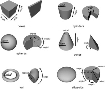
As stated in Section 2, the approach described in this paper is based on a set grammar formulation of spatial grammars. The vocabulary consists of a set of parameterized 3-D primitives, namely, box, torus, cone, cylinder, sphere, and ellipsoid. Defining more than one primitive in a grammar rule, as well as variations of the defined parameters, allows for the description of a wide range of fairly complex geometry. In addition, the use of parameterized primitives enables the definition of parametric rules, including parametric relations, as the parameters are explicitly defined for each object. Figure 1 shows a base version (left) and a version with alternative parameter values (right) for each primitive used, including the parameterization.
Primitives used illustrated by two different instances.

Using these primitives as a basis, the approach will be presented in this section, which is, according to Chase's definition (Chase, Reference Chase2002), subdivided in two main sections: the development and the application of a spatial grammar.
4.1. Development of grammar rules
To define rules in the form A → B (cf. Section 2.1), one needs to define the geometric object(s) in A and B as well as their spatial and possibly parametric relations. The fundamental aspects for the visual definition of spatial grammar rules are the creation and the positioning of geometric objects in 3-D space. This section presents two types of rule definitions, namely, nonparametric and parametric rules.
4.1.1. Development of nonparametric rules
The basis for the definition of geometric objects is the given set of parameterized 3-D primitives shown in Figure 1. An object is created by choosing one of these primitives and by assigning values to its parameters. As is usually the case in the design of solids in mechanical engineering CAD, the input is realized numerically so that exact values can be assigned to the parameters. The parameters describe the size as well as the location and orientation of the objects. In the process of designing a rule, the assigned values can be modified until the intended rule is achieved. The final parameter values defined remain static in the later application of the rule.
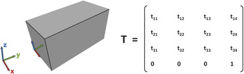
Every primitive geometric object that is created has its own local coordinate system. This coordinate system and, therefore, the attached object itself, can be translated and rotated in relation to the global coordinate system labeled x, y, z in Figure 2 (left).
Global coordinate system and object with local coordinate system (left) and general transformation matrix (right). [A color version of this figure can be viewed online at journals.cambridge.org/aie]

Through this coordinate system, the location and orientation of the object is defined or changed in 3-D space. The information about the position is kept in a transformation matrix. As is common in 3-D applications, this is a 4 × 4 matrix containing homogeneous coordinates (Fig. 2, right). It enables the calculation of different kinds of transformations in one single matrix. Several transformations can be easily concatenated by multiplying the corresponding matrices. This is especially useful for the application of spatial grammar rules, as they require the replacement of the transformed LHS of a rule, t(A), by the transformed RHS, t(B).
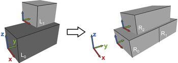
For simplicity in defining the spatial relations of objects and easy access to the transformation information, a rule is designed such that there is one reference object, L 0, in the LHS. The reference object is located in the global origin and must not be rotated. It is the basis for the detection of the spatially related objects in the rule's LHS (cf. Section 4.2.1). The transformation matrix of the reference object, T L 0, always equals the identity matrix I. Any further geometric objects in the LHS are then positioned in relation to this reference object and, therefore, in relation to the global origin. Thus, the relative spatial relations of the single objects are implicitly defined via the reference object. For an arbitrary number, m, of objects in the LHS, the transformation matrices of additionally added objects are denoted T Lj for j = 1, … , m − 1. The objects in the RHS of a rule are also positioned in relation to the global origin and, as a result, are implicitly positioned in relation to the reference object in the LHS. There is no need for a reference object in the RHS, that is, any object can be arbitrarily located and rotated. The transformation matrices of an arbitrary number, n, of objects, R i, in the RHS of a rule are denoted T Ri for i = 0, … , n − 1. Figure 3 shows an example for a rule consisting of several objects including the reference object, L 0, located at the global origin in the LHS.
Example for a nonparametric rule. [A color version of this figure can be viewed online at journals.cambridge.org/aie]

4.1.2. Development of parametric rules: Relations between parameters
In the previous section, the used parameterized primitives are assumed to be fully defined, that is, specific values are assigned to all parameters. The outcome is rules that are based on fixed, fully determined objects. Stiny (Reference Stiny1977, Reference Stiny1980a) describes parametric shape grammars where the rules are based on parameterized shapes and some or all of the parameter values are not predefined in the rule. Thus, a rule schema is defined that describes many different but related rules in one generalized rule. This allows for a wider variety of possible designs to be generated by fewer rules.
On paper, defining parametric rules is straightforward. Parametric relations and constraints are often implied using additional descriptive text (e.g., Stiny, Reference Stiny1977). However, a general computational implementation cannot be as easily created. One of the crucial points is to automatically match a general parameterized shape in the LHS of a rule to an existing design. Partially adapted from Stiny's original definition, in the following aspects for the development of parametric rules are elaborated on.
As described in the previous section, parametric rules require all the basics needed for the development of nonparametric rules. Even though the intention is to define a parametric rule, initially the geometric objects have to be fully determined, that is, specific values have to be assigned to all parameters. This is because a visual grammar system, in comparison to a grammar on paper or a hard-coded grammar, would not be able to create and display objects that initially have one or more unspecified parameters. Once the initial, nonparametric state of an object is designed, one or more of its parameters can be “unlocked,” denoted as “free parameters,” to make it parametric. Parameters that can be unlocked are not only the ones that define geometric dimensions, called “size” parameters, like width, length, radius, and so forth, but also those that determine the position of an object in 3-D space, called “location” and “orientation” parameters. Location parameters determine the translation of an object in the x, y, and z directions; orientation parameters determine the rotation defined as “yaw, pitch, and roll.”
If a parameter is unlocked, by default it is completely unrestricted, that is, any real value can be assigned to it. However, there are two ways to constrain free parameters:
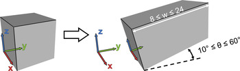
1. The values that are allowed to be assigned to a free parameter can be restricted to a certain range. An example rule with restricted ranges of possible values for the width w of a box and its rotation angle θ around the x axis is shown in Figure 4.
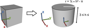
2. Parametric relations can be defined between free parameters. To make a free parameter dependent on one or more other free parameters, mathematical equations can be defined. These equations consist of different operators and mathematical functions used with either free parameters as operands and/or numeric operands. For example, in Figure 5 the radius r of the cylinder is dependent on the height using the equation r = 1/4 * h 2 − π, whereas h is restricted to a certain range.
Fig. 4.Parametric rule with free parameters that are restricted to certain ranges. [A color version of this figure can be viewed online at journals.cambridge.org/aie]
 Fig. 5.
Rule with parametric relation in the right-hand side (RHS). [A color version of this figure can be viewed online at journals.cambridge.org/aie]


This is similar to the approach taken in many commercial mechanical CAD systems for the definition of parametric relations in or between geometric models. In a CAD system, this is primarily used to lower the effort needed for the modification of a model. Changing the value of just one parameter subsequently triggers the change of one or more other parameters in the same model. The concept for grammar rules used here is basically the same; however, the main purpose is not the easier adaptation or modification of the geometry, but the definition of size or spatial relations within one or between different objects.
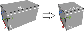
The examples given so far have considered only objects in the RHS of a rule, but the described specification of free parameters can also be used for geometric objects in the LHS. The impact of parametric objects in a rule is slightly different depending on the side of the rule in which they are defined. In the RHS a parametric object provides for the generation of a wider variety of differently sized and transformed objects (see Section 4.2.2). In the LHS a parametric object allows for matching a wider range of objects (see Section 4.2.1), so that the same rule can be applied in more cases. Taking a completely unrestricted parameter as an example, this means that all objects of the same primitive type with any arbitrary value for this free parameter can be detected as a match for the LHS. Figure 6 shows an example in which the parameter w L 0 of the box in the LHS is defined as being completely unrestricted, whereas a parametric relation between the width w R 0 in the RHS and w L 0 is defined.
Rule with completely unrestricted parameter in the left-hand side (LHS) and parametric relation in the right-hand side (RHS). [A color version of this figure can be viewed online at journals.cambridge.org/aie]

For the special case in which all size parameters of an object in the LHS are “unlocked” and completely unrestricted, all objects of the same primitive class can be found, for example, all boxes, no matter what length, width, or height. This is the most general definition of a parametric rule's LHS.
For more restricted matching in the application of a rule, a range of allowed values can be assigned to free parameters in the LHS, as well as parametric relations, as described above, to establish dependencies between free parameters in the LHS. For example, a parametric relation between length and width of a box can be defined as l = 3 * w, so that the matching is restricted to objects with a ratio of three between these two parameters. This concept can be further used for detecting scaled versions of an object. For example, if the length of a box is completely unrestricted but its width and height are restricted by the parametric relations width = length and height = length, the matching will detect all cubes, no matter which size.
For the definition of parametric relations it is for now assumed that the user sets them in the correct order, that is, in such a way that they can be evaluated correctly once the rule is applied. There is currently no mechanism for validating rules and checking for cyclic relations between free parameters, for example, width = length, length = height and height = width.
4.2. Application of spatial grammar rules
The application of grammar rules can be subdivided into different steps, which are, according to Chase (Reference Chase2002):
• the determination of a rule to apply,
• the determination of an object to which the rule is applied, and
• the determination of a matching condition.
The latter two steps concern the matching of the LHS of a rule (cf. Section 4.2.1) in the current design, which is denoted as the current working shape (CWS). Once a match is found, a further step is needed. According to the grammar formalism, the match has to be subtracted from the CWS and then be replaced by the RHS of the rule under the matching transformation and taking the evaluation of possibly defined free parameters into account (cf. Section 4.2.2).
The steps above can be performed manually, semiautomatically, or automatically. In the approach presented here, the selection of rules to apply, as well as the number of rule applications, is assumed to be done either manually by the user or randomly by the system. The remaining steps are supported automatically. The semiautomatic application of rules in this approach is restricted to the scenario of “manually selecting a rule and automatically detecting all objects to which it can be applied.” The alternative scenario of “manually selecting an object and automatically finding all rules that can be applied to it” is not included here.
4.2.1. Matching: Detection of the LHS of a rule in the CWS
Once a rule is selected, according to the equation C′ = C – t(A) + t(B) (cf. formalism in Section 2.1), the first step is to detect the LHS of the rule under a certain transformation, t(A), in the CWS. Generally, the automatic matching of the LHS of a rule in a current design is a difficult problem, especially in 3-D systems. Existing 3-D grammar systems require, for example, manual matching by the user (e.g., Piazzalunga & Fitzhorn, Reference Piazzalunga and Fitzhorn1998) or they circumvent the problem due to the nature of the provided rules and the way the transformation for every single shape is calculated (e.g., Wang & Duarte, Reference Wang and Duarte2002).
The aim of the approach presented in this paper is to automatically match the LHS of a rule in the CWS. As the approach is based on basic primitives, it can benefit from the fact that for any primitive it is explicitly known which class it is derived from, that is, the “type of primitive,” for example, box and cylinder.
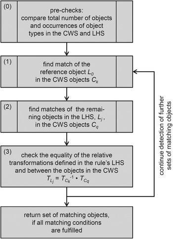
Several conditions have to be fulfilled so that a LHS with an arbitrary number of objects and defined parametric relations can be detected in a CWS. The procedure consists of four main steps, which are illustrated in Figure 7 and explained below.
General steps for matching a left-hand side (LHS) with an arbitrary number of objects in a current working shape (CWS).

Before the detailed detection is performed, a rough precheck (step 0) is useful to examine whether matching is possible, in general, illustrating an advantage of a set grammar approach. First, the geometric objects in the LHS of the rule are counted and the result is compared to the total number of objects in the CWS. If the latter is smaller than the number of objects in the LHS, a match is not possible. The second part of the precheck treats the LHS objects as isolated, single objects. It determines the primitive type of every object in the LHS and checks whether an object with the same type exists in the CWS. If there are more objects of a primitive type in the LHS than in the CWS, matching is also not possible. For example, if there are two boxes and one cylinder in the CWS but three boxes in the LHS, the rule cannot be matched. These simple prechecks can help save considerable computational time.
The approach for the detailed matching finds all possible matches of the LHS of a rule in the CWS. Beforehand, one reference object, L 0, in the LHS is identified, as it is theoretically possible that there is more than one object located in the global origin without any rotation.
Step 1. The first step is to find matches of L 0 within all the CWS objects, C k, for k = 0, … , p − 1, where p is the total number of objects in the CWS. This consists of a comparison of the objects' primitive types with the primitive type of L 0 and an equality check of the size parameters. The latter either compares the exact parameter values for a nonparametric L 0 or evaluates the free parameters in the case of a parametric L 0, which can include the check of values for parameter ranges or the mathematical evaluation of given parametric equations.
Step 2. For every match of the reference object, L 0, the remaining objects in the LHS, L j for j = 1, … , m − 1, are checked for matching in the CWS. Every L j is therefore compared to the CWS objects, C q, starting with q = 0 and incrementing q until a match is found or q = p − 1, excluding the case where C q is represented by the same object as the considered match of the reference object. The procedure is the same as in Step 1, except that L j is checked instead of L 0.
Step 3. If a certain object, L j, matches a CWS object, C q, the spatial relation between L j and L 0 has to additionally be equal to the spatial relation between C q and the considered C k. This is checked by comparing the relative transformation matrices of the two pairs of objects. The condition that has to be fulfilled is: T L j = T Ck−1 • T Cq.
If all matching conditions are fulfilled for all objects in the LHS of a rule, the set of matched objects is returned. The outcome of the complete matching procedure is the set of all matches of the LHS in the CWS, whereas every single match itself is a set of objects or at least one object.
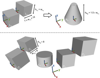
An illustrative example of the procedure is given in Figure 8. All size parameters of boxes in the LHS as well as in the CWS that are not explicitly shown are 10 mm. The upper part of the figure shows a rule with two free parameters defined in the LHS. The width of object L 1 is restricted to a range between 7 and 12 mm and the height is parametrically dependent on the width. The precheck for matching the LHS in the CWS (lower part of Fig. 8) is successful, as the number of objects, or boxes, in the LHS of the rule (two) is lower than the number of objects (five) or boxes (four) in the CWS. Object L 0 is located in the global origin without any rotation and is, therefore, the reference object of the LHS. It is checked for matches to all objects of the CWS. The first object, C 0, does not match, as it is of a different primitive type (cylinder). Object C 1, instead, is of the same type and can be further checked for matching of the parameters. No free parameters are defined for L 0, so that the parameter values must be directly compared to those of object C 1. Width, length, and height of both the objects equal 10 mm and, therefore, C 1 is the first match of the reference object L 0. Based on this, the remaining objects of the LHS, in this case only L 1, have to be checked for possible matches in the CWS. Object C 0, again, does not match because of the different primitive type. Object C 1 is the match for the reference object, L 0, and must not be checked again. Object C 2 has the same primitive type as L 1. For the detailed check, the free parameters defined for L 1 have to be taken into consideration. The width of C 2, which is 10 mm, is within the required range. The parametric relation of the height to the width, h L 1 = w L 1, is also fulfilled, as the height equals 10 mm. Further, the nonparametric length of 10 mm is also equal for both the objects. The last condition that has to be fulfilled is the equality of the relative transformation between the object pairs (L 0, L 1) and (C 1, C 2). The equation T L 1 = T C 1−1 • T C 2 is true in this case, because L 1 is translated by 5/10/10 mm in x–y–z direction (not explicitly shown in Fig. 8) in relation to L 0 and so is C 2 in relation to C 1. Therefore, the first set of matching objects is (C 1, C 2).
Example for the matching procedure: rule above, current working shape (CWS) below. [A color version of this figure can be viewed online at journals.cambridge.org/aie]

The matching procedure continues identifying the reference object's next match, L 0, in the CWS. The next object in the CWS that fulfills all conditions is C 2. Candidates for matching the second object in the LHS are the boxes C 1, C 4, and C 3, whose width and height are slightly shorter because they match the size parameters of L 1. However, taking a look at the spatial relations between the objects in all possible pairs, (C 2, C 1), (C 2, C 4), and (C 2, C 3), shows that none of the relative transformations are identical to that of (L 0, L 1) in the LHS of the rule. In the case of the pair (C 2, C 1), the absolute values in the relative transformation matrix are the same, but in comparison to the pair (C 1, C 2) the translation values in the matrix are negative and, therefore, no match is detected.
The check of the remaining objects for matching the reference object, L 0, is negative for C 3 because the values of the nonparametric width and height do not match, but positive for C 4. The objects that fulfill the conditions for matching the size parameters of L 1 are C 1, C 2, and C 3, whereas only the spatial relation of (C 4, C 3) is the same to that of (L 0, L 1). In summary, the set of all matches of the LHS in the CWS that are given in the example shown in Figure 8 consist of ([C 1, C 2], [C 4, C 3]).
4.2.2. Calculation of dimensions and transformations of the RHS objects
Following the equation C′ = C – t(A) + t(B) (cf. formalism in Section 2.1), all of the rules are realized as replacement rules, that is, the matched LHS is always fully subtracted from the CWS and replaced by the transformed RHS. Although this is not always computationally efficient, it is the most general way to create a spatial grammar interpreter.
The starting point for the replacement is the set of all possible LHS matches detected (Section 4.2.1). In a parallel grammar approach, the rule would be applied to all these matches simultaneously (Gips, Reference Gips1975). However, as is the case with most existing grammars, the approach described here is based on a serial application of rules. Therefore, a rule is always applied to only one match out of all found matches. This match can either be determined automatically by a randomized selection or manually chosen by the user.
The RHS objects that will be inserted into the CWS to replace the detected LHS objects are denoted C′i for i = 0, … , n −1, where n is the number of objects in the RHS, as introduced in Section 4.1.1. The transformation information, T Ck, of the object that was matched to the LHS reference object is explicitly available, as are the transformation matrices T Ri of the objects in the RHS of the rule (cf. Section 4.1.1). The new position of every object, C′ i, is determined in two steps: add the object to the CWS under the transformation T Ri, as defined in the RHS of the rule and, in order to fulfill the equation in the grammar formalism, apply the transformation under which the LHS was detected “t(A)” to the RHS object “t(B).” This means that the transformation of R i is additionally multiplied with the transformation of the object C k. Eventually, for all objects in the RHS, this results in the equation T C′i = T C k • T R i for i = 0, … , n − 1.
If the RHS of a rule is parametric, the free parameter values also need to be considered. First, arbitrary values, possibly within the given ranges, are assigned to all free parameters that are independent of any other parameters. This can be done either manually by the user or randomly in an automatic mode. Note that the values assigned to completely unrestricted parameters can be dependent on implicit restrictions to generate valid geometry, for example, length, width, and height have to be positive. The remaining dependent parameters are then calculated. To adapt the geometry of the objects in the RHS according to the defined parametric relations, the given equations are evaluated in the same way as during the LHS detection (cf. Section 4.2.1). The order of the equations for the evaluation is based on the order in which they are defined in the rule.
After all transformations are calculated and the parameter values are determined, the objects of the selected match can be subtracted from the CWS and replaced by the RHS objects under the calculated transformations.
Coming back to the illustrative example in Figure 8, the depicted replacement procedure is as follows: out of the set of all found matches, the match (C 1, C 2) is chosen. In this case, C 1 is identified as the match of the LHS reference object. The RHS of the rule consists of only one object, R 0. It will be the new object C′0 in the CWS after the replacement and its position is calculated according to the equation: T C′0 = T C 1 • T R 0. In addition, the parametric relation defined for R 0 is evaluated. This results in a height of 15 mm for the cone, as the width of the object C 1 that matched the object L 1 is 10 mm. Last, C 1 and C 2 are subtracted.
5. IMPLEMENTATION
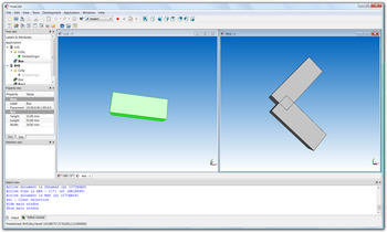
A prototype software system of the approach described in this paper has been implemented and published as open source software (http://sourceforge.net/projects/spapper/). It is based on an open source 3-D mechanical engineering CAD system (http://sourceforge.net/apps/mediawiki/free-cad/) that in turn, is built using an open source geometric modeling kernel (http://www.opencascade.org/). By using the existing user interface and the functionalities for geometry generation and manipulation provided by the kernel and the CAD system, respectively, the coding effort was kept within reasonable limits. The approach for the interpreter is realized as a Python (http://www.python.org/) module that is integrated at the startup of the system. It adds an additional workbench to the CAD system, including two special toolbars for the development and application of spatial grammars. For the development of a new rule, two windows are opened for the design of the geometric objects and their relations in the LHS and RHS (Fig. 9).
Screenshot of the prototype software system. [A color version of this figure can be viewed online at journals.cambridge.org/aie]

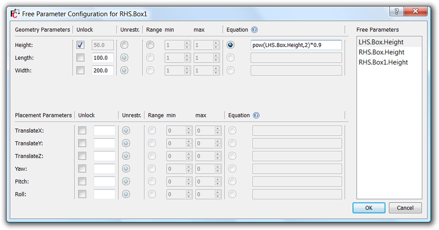
The functionality of the existing “Part”-workbench of the CAD system is used to insert and position geometric objects. Direct visual manipulation with the computer mouse is possible to translate and rotate objects. The definition of further values to, for example, set the measurements of an object, is realized using numerical inputs. The visualization of the geometry is immediately updated according to these inputs. Once fully defined, rules can be saved and later opened and edited. A rule is saved as an archive file that internally consists of an XML-file for the free parameters and two CAD files containing the geometry of the LHS and RHS as boundary representation (B-rep) data. For the definition of free parameters, a geometric object can be selected and a dialog window is opened that lists all the size, location, and orientation parameters of the object, as well as all relevant free parameters that have already been defined through other objects in a rule (Fig. 10).
Dialog window for the definition of free parameters. [A color version of this figure can be viewed online at journals.cambridge.org/aie]
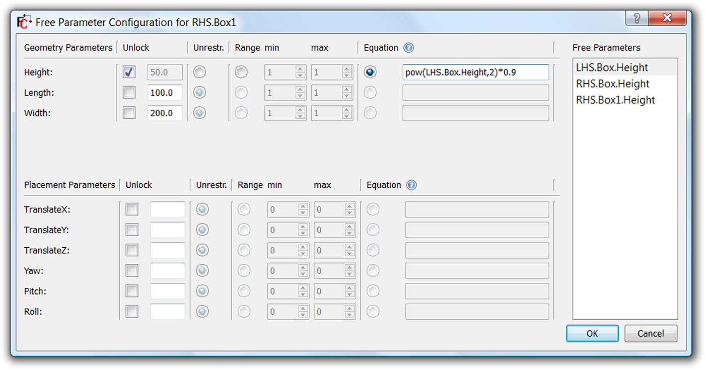
As described in Section 4.1.2, a free parameter can be completely unrestricted, restricted by a certain range, or defined by a parametric relation. In the latter case, an equation string is defined by dragging and dropping parameters from the free parameters list to the input field and extending it by typing in additional operators and operands or mathematical functions (cf. upper RHS in Fig. 10).
In addition, to ease the development of rules, the system provides the following functionality:
1. the possibility to copy objects from one rule side to the other, which is especially helpful for defining additive or subtractive rules,
2. display the LHS of a rule in the RHS window, so that it is easier to recognize and adapt the spatial relations of the objects,
3. show the local coordinate systems of selected objects to identify their orientation more easily, and
4. recalculate the position of a selected object to the global origin and relatively transform the remaining objects of the corresponding rule side.
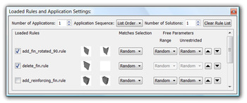
After opening a current working shape, which can be designed and saved using the standard functionality of the CAD system, saved rules can then be loaded and applied. The chosen rules are displayed in a resortable list that represents the application sequence of the rules. It is part of a dock window that further provides settings to specify the manual, semiautomatic or automatic application (Fig. 11). This includes the number of rule applications, the number of solutions to generate, the application sequence (list order or random), the selection of one of the LHS matches (random or manual) or the mode of assigning values to free parameters (random or manual). In addition, loaded rules can be activated or deactivated to explore the impact of rules on the derived solutions.
Dock window with list of loaded rules and application settings. [A color version of this figure can be viewed online at journals.cambridge.org/aie]

6. EXAMPLES
To evaluate the approach, several spatial grammars were designed using the prototype system described above.
6.1. Kindergarten grammars
The first example that was developed is based on the rules of the “kindergarten grammar.” Stiny (Reference Stiny1980b) describes rules using Froebel building blocks from the kindergarten method as an approach for the definition of design languages. For the majority of the rules the vocabulary consists of simple blocks that are orthogonally combined in many different ways. While Stiny drew the rules and created designs “by hand” on paper, Wang and Duarte (Reference Wang and Duarte2002) implemented a computational system that covers, but is not limited to, several of the kindergarten grammar rules in one rule schema, which is based on parameterized sizes and spatial relations of blocks. Deriving an instance from this schema by assigning specific values to all parameters defines a specific, nonparametric rule. This paper shows new extensions to this example through the definition of parametric rules.
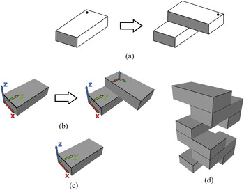
One of the very basic rules defined by Stiny adds one block on top of another turned by 90 degrees. This is described easily using the prototype system, as only the sizes and the location and orientation of the objects have to be determined. Figure 12 shows the rule as originally defined (Fig. 12a), the rule defined using the prototype system (Fig. 12b), the initial set (Fig. 12c), and the result after applying the rule seven times (Fig. 12d). In the same way that Stiny defined it in his original example, the rule is only applied to the most recently added object. The automatic LHS matching procedure always finds all existing blocks as matches because they are all the exact same size. To force the rule application to the most recently added object, the system is used in a semiautomatic mode, where, out of all the matches, the user manually selects the one match that contains the previous added object.
Basic kindergarten grammar rule as originally (a) defined by Stiny, defined in the (b) prototype system, (c) initial set, and (d) generated design. [A color version of this figure can be viewed online at journals.cambridge.org/aie]

In the original version of the rule (Fig. 12a), a label is used to realize the application only on the most recently added object. This label further determines the spatial relation between the two blocks. In this, as well as in the following examples (see below), no explicit labels are used. Instead, the local coordinate systems can be seen as implicit labels as they carry the information about the location and orientation of each object. Note that the local, as well as the global, coordinate systems are not shown in all of the resulting designs presented in this paper for better clarity.
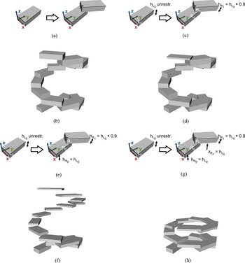
To make use of more general rotations, the rule above is edited in the prototype system so that the block on top is rotated by only 40 degrees (Fig. 13a). Using the same initial set as above, 15 applications of the new rule results in the spiral-like design shown in Figure 13b. This design could also have been generated using the 3DShaper (Wang & Duarte, Reference Wang and Duarte2002). To go beyond the capabilities of this system, the rule is further modified in a way that emphasizes the importance of the LHS matching for the rule application. The aim is to decrease the height of the block on top by 10% in comparison to the most recently added block and create a spiral with decreasing block height. Therefore, a parametric relation is defined that makes the height of block R 1 dependant on the height of L 0 using the equation h R 1 = h L 0 • 0.9. The prerequisite for this is that the parameter h L 0 is unlocked (Fig. 13c). Otherwise, the equation would always return the same result and the rule would implicitly be nonparametric. Furthermore, the rule could only be applied once to the most recently added object because the LHS matching could no longer detect the block with the decreased height.
Evolution of a “kindergarten grammar” rule including parametric relations. [A color version of this figure can be viewed online at journals.cambridge.org/aie]

The design generated using the parametric rule (Fig. 13d) is not very different from the one in Figure 13b, only the very last block is thinner than the others. The LHS matching and the evaluation of the equation are correctly performed, but the block R 0 is not considered in the parametric definition of the rule. Thus, it is inserted with its original size every time the rule is applied, replacing the previously inserted thinner block. To prevent this, an additional equation, h R 0 = h L 0, is introduced that creates a dependency between the height of R 0 with the height of L 0 and, therefore, to the object that is matched with the LHS during the application of the rule (Fig. 13e). The resulting design in Figure 13f shows that the height of the objects now correctly decreases with every step, but the single blocks are not positioned on top of each other anymore. To achieve the desired design (Fig. 13h) the translation in z direction of the second block in the RHS has to additionally be dependent on the height of L 0, achieved by the equation z R 1 = h L0 (Fig. 13g). For the development of nonparametric and, even more so, for parametric rules, it is important that the system supports the user with the possibility to easily modify already defined rules. This is especially the case because several “generate and test” cycles are often needed to reach the intended result, as seen in the example above.
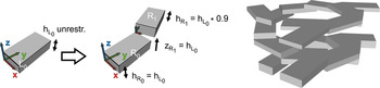
An extended version of the design generated in Figure 13h illustrating the possibility of applying a rule to more than just the most recently added object, is shown in Figure 14. After 15 applications of the rule in Figure 13g a modified version of that rule, which does not turn the second block by 40 degrees but instead by 20 degrees in the opposite direction, is applied to several blocks.
Modified rule and extended version of the design generated in Figure 13h. [A color version of this figure can be viewed online at journals.cambridge.org/aie]

6.2. Vehicle wheel rims
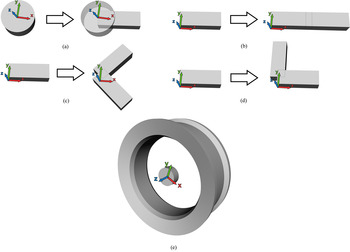
The generation of vehicle wheel rims was chosen as a mechanical engineering design example because single piece rims combine mechanical issues, for example, strength, with the need to be aesthetically pleasing. The rim rules are all nonparametric. The four rules for the generation of the spokes are shown in Figure 15. Rule (a) inserts the first spoke in relation to the hub; rule (b) adds a second spoke translated in the x direction in relation to an existing spoke; rule (c) replaces an existing spoke by two new spokes that are rotated by 45 and −45 degrees, respectively; and rule (d) adds a new spoke rotated 90 degrees in relation to an existing one.
Rules for the generation of rim spokes (a)–(d) and the initial set (e). [A color version of this figure can be viewed online at journals.cambridge.org/aie]

The rules above allow the single objects to overlap, which can help to generate more unexpected designs. In fact, interpenetration can be a valuable technique in design and designers often conceive of designs in terms of interpenetrating masses or volumes (Stiny, Reference Stiny1980b).
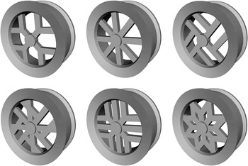
The starting design for the grammar, consisting of the felly and the hub of the rim (Fig. 15e), is designed manually in this case using the standard functionality of the underlying CAD system. To generate acceptable design solutions, the rules are applied in a semiautomatic mode where the user decides how many rules to apply and in each application step manually chooses one of the found LHS matches. A selection of different generated solutions is shown in Figure 16. While some of the results were predictable, others were unexpected, for example, the two on the right side.
Generated rim solutions.

The creation of engineering designs is always influenced by many constraints not only in the designs themselves, but also stemming from other domains like customer requirements, manufacturing, costs, and laws and standards. Production capabilities have an especially large influence on the geometry of a design. The spokes of customized rims, like the ones generated with the grammar above, are sometimes manufactured on milling machines due to the high flexibility and the low volumes produced (see, e.g., http://ead-europe.com/services.htm or http://www.speedtrix1.com/products/wheels.html). The spokes of the designs shown in Figure 16 are all in one plane. The necessity to have the spokes on one plane could be required due to restrictions of the available production capabilities. Extending these capabilities to more complex manufacturable 3-D geometry directly influences the range of valid rules that can be defined and, therefore, the resulting solutions. Generally speaking, it is possible to modify rules systematically to define new design languages that reflect changing circumstances (Stiny, Reference Stiny1980b).
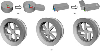
As an example, rules (a) and (d) in Figure 15 are loaded into the grammar system and edited. In the first case, the spoke is additionally rotated 10 degrees around the y axis and translated slightly in z direction (Fig. 17a). In the second case, both spokes are rotated 10 degrees around their y axes. In a subsequent step, object R 0 is set back to the global origin and, accordingly, the position of R 1 is transformed so that the RHS of the rule is in the correct spatial relation to the reference object in the LHS (Fig. 17b). Figure 17c shows three examples for rim solutions generated using the modified set of rules.
Adapted rules and newly generated rim solutions. [A color version of this figure can be viewed online at journals.cambridge.org/aie]

This example for spatial grammars was previously presented by the authors (Hoisl & Shea, Reference Hoisl and Shea2009). However, in previous work the rules were implemented directly as Python scripts, or hard coded, and restricted to 2.5-D geometry. In comparison to using the interactive, visual approach presented here, defining the rules by writing the scripts was rather tedious, as it often did not become obvious whether the intended rules were coded until their later application. This necessitated many time-consuming test and modification cycles.
6.3. Cylinder cooling fins
As a second mechanical engineering design example, the generation of cooling fins for the cylinder of, for example, motorcycle engines, is considered. In comparison to vehicle wheel rims, cooling fins do not have to be aesthetically pleasing but have to fulfill requirements concerning, primarily, the avoidance of overheating, manufacturability and fitting into the available space.
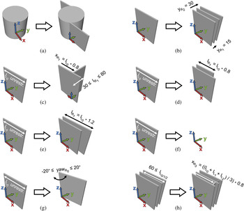
The rules were derived by analyzing the cooling fins of the cylinder of a certain type of motorcycle (see http://www.kreidlerflorett.de/Zylinder.htm) and are shown in Figure 18. Rule (a) inserts the first two fins, translated in the x and y direction in relation to the cylinder; applying rule (b), two new fins are added to an existing one at a distance of 15 mm from each other; rule (c) matches an existing fin of arbitrary length and adds another fin, which is rotated 90 degrees around the z axis, translated in x direction by 80% of the length of the matched fin and is assigned a length within the range of 30 to 80 mm; rule (d) finds an existing fin of arbitrary length and adds a new fin whose length is 80% of the length of the matched fin; rule (e) is similar to rule (d) but instead of decreasing the length of the new fin, it increases it by 20%; rule (f) matches an existing fin of arbitrary length and deletes it; rule (g) matches an existing fin of arbitrary length and rotates it around the z axis by a value within the range of −20 to 20 degrees; and rule (h) tries to find three fins that are at least 60 mm long and adds a reinforcing fin, which is realized using a cylinder primitive segment rotated 90 degrees around the y axis and translated along the x axis by 80% of the average length of the three matched fins. The last rule (h) is intended to help prevent fins from excessive vibrations if they are too long. In rules (c), (d), (e), and (g), the length of the object R 0 in the RHS is set to the same length as the object that is matched to L 0. This parametric relation is not explicitly shown in the rule figures.
Rules for the generation of cooling fins. [A color version of this figure can be viewed online at journals.cambridge.org/aie]

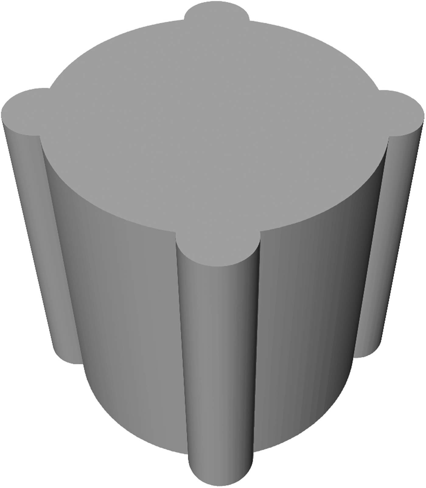
The initial set was designed manually. It consists of the cylinder, without the bore hole, and four attached smaller cylinders, which provide the material needed to fix the cylinder head with screws (Fig. 19).
Initial set for the cooling fin grammar.

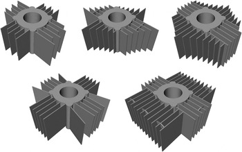
Figure 20 shows several examples of solutions generated using the rules above. The cylinder bore hole is inserted in a manual step using a Boolean operation after the application of rules is finished.
Several designs generated by applying the cooling fin grammar rules (Fig. 18).

7. DISCUSSION
For increased use and acceptance of spatial grammar systems, the development of interactive, visual grammar interpreters that are designer friendly is crucial. In an intuitive way, they allow designers to define their own rules and apply them interactively to generate different design alternatives. This is important as the design of spatial grammars is most often an iterative process where the language and full impact of the rules is often not known until they are applied. Further, integration of spatial grammars into CAD systems, including all of their functionality, is important to help encourage designers to utilize and benefit from grammatical design methods.
The approach for a spatial grammar interpreter presented in this paper comprises different aspects of the interactive, visual development, and application of 3-D spatial grammar rules. Integrated into one single system, it has several advantages over existing 3-D implementations:
1. the possibility to visually, that is, without programming, define and modify 3-D rules of
2. arbitrary rule format, which can be
3. based on a range of different solid primitives, and
4. both nonparametric and parametric;
5. an unrestricted number of rules, shapes in rules, and applications of rules;
6. automatic matching of the LHS of a rule in a CWS, including checking parametric relations; and,
7. the interactive application of rules (automatic, semiautomatic, manual) in combination with adhering to parametric relations.
Further, with regard to engineering design, this work is a step toward supporting engineers in formalizing their knowledge about design while they work in a familiar software environment, that is, a CAD tool. Although the approach is currently limited to the use of a set grammar formulation of spatial grammars that is based on geometric primitives, a wide range of designs can be rapidly generated yielding some creative and unexpected outcomes.
Several improvements to the method and implementation presented are currently under investigation.
1. As mentioned in Section 4.2.1, parametric relations have to be defined by the user in the right order so that they can be evaluated correctly during the rule application process. Thus far there is also no rule validation that can be used to avoid cyclic parameter dependencies. This can be problematic if spatial relations are redefined, for example, in the modification of a rule.
2. When defining a rule, free parameters can be defined not only for sizes but also for location and orientation parameters (cf. Section 4.1.2). However, if an LHS contains more than one object, then free location and orientation parameters cannot be defined.
3. The comparison of the relative transformation matrices can suffer from rounding errors if rotations are used in the definition or matching of objects. Currently, the rounding is statically set in the source code of the system, but it could also be considered to allow the user to manually define a tolerance.
4. After a match for the reference object is detected, the other objects in the LHS are checked for matching (cf. Section 4.1.2). If a match is found in the CWS, the remaining objects in the CWS are not checked, even if it is theoretically possible, because overlapping objects are allowed, that another object is in the exact same position and also fulfills the size requirements for matching.
5. The definition of free parameters are not directly visible in the graphical representation of a rule, but can only be seen by opening the dialog window for the free parameter definition. This should be added to the interface.
Once the issues stated above are addressed and the prototype system is more mature, it will be tested with CAD designers to evaluate its acceptance and to what extent it helps to effectively use spatial grammars in mechanical design. Several extensions to the approach to enhance the expressiveness of the definable rules and, thus, the number of potential applications, are also under investigation.
1. Enabling the use of Boolean operations in combination with parameterized primitives would allow for the definition of more complex geometry in rules. Beyond that, the expressiveness of the geometry could be enhanced using sweeping operations, which are standard in today's mechanical engineering CAD systems, to generate complex extruded or revolved objects on the basis of, for example, 2-D plane primitives. With some extensions, the same principles for rule definition and application presented in this paper can be used to include geometric objects based on Boolean or sweeping operations. This is generally feasible with regard to the prototype implementation, as the underlying modeling kernel internally represents the geometric objects using a boundary representation (B-rep). However, dealing with curved geometry (for a 2-D approach, e.g., see Jowers et al., Reference Jowers, Prats, Lim, McKay, Garner and Chase2008), for example, to define trajectories or even freeform surfaces, remains an open issue.
2. Functionality making the use of labels available needs to be added because many existing grammars include them, for example, to guide the generation process or deal with symmetries in shapes (e.g., Wang & Duarte, Reference Wang and Duarte2002). Labels can further be used to circumvent difficulties with the LHS matching, if a LHS is defined such that it consists only of a label without any further geometry.
3. Unlike the original formalism, the current approach does not consider scaling and reflection transformations for matching the LHS of a rule. The use of scaling transformations can be problematic in combination with parametric rules. This is especially the case when parametric relations between objects are defined that include mathematical operators and static values. Apart from that, parametric rules as described in this paper can also be used to detect scaled versions of an object (see Section 4.1.2). This allows the user to explicitly decide whether scaled versions should be matched or not. As there are difficulties in handling reflection transformations, especially with regard to the local coordinate systems and, therefore, the calculation of the relative transformation in cases where there are several objects in the LHS of a rule, the use of reflection transformations should be investigated in detail. In the broader context, this is related to the issue of symmetries of objects, the automatic detection of symmetry or reflection planes, as well as the question of how to deal with rotationally symmetric objects, as they can match under an infinite number of reflection or rotation transformations.
Taking a longer term perspective, more general extensions include automatic derivation of a script from the visual definition of a grammar rule using a scripting language, such as Python, to allow for the potential editing of the code by designers for enhanced rule definition and customization. Finally, as the main goal of this research is to provide a spatial grammar interpreter for mechanical engineering design problems, it is important to provide an interface to simulation in order to evaluate generated designs according to engineering requirements, for example, stresses in the vehicle wheel rims or cooling performance of the cooling fin designs. This also provides the necessary evaluation for incorporation of optimization and search methods to generate optimally directed designs using a generative grammar (see, e.g., Starling & Shea, Reference Starling and Shea2005).
8. CONCLUSION
Spatial grammars have been successfully applied in different domains to describe languages of shapes and generate alternative designs. This paper presents a new approach for a 3-D spatial grammar interpreter based on a set of parameterized primitives. It includes the interactive, visual development of 3-D spatial grammar rules as well as their automatic application. For the rule development phase, this includes the creation and positioning of geometric objects in 3-D space and the definition of nonparametric and parametric rules. For the rule application phase, automatic matching of the LHS of a rule in a current working shape is carried out along with the calculation of the positions and sizes of the objects in the RHS, in accordance with the defined parametric relations. Such flexibility to visually define spatial grammar rules, without programming or creating text files, supports both the cyclic development of a spatial grammar as well as its application to explore the design space. The approach is a step toward achieving a more general software implementation of 3-D spatial grammars within a CAD environment. Future work includes the use of Boolean and sweeping operations to create more complex geometry in rules, introduction of labels, improving the automatic rule matching and rule application method, as well as linking the system with simulation and optimization software.
ACKNOWLEDGMENTS
This research is supported by the Deutsche Forschungsgemeinschaft (DFG) through the SFB 768 “Zyklenmanagement von Innovationsprozessen.” The authors gratefully acknowledge the support of the Technische Universität München Graduate School's Thematic Graduate Center SFB 768 at Technische Universität München, Germany. We thank all authors who gave us feedback to improve the characterization of their grammar implementations (see Table 1).
Frank Hoisl is a doctoral student in the Virtual Product Development Group, Institute of Product Development, Technische Universität München, where he also graduated with a degree in mechanical engineering in 2006.
Kristina Shea has been a Professor for virtual product development at Technische Universität München since 2005. She studied mechanical engineering at Carnegie Mellon University where she completed her BS with university honors in 1993, her MS in 1995, and her PhD in 1997. Dr. Shea then worked as a Postdoctoral Researcher at EPFL in Switzerland, and in 1999 she became a University Lecturer at Cambridge University, where she led the Design Synthesis Group in the Engineering Design Center.