Introduction
In most studies, electromagnetic band gap (EBG) structures have been employed in many wireless networks and a wide variety of electromagnetic equipment due to the unique and remarkable characteristics. They exclude the surface wave's propagation in a determined frequency gap. The EBG structures are studied and recognized as the photonic band gap (PBG) structures with periodic arrangements [Reference Wang, Sun, Yang and Zhang1–Reference Hadarig, de Cos, Á lvarez and Heras4]. As is known, the artificial magnetic conductor (AMC) structures introduce a privilege like a perfect magnetic conductor (PMC) with in-phase reflection response entire certain range. Based on this, multiple low-profile antennas and mode prevention designs are applied AMCs as diverse surfaces to augment the distinguishing features [Reference Malekpoor5–Reference Barth and Iyer10]. The results presented in [Reference Nashaat, Elsadek, Abdallah, Iskander and Hennawy9] show a broadband patch array by loading diverse EBG-AMCs into the ground plane. Also, a miniaturized uni-planar metamaterial-based EBG for parallel-plate mode prevention of the switching noise in digital circuits is described in [Reference Barth and Iyer10].
The uses of AMC periodic surfaces in distinct combinations are provided to show better efficiency [Reference Rajagopal, Chennakesavan, Subburaj, Srinivasan and Varadhan7, Reference Sievenpiper, Zhang, Broas, Alex́opolous and Yablonovitch11–Reference Malekpoor and Hamidkhani17]. Among these works, a mushroom-shaped AMC structure as a beneficial approach is usually applied for diverse arrangements to achieve the low profile structures with a higher efficiency [Reference Sievenpiper, Zhang, Broas, Alex́opolous and Yablonovitch11]. In this method, used vias in periodic arrangements cannot create an easy accomplishment in the printed circuits and devices due to the drilled holes in a substrate. In the recent work, an EBG mushroom surface with a dual-layer is reported to attain a size reduction of more than 60% for multiple patch microstrip antennas [Reference Ghosh, Tran and Ngoc15]. This study is designed to present diverse two and four-element patch antennas at 2.5 GHz. It is noted that a narrow AMC bandwidth in designing broadband microwave technologies and antennas is a drastic drawback [Reference Zhu, Li, Liao and Xue18]. Therefore, there are few types of research for working on broadening the bandwidth of AMC structures [Reference Ghosh, Kumar, Sen and Das19–Reference Hadarig, de Cos and Heras22]. Based on the frequency selective surface (FSS), an AMC design for RFID applications is proposed in [Reference de Cos, Álvarez and Heras21]. In [Reference Hadarig, de Cos and Heras22], a bandwidth of 4.4% at the resonance of 6.2 GHz is demonstrated to acquire a compact AMC unit cell with relatively acceptable angular stability.
In recent years, by increasing the extension of wireless networks and satellite applications, microstrip patch antennas have attracted a great deal of attention owing to their charming specifications, like a low profile structure, light weight and simple implementation. Although a limited impedance bandwidth of the introduced antennas is accounted a notable issue in most studies. Diverse approaches in previous works have been developed to ameliorate the bandwidth of microstrip antennas [Reference Malekpoor and Hamidkhani23–Reference Malekpoor and Jam25]. Recently, by ameliorating the variety of integrated circuit technologies, the broadband AMC surfaces in the low profile antennas and microwave devices are impressively utilized with improved features [Reference Xu and Deng26–Reference Alibakhshikenari, Virdee, See, Abd-Alhameed, Ali, Falcone and Limiti36]. In [Reference Feng, Zhai, Xi, Yang, Zhang and Yang28], a low profile circular polarized antenna with the AMC surfaces like a reflector plate is reported to provide a broadband antenna with a higher gain. This antenna with AMC includes the impedance bandwidth from 1.19 to 2.37 GHz (66.3%) with the axial ratio AR bandwidth of 1.25–1.97 GHz (44.7%).
The present study reports a detailed discussion of the new broadband AMC design for applying at the suggested PSA. At first, a stacked AMC is introduced to resonate at 10.63 GHz (8–12.84 GHz) for broadband application. In the following, a low profile broadband PSA backed by the stacked AMC surface is introduced. For this purpose, two radiating tapered slots fed by CPW broaden the impedance bandwidth in X-band. Then, a broadband 11 × 17 stacked AMC reflector is developed under the antenna to obtain the ameliorated radiation efficiency. It presents the measured −10 dB impedance bandwidth in 6.97–13.34 GHz with the measured bandwidth of 62.73%. Also, the proper impedance matching and broad bandwidth with excellent compactness are achieved. Meanwhile, the performance of the AMC surface inserted in PSA is studied by introducing an equivalent waveguide feed in the position of the one half-wavelength of the radiating slot. Based on the reflection results of the equivalent waveguide feed, the optimal AMC array is determined.
Suggested printed slot antenna with broadband AMC surface
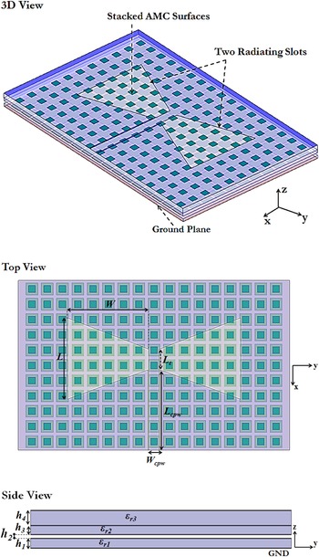
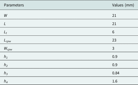
3D view and top view of suggested PSA backed by stacked AMC surface is drawn in Fig. 1. Two radiating slots with tapered slots are placed on FR4 substrate with 1.6 mm thickness. The 11 × 17 periodic patch of AMC surface is placed underneath the ground plane which is made from substrate thicknesses (FR4) of h1, h2, and h3 to couple the energy to the top layer of PSA. The dimensions of width and length of slots with tapered slots are 21 mm, and they etch on the substrate by sizes of 52 × 78 mm2. The CPW feeding system of PSA for 50-Ω input impedance is utilized. The main design parameters select as thickness h1 = h3 = 0.9 mm, h2 = 0.84 mm and h4 = 1.6 mm, εr = 4.4 and tanδ = 0.02 for FR4 substrates. A 50-Ω CPW feed is employed with the width of the strip 3 mm and the width of the slot 0.3 mm to provide the optimum impedance matching. Also, the value of Lcpw = 23 mm for CPW length is optimized. The arrangement of the 11 × 17 AMC periodic ground plane is developed below the PSA as the reactive coupling to conclude a broader bandwidth.
Structure of the suggested PSA backed by the broadband stacked AMC reflector.

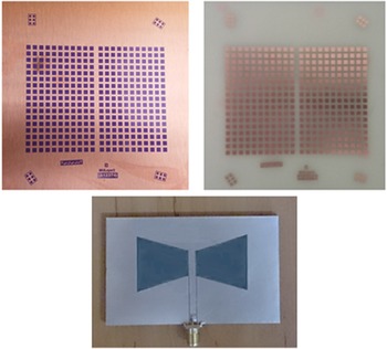
The suggested antenna excites by a 50-Ohm SMA connector from the center of the structure. The parametric studies are employed to determine the optimum dimensions and slots' length. The sizes of the suggested structure with AMC are listed in Table 1. The Images of the fabricated cases of the PSA backed by the stacked AMC reflector are shown in Fig. 2.
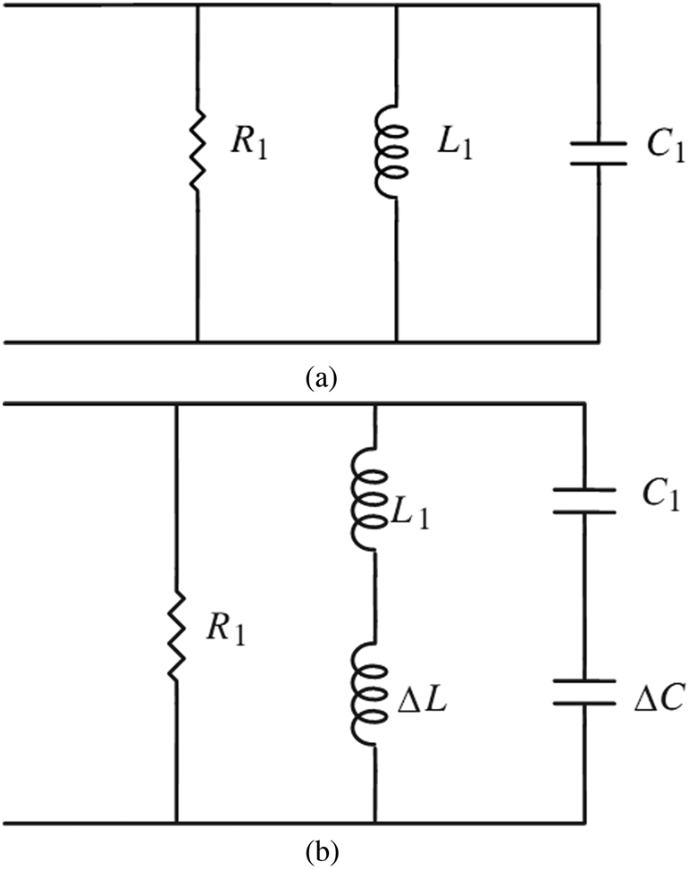
(a) Equivalent circuit for simple patch (b) Equivalent circuit for PSA with tapered slots.

Sizes of suggested PSA backed by the AMC

The proposed PSA is introduced based on tapered slots for achieving different resonances [Reference Hadarig, de Cos, Á lvarez and Heras4]. The length, width and position of slots into the tapered slot patch result in a broad bandwidth. By incorporating two slots into the patches with tapered shapes, various resonances occur and thus the impedance bandwidth can be broadened.
The conventional microstrip patch antenna is modeled as a simple resonant circuit L1C1, as seen in Fig. 2(a) with the presented lumped elements [Reference Malekpoor and Jam3]:


where y0, Le, fr, h and ɛe are the distance of feed point from the edge, the effective length of the patch, the frequency of operating band and substrate characteristics, respectively. When two slots incorporate into the patch as a taper, an additional series inductance ΔL and an additional capacitance ΔC can be modelled as shown in Fig. 2(b). Thus, different inductive and capacitive couplings in the proposed PSA design result in a wide impedance bandwidth with multiple resonances.
On the basis of the transmission line model for the rectangular radiating patch, the basic width (W) and length (L) of the patch at the resonant frequency are determined using equations (5)–(8) [Reference Malekpoor and Jam25]:


Where, εeff, h and ΔL are effective permittivity coefficient, thickness and additional length due to fringing fields, respectively. Similarly, the basic width and length of a printed microstrip dipole antenna are designed based on equations (5)–(8) for the determined operating frequency at X-band. In this case, dielectric constant substrate, εr = 4.4 is considered. The optimum sizes of the proposed PSA such as different lengths and the total height of the patch are optimized by a full-wave simulator with the parametric study.
The arrangement of the 11 × 17 AMC periodic ground plane is developed below the PDA as the reactive coupling to conclude a broader bandwidth and enhancement of radiation properties. The parametric studies are employed in the full-wave simulator to determine the optimum dimensions and arms' length.
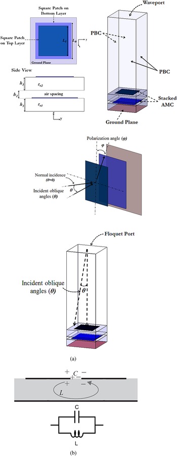
Figure 3 illustrates the structure of the suggested stacked AMC unit cell. This design is obtained by using square stacked patches with various sizes and air gap. The applied technique of the stacked patches is recognized as a known approach to enhance the bandwidth such as microstrip patch antennas [Reference Malekpoor and Hamidkhani23, Reference Malekpoor and Hamidkhani24]. By applying this approach the diverse design factors are achieved to gain an optimized broadband structure. In the suggested stacked AMC the bandwidth improvement can be tuned by the diverse components like the air gap's height, the thickness of the substrates and dimensions of two patches. The sizes of the various patches choose 3.3 and 1.9 mm and they are printed on the ground surface with the dimensions of 4.4 × 4.4 mm2. The finalized amounts of the layer's heights are considered to h1 = h3 = 0.9 mm and h2 = 0.84 mm to gain an optimum design with the FR4 substrates of εr1 = εr2 = 4.4.
Images of fabricated cases of the PSA backed by the stacked AMC reflector.

The electrical and structural specifications of the AMC are the main factors on obtaining the enhanced bandwidth. The structural specification of the broad AMC bandwidth acquires from the reactance couplings for sizes and parasitic patches. The optimum AMC bandwidth is gained by choosing the suitable electrical specification as h and εr. Based on this, the angular stability should remain without variation for broadband applications.
The mushroom-type EBG structure is formed by a via-loaded metal patch which can be characterized by an equivalent parallel LC resonator with a resonant frequency fr = 1/(2π√LC). The inductance L is obtained by the current path between the patch surface and ground plane through via. Besides, the capacitance C represents the gap effect between two adjacent patches (see Fig. 4(b)). The values of LC resonator and the frequency band gap in terms of the EBG parameters can be determined by the following formulas [Reference Sievenpiper, Zhang, Broas, Alex́opolous and Yablonovitch11]:


where, ɛ0, μ0, Webg, and g are the permittivity and permeability of free space, patch width and the gap between unit cells respectively. Also, η is the free space impedance which is 120π.
(a) Structure of suggested stacked design and simulation box by using Floquet theory (b) equivalent circuit model.

The electromagnetic properties of the suggested AMC are analyzed based on the finite element method (FEM) for periodic arrangements. As shown in Fig. 4(a), an infinite model is fulfilled with a periodic boundary condition (PBC) at the surrounding faces. For this purpose, different scan angles of incident waves (θ) are performed to recognize a wideband performance with angular stability for the reflection phase (see Fig. 4(a)) at the operating band. Moreover, the infinite model by applying the Floquet port helps to determine the operational bandwidth of AMC at a given ± 90° reflection phase.
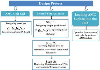
According to Fig. 5, the flow chart of the design process is introduced in the different steps. It shows the comprehensive model to attain an optimum proposed design for wideband performance.
Flow chart of the design process for the proposed structure.

Experimental and simulation results
An investigation of reflection responses of the periodic AMC is discussed in this section. Also, the printed slot antenna backed by the stacked AMC surface is tested to achieve low profile broadband antenna.
Infinite AMC unit cell with simulation results
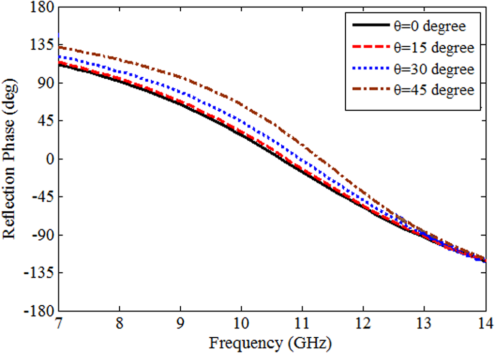
The finite element method based on the Floquet theory is utilized in Ansoft High-Frequency Structure Simulator (HFSS) to simulate the AMC designs. Figure 6 plots the reflection phase of the suggested AMC by radiating the perpendicular TE/TM waves. The frequency range for reflection phases between +90° and −90° is ordinarily considered as an AMC operation bandwidth [Reference Sievenpiper, Zhang, Broas, Alex́opolous and Yablonovitch11]:

where, fup is the frequency at which the reflection phase equals −90°, flo is the frequency at which the reflection phase equals +90°, and fc is the center frequency where the reflection phase equals 0̊.
Reflection phase of TE/TM responses of stacked AMC for indirect incident waves in φ = 0̊ and 90°.

The simulated result of 8–12.84 GHz (45.8%) for normal TE/TM waves is provided. This AMC resonates at resonances of 10.63 GHz. As compared to the known researches [Reference Sievenpiper, Zhang, Broas, Alex́opolous and Yablonovitch11, Reference Ghosh, Kumar, Sen and Das19–Reference Hadarig, de Cos and Heras22], the suggested AMC expresses the acceptable characteristics. It indicates the symmetric unit cell design with the same response for TE/TM waves, considerably broader bandwidth and tuning ability of the significant factors to gain diverse outputs for broadband application. Figure 6 plots the reflection phases of the stacked AMC for diverse inclined incident waves (θ) from 0̊ to 45̊ in two polarization angles of φ = 0̊ and 90°. A good agreement between the outcomes of TE and TM waves is identified. Thus, it can be concluded that the stacked AMC design covers X-band for wideband operation.
Measurement and simulation results of printed slot antenna loaded with AMC surface
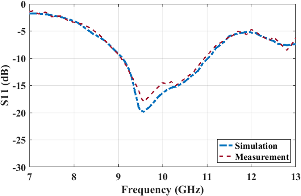
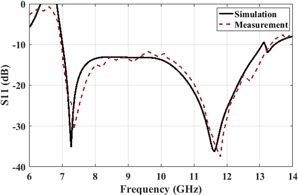
The measured and simulated S-parameters of the suggested PSA design without AMC are illustrated in Fig. 7. The PSA without AMC surface includes the measurement range of 9.05–10.95 GHz (19%) for S 11 < −10 dB. As seen from Fig. 8, the suggested antenna with the stacked AMC reflector indicates the −10 dB measured bandwidth of 62.73% in 6.97–13.34 GHz. It is concluded that the PSA with the 11 × 17 AMC reflector presents the bandwidth enhancement of almost 44% versus the PSA without the AMC reflector. On the other hand, the decrease in frequency leads to suitable miniaturization.
Measurement and simulation results of S-parameters of the suggested PSA without AMC.

Measurement and simulation results of S-parameters of the suggested PSA with stacked AMC.

The total dimensions of the PSA without AMC reflector are 1.53, 2.43 and 0.048 λL, respectively (λL is the wavelength at the lower frequency). Whereas, the total dimensions of the PSA with the stacked AMC surface are 1.163, 1.88 and 0.105 λL, respectively. It is clear that by utilizing AMC the operating frequency of the antenna reduce to the lower frequencies and consequently, a compact antenna with the reduced size is achieved. Thus, by introducing the stacked AMC reflector in the suggested PSA size reduction of 52% gains compared with the PSA without the AMC. As an interesting note, at the PSA with the AMC reflector an impedance matching of almost −40 dB occurs over the obtained bandwidth. The suggested PSA with the AMC reflector in comparison with the PSA without AMC has excellent matching.
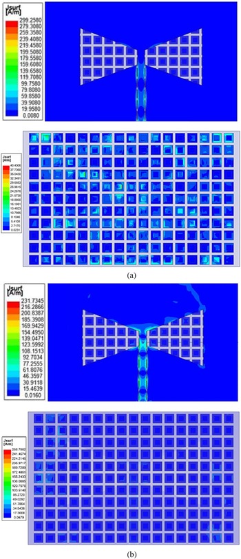
Figure 9 plots the surface current density on the patch of the printed antenna and AMC surfaces at various resonant frequencies. As seen from Fig. 9(a) at the lower resonance of 7.25 GHz of the suggested design with stacked AMC, a current distribution dominates on the CPW feed line and the sections of the AMC unit cells that are located under the CPW feed line. It is obtained that in Fig. 9(b) at the higher resonance of 11.62 GHz, the current density distributes on most unit cells of the AMC and around the tapered slots.
Surface current density on the patch of the proposed antenna with stacked AMC at: (a) 7.25 (b) 11.62 GHz.

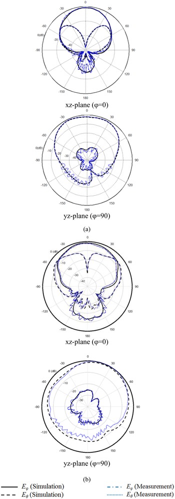
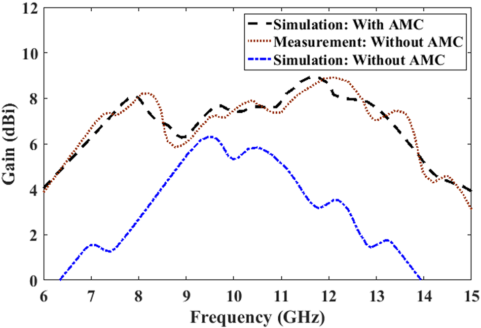
The measurement and simulation results of radiation patterns in the xz-plane and yz-plane for the suggested PSA with the stacked AMC reflector are plotted in Fig. 10. It is well found out that suitable accordance of the results is appointed. Simultaneously, the suggested design presents acceptable unidirectional radiation patterns. The maximum gain of the suggested PSA with stacked AMC surface within the operational bandwidth is 8.95 dBi, as seen in Fig. 11. Thus, the gain of the structure is impressively increased over obtained impedance bandwidth compared to the antenna without AMC.
Measurement and simulation results of radiation patterns of the suggested PSA with the stacked AMC surface for co and cross-polarization (a) 7.25 GHz (b) 11.62 GHz.

Simulated and measured gain of the suggested design with and without AMC surface.

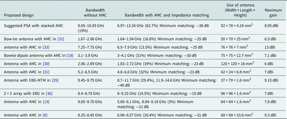
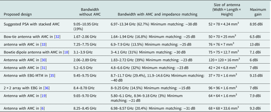
The comparative behavior of the proposed design is depicted in Table 2. It well presents the remarkable features of the suggested structure which includes considerable size reduction, wider bandwidth and enhanced maximum gain. The suggested design compared with the previous research works with planar AMCs like [Reference Liu, Li, Yang, Qi and Xu30–Reference Turpin, Wu, Werner, Martin, Bray and Lier33] introduces a broader bandwidth with more size reduction and enhanced impedance matching over the operating bandwidth.
Comparison of suggested designs with other studies
The proposed structure is considered a following design process to show an acceptable performance:
– Suggesting a wideband AMC design in 8–12.84 GHz (45.8%) for X-band operation and investigation of their properties in the infinite condition.
– Designing a broadband printed slot antenna using tapered slots fed by CPW in X-band (9.05–10.95 GHz).
– Designing a low profile printed antenna loaded with the planar AMC surface for wideband applications with improved radiation performance.
For this purpose, The suggested design compared with the previous research works with planar AMCs like [Reference Yang, Wang, Che and Wang6, Reference Zhu, Li, Liao and Xue18, Reference Ghosh, Kumar, Sen and Das19, Reference Feng, Zhai, Xi, Yang, Zhang and Yang28], and [Reference Liu, Li, Yang, Qi and Xu30–Reference Alibakhshikenari, Virdee, See, Abd-Alhameed, Ali, Falcone and Limiti36 ] introduces a broader bandwidth of more than 62% and a higher gain of 8.95 dBi with enhanced impedance matching over the operating bandwidth until −38 dB. For example, a proposed MIMO array in [Reference Zhu, Li, Liao and Xue18] with the size of 75 × 75 × 12.7 mm3 indicates a wide bandwidth of 3–4.1 GHz and a maximum gain of 7.1 dBi. Also, a reported array with EBG in [Reference Alibakhshikenari, Virdee, See, Abd-Alhameed, Ali, Falcone and Limiti36] introduces a bandwidth of 8–9.25 GHz (14.5%) with 96 × 96 × 1.6 mm3 and a high gain of 7 dBi. Thus, it can be concluded that the proposed design introduces a compact wideband antenna with enhanced gain for X-band operation.
Considerations on AMC unit cells of suggested design
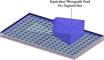
The performance of the stacked AMC surface developed in PSA is studied by applying an equivalent waveguide feed in the position of the one half-wavelength of the radiating slot element on the basis of the applied method in [Reference Malekpoor, Abolmasoumi and Hamidkhani34]. Based on the reflection results of the equivalent waveguide feeding, the optimal AMC reflector is determined. In this section, a new method of determining the patch's numbers to fulfill the AMC ground plane is introduced. It contributes to reduce the radiated power from the cavity structure within the operating band. This test setup consists of a waveguide feed including dielectric with the cavity which is organized by the slot conducting plate, the antenna substrate and AMC surface. The sizes and location of the waveguide feed are selected as a λ/2 radiating slot. The proposed method is developed in the center operating frequency of 10 GHz due to the operation of the suggested PSA without AMC in X-band. In the suggested test setup, an equivalent waveguide feed is chosen with the dimensions and location as λ/2 radiating slot which corresponds to the tapered slot, according to Fig. 12. It includes a waveguide feed in proportion to the tapered radiating slot. The waveguide port is stimulated with a dominant waveguide mode to calculate the reflection responses.
Equivalent waveguide feed setup with the dielectric-filled rectangular waveguide.

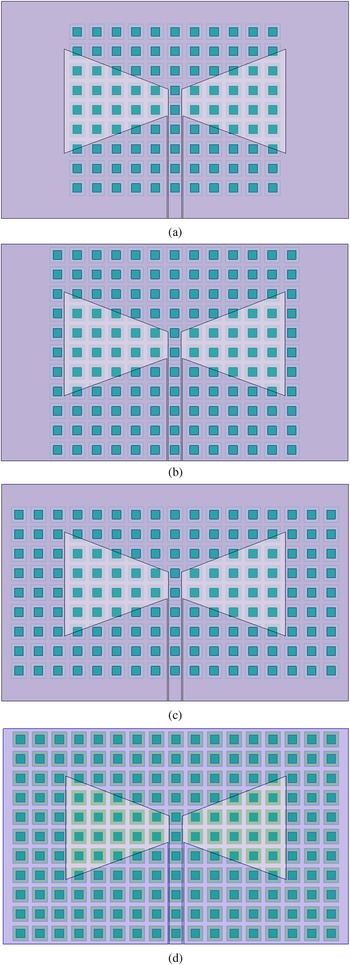
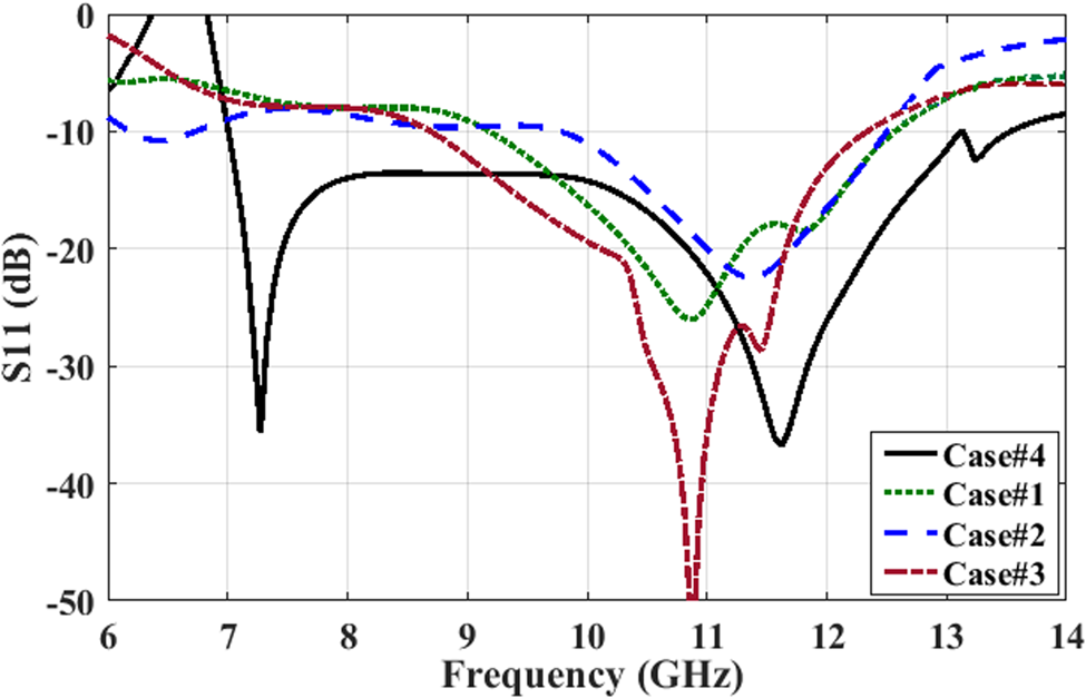
At the same time, to recognize the number of unit cells in the reflector, the reflection properties of four stacked AMC surfaces are studied. The features of four AMC surfaces are analyzed (See Fig. 13): Case#1; 9 × 11 AMC reflector, (b) Case#2; 11 × 13 AMC reflector, (c) Case#3; 9 × 17 AMC reflector and (d) Case#4; 11 × 17 AMC reflector.
Four different stacked AMC reflectors used in suggested PSA; (a) Case#1: 9 × 11 AMC surface, (b) Case#2: 11 × 13 AMC surface, (c) Case#3: 9 × 17 AMC surface and (d) Case#4: 11 × 17 AMC surface (main case).

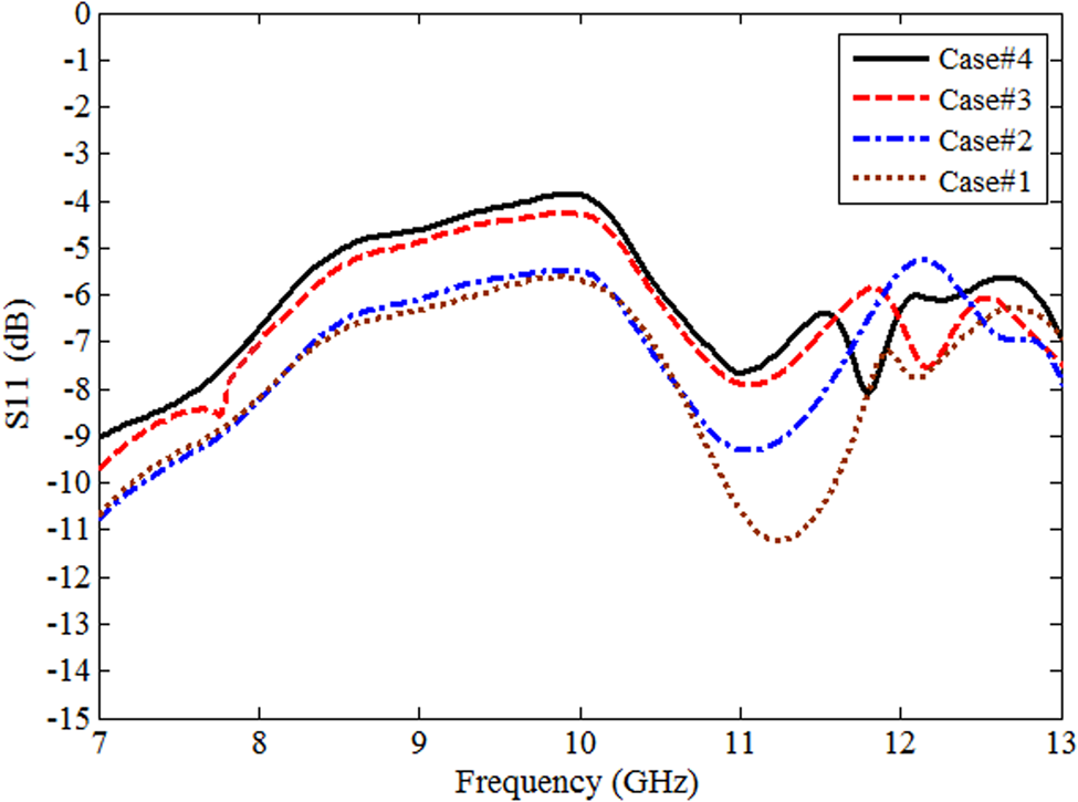
The simulated reflection coefficients S11 for the waveguide port of the equivalent waveguide feed are plotted in Fig. 14. It clearly indicates that among four suggested cases for stacked AMC array surfaces, Case#4 has the maximum reflection response around the resonance of 10 GHz. Accordingly, the reflection coefficients of the Case#4 and Case#3 are almost close to each other, whereas its difference with Cases#1 and 2 is significant. Therefore, Case#4 is chosen for optimal design to apply in the suggested printed slot antenna. It can be concluded that by increasing the number of patches used to the AMC array, the variations in reflection coefficients are slight over the operating bandwidth.
S-parameters of the suggested design by using the suggested waveguide feeding method at 10 GHz.

The simulated S-parameters of the suggested design with different stacked AMC surfaces in Fig. 11 are plotted in Fig. 15. It confirms the introduced method of the equivalent waveguide feed to recognize the optimal numbers of unit cells in the proposed structure. According to the results, the optimum Case#4 leads to wideband performance with better impedance matching.
S-parameters of the suggested design for different AMC unit cells.

Conclusion
The novel design of the stacked AMC unit cell is introduced to provide a broadband response, in this study to include 8–12.84 GHz (45.8%). The introduced AMC indicates distinguished properties with proper stability within the AMC bandwidth. It is verified that the stacked AMC is helpful in broadband applications by investigating the reflection responses at the different polarization angles for diverse incident waves. The suggested PSA with tapered slots backed by AMC reflector introduces the low profile broadband structure for X-band operation. By adding stacked AMC surface into the PSA the −10 dB impedance bandwidth of 6.97–13.34 GHz is achieved. The proper impedance matching until −40 dB, excellent compactness and broader bandwidth were obtained from the suggested PSA with AMC compared with the PSA without AMC. Besides, the uni-directional radiation patterns with a high gain are achieved. From experimental results, the acceptable efficiency is reported and it is concluded that the suggested design can be used for broadband systems. Finally, the efficiency of the AMC reflector inserted in the PSA is studied utilizing an equivalent waveguide feed in the position of the λ/2 radiating slot. In this method, to select the number of AMC patches, an equivalent waveguide feed corresponding to the center frequency is considered.
 Hossein Malekpoor was born in Iran, in 1985. He received the B.S. degree from Yazd University, Yazd, Iran in 2008, and the M.S. and Ph.D. degrees in telecommunication engineering from Shiraz University of Technology, Shiraz, Iran in 2012 and 2016 respectively.
He joined the faculty of Arak University in 2017, where he is currently an assistant professor with the Electrical Engineering Department. His research interests include microwave devices, radar systems, different antennas design, wideband microstrip antennas for UWB applications and wireless communications, analysis of antenna with equivalent circuit models, phased array antennas, periodic structures such as EBGs, AMCs and FSSs, antenna design with EBG and AMC surfaces and MIMO arrays.
 Mehdi Hamidkhani was born in Esfahan, Iran, in 1985. He received the B.E. degree in electrical engineering from the Yazd University, Iran, in 2007, and the M.Sc. degree in electrical engineering from the Iran University of Science and Technology (IUST), Tehran, Iran, in 2010, and the Ph.D. degree in electrical engineering from the Shiraz University, Shiraz, Iran, in 2016.
He is currently a professor assistant at the Islamic Azad University Dolatabad Branch, Isfahan, Iran. His current research interests are RF microwave circuits, antenna, wireless networks, IoT.