1. Introduction
Using evolving technology, modern optical mirrors are being developed with increased apertures and enhanced precision, which have high requirements in optical mirror processing robots (OMPRs) [Reference Jin, Cheng, Chen and Guo1, Reference Jiao, Shu, Chen and Zhang2]. In the optical mirror processing process, the grinding system of an OMPR is required to reach any position in the processing space with any posture. The four processing steps of the mirror surface—rough grinding, milling, fine grinding, and polishing—can be completed by the OMPR [Reference Jiang, Zhao, Wang, Zhao, Liu and Lu3, Reference Kong, Cheng, Guo, Gu and Zhang4]. Based on this, a five-degree-of-freedom (5-DOF) hybrid processing robot is designed [Reference Hosseini and Daniali5–Reference Li, Ye, Shen, Wang and Geng7]. In the OMPR process, the motion error of each motion branch and the rotation axis [Reference Gutierrez-Giles and Arteaga-Perez8, Reference Hu9] causes a contour error of the end execution point of the grinding system [Reference Ibaraki and Hiruya10]. Moreover, if the theoretical trajectory deviates from the actual track, it will lead to an uncertainty of the dwell time, and the removal amount of the optical mirror will not meet the Gaussian distribution [Reference Li, Li, Cheng, Li, Deng, Luo, Zhang, Xue and Zhang11]. Therefore, it is necessary to analyze and study the end contour error of an OMPR and improve its machining accuracy by control compensation [Reference Zhang, Li, Zhao, Zhao, Liu and Wu12, Reference Yang, Seethaler, Zhan, Lu and Zhao13].
Numerous research studies have been conducted on contour error modeling methods. To improve the estimation accuracy of contour errors, Liu et al. developed an iterative algorithm based on the osculating circle method to re-evaluate chord errors [Reference Liu, Xu, Fang and Shi14]. Izadbakhsh et al. proposed a new observer–controller structure based on function approximation techniques and Stone–Weierstrass theorem using differential equations and proved that the controller has good performance in overcoming uncertainty and reducing tracking error [Reference Izadbakhsh, Khorashadizadeh and Kheirkhahan15]. To reduce the contour error in contour-following tasks, Du et al. proposed a contour error estimation method based on a third-order osculating helix [Reference Du, Huang, Zhu and Ding16]. Yang et al. focused on developing a nearest point projection curvature circle iterative algorithm to achieve real-time estimation of multi-axis contouring errors [Reference Yang, Yang, Zhu and Yu17]. Song et al. proposed a third-order estimation algorithm for a defined joint-space contour error, using the concept of a generalized curve [Reference Song, Ma, Zhong and Yao18]. Ma et al. proposed a subregional toolpath regeneration method for contour-parallel processing based on the isoscallop method, which reduced the profile arithmetic average error and the maximum of profile deviation decrease [Reference Ma, Li, Lu, Jia, Qin and Qu19]. Considering the geometric characteristics of corner-smoothed five-axis tool paths, Hu et al. proposed an online and high-accuracy contour error estimation algorithm for five-axis computer numerical control (CNC) machining [Reference Hu, Chen and Yang20]. To obtain an accurate analytical expression of free space contour errors, Wang et al. proposed a spatial contour error estimation method based on the double Taylor expansion [Reference Wang, Hu and Zhu21]. Song et al. proposed a third-order contour error estimation algorithm to improve contour error estimation accuracy without iterative computation [Reference Song, Zhong and Ma22]. Sheng et al. proposed a comparison strategy to improve the accuracy of traditional contour error estimation [Reference Sheng and Wang23]. A novel computationally efficient contouring error estimation method for contouring control was presented by Yang et al., which eliminates the abrupt changes in contouring error vector directions that are encountered by traditional contouring error estimation methods in large-curvature regions [Reference Yang, Seethaler, Zhan, Lu and Zhao24]. To simultaneously achieve accurate contouring error estimation and high-performance contouring control for three-dimensional contouring-following tasks, Hu et al. proposed a numerical calculation-based contouring error estimation and contour compensation scheme [Reference Hu, Wang, Zhu and Zhang25].
Machine tools have their own dynamic characteristics to improve the adaptability of the control compensation. Numerous scholars have also conducted research and application for the contour error control and compensation of different machine tools. To improve the accuracy of large-curvature position tracking and contour control, Zhang et al. proposed a position compensation method composed of a cross-coupling controller and an improved position error compensator [Reference Zhang, Wu and Zou26]. Izadbakhsh et al. designed the controller of electric manipulator with Szász–Mirakyan operator as the basis function and proved that Szász–Mirakyan operator plays a good role in uncertainty compensation and improving tracking error [Reference Izadbakhsh, Khorashadizadeh and Ghandali27]. To improve the contour error control accuracy of a networked multi-axis motion system with a time-varying time delay, Wang et al. designed a linear active disturbance rejection controller for uniaxial trajectory tracking control [Reference Wang, Zhang, Dong and Yu28]. Li et al. presented the method of online self-tuning proportional–derivative controller to improve the control performance of robot contour control [Reference Li, Boonto and Nuchkrua29]. For five-axis machine tools, Chen et al. proposed a new contour error precompensation method that integrates the analytical prediction of the contour error, an optimal path-reshaping model, and a decoupling solution algorithm [Reference Chen, Sun and Xu30]. Aiming at high-precision control of CNC machine tools, Li et al. presented a contour error estimation algorithm for digital curves based on a geometrical method [Reference Li, Wang, Li and Luo31]. To solve the problems of time delay and time lag of contour error compensation by a feedback control, Wang et al. proposed a new position loop feedforward contour control method [Reference Wang, Hu and Zhu32]. Duong et al. presented an offline gain adjustment approach to reduce the contour error in five-axis high-speed machining [Reference Duong, Rodriguez-Ayerbe, Lavernhe, Tournier and Dumur33]. Cho et al. presented a novel neural network-based proportional–integral–derivative (PID) controller gain update algorithm. The proposed algorithm aimed to improve machining quality and efficiency by adjusting the PID gains in real time to minimize the contour error [Reference Cho, Song, Lee and Kim34]. In order to improve the trajectory tracking precision of a six-DOF lightweight robot, Liu et al. proposed a nonlinear proportion-deviation cross-coupling synchronization control strategy based on adjacent coupling error analysis [Reference Liu, Liang, Chu and Wu35]. Wang et al. proposed a Newton extremum-seeking algorithm-based iterative learning coordinated control strategy for contouring motion accuracy of precision multi-axial systems [Reference Wang, Hu, Zhu, He, Zhang and Mu36]. By considering the coupling effects among multiple axes, Ouyang et al. proposed a cross-coupled PID control developed in the position domain and subsequently applied the controller to a multi-axis CNC machine for contour tracking performance improvement [Reference Ouyang, Dam and Pano37].
Although there have been considerable research and application efforts on contour error modeling and contour control compensation using different methods, the contour error models are established under different working conditions, the contour error compensation control strategies are formulated under related tasks, and certain results are achieved. Moreover, most studies have focused on multi-axis CNC machine tools, and there is no in-depth study on a 5-DOF hybrid robot, which has complex dynamic characteristics. In addition, there is no relevant literature to analyze the contour error of the dwell point combined with the polishing process characteristics of the optical mirror.
In this study, the contour error and control compensation strategy of a five-DOF OMPR are studied and analyzed. The Frenet coordinate system is established based on the principle of differential geometry. Using the tangential approximation and osculating circle approximation methods, three-dimensional contour error models of the machining robot in grid trajectory, concentric circle trajectory, and spiral trajectory processing modes are derived. The control strategy of the entire machine is determined, and a parallel module feedforward combined cross-coupling control system is built. Based on the kinematic transformation relationship, the contour error control, feedforward channel gain, and compensation channel gain models are established in the parallel module task space. Subsequently, the transfer function of the cross-coupling system is deduced, and the key control variables and stability of the system are analyzed. Finally, using an experimental prototype, a contour error control compensation experiment analysis is conducted on the tool path commonly used in optical mirror processing, and the contour control strategy and related theories are verified.
2. OMPR
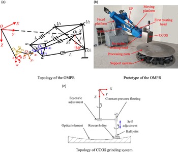
Based on the grinding process requirements, the OMPR requires at least five DOFs. The robot used in this study was a five-DOF OMPR developed using a three-DOF parallel (3UPS + UP: U - hook joint, P - moving pair, S - ball joint) manipulator combined with a two-DOF serial manipulator. The five-DOF OMPR consisted of a fixed platform, drive branch chain, constrained branch chain, moving platform, and two-DOF serial manipulator. The topological structure and prototype of the OMPR are shown in Fig. 1(a) and (b); there are three UPS drive branches and one UP constraint branch link between the movable and fixed platforms. The world coordinate system, O–XYZ, is established at the center point, O, of the mirror to be processed, the Z axis is downward, the Y axis points to the center point of the robot fixed platform, and the X axis is determined based on the right-hand rule. The fixed platform is installed at an angle of 30° with the Z axis of the world coordinate system. A fixed coordinate system, O
1–X
1
Y
1
Z
1, is established on the center, O
1, of the fixed platform, the Y
1 axis is along the
 $\overline{\overline{{O_{1}U_{1}}}}$
direction, the Z
1 axis is perpendicular to the fixed platform, and the X
1 axis is determined by the right-hand rule. A moving coordinate system, O
2–x
2
y
2
z
2, is established on the central point, O
2, of the moving platform, the y
2 axis is along the
 $\overline{\overline{{O_{2}u_{1}}}}$
direction, and the z
2 axis is perpendicular to the moving platform. Moreover, the x
2 axis is determined by the right-hand rule. The coordinate system, O
3–x
3
y
3
z
3, is established on the junction point, O
3, of the two series rotating heads. The x
3 axis is collinear with the axis of the secondary rotating head, and the y
3 axis is determined by the right-hand rule. The secondary rotating head coordinate system, O
4–x
4
y
4
z
4, is set up on tool spindle O
4 point, the z
4 axis is down the tool spindle, the y
4 axis is along the direction, and the x
4 axis is determined by the right-hand rule. The tool coordinate system, S–uvw, is established on the end tool execution point, S, and the w axis is the normal direction of the mirror to be processed. The u axis is the tangent direction of the tool path, and the v axis is determined based on the right-hand rule. The end grinding tool uses computer controlled optical surfacing (CCOS) grinding system, and its structure is shown in Fig. 1(c). The CCOS grinding system consists of a rotating motor and a revolving motor, which uses a smaller grinding head for grinding.
OMPR.

When the OMPR performs a processing task, a transformation relationship needs to be established to convert the end execution point in the world coordinate system to the fixed coordinate system.
 \begin{equation} {_{}^{O}}{\textbf{P}}{}=\textbf{q}_{1}+{_{}^{O}}{\textbf{R}}{_{O_{1}}^{}}{_{}^{O_{1}}}{\textbf{P}}{}, \end{equation}
where
O
P
is the position vector of any point in the world coordinate system,
q
1 is the position vector of the center point of the fixed platform under O–XYZ,
 ${_{}^{O_{1}}}{\textbf{P}}{}$
is the position vector of point P under O
1
–X
1
Y
1
Z
1, and
 ${_{}^{O}}{\textbf{R}}{_{O_{1}}^{}}$
is the transformation matrix from O–XYZ to O
1
–X
1
Y
1
Z
1.
(1) Inverse solution of series module
In the world coordinate system, the end point of the grinding tool on the curved surface is
 $\textbf{S}=\left[\begin{array}{l@{\quad}l@{\quad}l} x_{0} & y_{0} & z_{0} \end{array}\right]^{\mathrm{T}}$
, and a smooth trajectory curve through the point S is given as follows:
 \begin{align} \boldsymbol{\Gamma }\colon \begin{cases} x=x(t)\\[3pt] y=y(t)\\[3pt] z=z(t). \end{cases} \end{align}
Subsequently, the tangent vector,
u
, of
 $\boldsymbol{\Gamma }$
at point S and the normal vector,
w
, of the surface are
 \begin{equation} \begin{cases} \textbf{u}=\dfrac{\left[\begin{array}{l@{\quad}l@{\quad}l} \dot{x}_{0}\left(t_{0}\right) & \dot{y}_{0}(t) & \dot{z}_{0}(t) \end{array}\right]^{\mathrm{T}}}{\sqrt{\dot{x}_{0}\left(t_{0}\right)^{2}+\dot{y}_{0}(t)^{2}+\dot{z}_{0}(t)^{2}}}\\[12pt] \textbf{w}=\dfrac{\left[\begin{array}{l@{\quad}l@{\quad}l} \mathrm{\ell }_{x}\!\left(\begin{array}{l@{\quad}l@{\quad}l} x_{0} & y_{0} & z_{0} \end{array}\right) & \mathrm{\ell }_{y}\!\left(\begin{array}{l@{\quad}l@{\quad}l} x_{0} & y_{0} & z_{0} \end{array}\right) & \mathrm{\ell }_{z}\!\left(\begin{array}{l@{\quad}l@{\quad}l} x_{0} & y_{0} & z_{0} \end{array}\right) \end{array}\right]^{\mathrm{T}}}{\sqrt{\mathrm{\ell }_{x}\!\left(\begin{array}{l@{\quad}l@{\quad}l} x_{0} & y_{0} & z_{0} \end{array}\right)^{2}+\mathrm{\ell }_{y}\!\left(\begin{array}{l@{\quad}l@{\quad}l} x_{0} & y_{0} & z_{0} \end{array}\right)^{2}+\mathrm{\ell }_{z}\!\left(\begin{array}{l@{\quad}l@{\quad}l} x_{0} & y_{0} & z_{0} \end{array}\right)^{2}}}, \end{cases} \end{equation}
where
 $\mathrm{\ell }_{x}$
is the partial derivative of the surface equation to x, and t
0 is the value at a certain time.
Subsequently, the posture matrix of the end grinding tool coordinate system in the O–XYZ coordinate system is obtained as
 \begin{equation} \textbf{R}_{d}=[\begin{array}{l@{\quad}l@{\quad}l} \textbf{u} & \textbf{v} & \textbf{w} \end{array}]_{3\times 3}. \end{equation}
where
 $\textbf{v}=\textbf{u}\times \textbf{w}$
.
Thus, the vector of point O 4 in the O–XYZ coordinate system is
 \begin{equation} {_{}^{O}}{\textbf{O}}{_{4}^{}}=\textbf{S}-\textbf{R}_{d}\cdot \textbf{q}_{2} \end{equation}
where
 $\textbf{q}_{2}$
is the position vector of point S in the O
4–x
4
y
4
z
4.
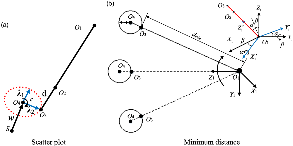
Schematic of numerical search method.

In Figure 2(a), the relative position vector of O 3 and O 2 is typically unchanged in the moving platform coordinate system, O 2–x 2 y 2 z 2. Therefore,
 \begin{equation} \textbf{r}_{2}=\textbf{r}_{3}-d_{1}\textbf{n}, \end{equation}
where
r
2 is the position vector of O
2 under O
1
–X
1
Y
1
Z
1,
r
3 is the position vector of O
3 under O
1
–X
1
Y
1
Z
1,
n
is the direction vector of
 $\overline{\overline{{O_{3}O_{1}}}}$
, and d
1 is the distance between O
2 and O
3.
Based on the structure of the two tandem rotating heads and cutter tools, the O 3 point is continuously distributed on the plane circle with the O 4 point as the center and d 2 as the radius. According to the characteristics of the vector cross-product, two vertical vectors in the plane circle are found,
 \begin{align} \begin{cases} \boldsymbol{\lambda }_{\mathrm{1}}=\dfrac{^{O}\textbf{O}_{4}\times \textbf{E}^{\mathrm{1}}}{\left| ^{O}\textbf{O}_{4}\times \textbf{E}^{\mathrm{1}}\right| }\\[12pt] \boldsymbol{\lambda }_{2}=\dfrac{\boldsymbol{\lambda }_{\mathrm{1}}\times ^{O}\textbf{O}_{4}}{\left| \boldsymbol{\lambda }_{\mathrm{1}}\times ^{O}\textbf{O}_{4}\right| }, \end{cases} \end{align}
where E 1 is a unit vector, λ 1 is the unit direction vector perpendicular to O O 4, and λ 2 is the unit direction vector perpendicular to λ 1 and O O 4.
Using the numerical search method, on the circle having O
4 as the center,
w
as the central axis, and d
2 as the radius, vectors
λ
1 and
λ
2 are searched clockwise in a certain step
 $\varsigma$
from 0 to 2 π, and a series of scattered points are obtained. The positions of the scattered points in the world coordinate system can be expressed as
 \begin{align} \begin{cases} x_{s}=^{O}O_{4x}+d_{2}\lambda _{1x}\cos \left(\varsigma \right)+d_{2}\lambda _{2x}\sin \left(\varsigma \right)\\[5pt] y_{s}=^{O}O_{4y}+d_{2}\lambda _{1y}\cos \left(\varsigma \right)+d_{2}\lambda _{2y}\sin \left(\varsigma \right)\\[5pt] z_{s}=^{O}O_{4z}+d_{2}\lambda _{1z}\cos \left(\varsigma \right)+d_{2}\lambda _{2z}\sin \left(\varsigma \right), \end{cases} \end{align}
where O O 4x , O O 4y , and O O 4z are the components of O O 4 along the coordinate axis of the world coordinate system; λ 1x , λ 1y , and λ 1z are the components of λ 1 along each coordinate axis of the world coordinate system; and λ 2x , λ 2y , and λ 2z are the components of λ 2 along each coordinate axis of the world coordinate system.
As shown in Fig. 2(b), the motion of point O 3 in the parallel module essentially adopts the fixed platform center point, O 1, as the fulcrum to swing around the X 1 and Y 1 axes. Therefore, the minimum distance to the O 1 point can be used to constrain the scattered points, and the position vector of the O 3 point in the world coordinate system O–XYZ can be obtained.
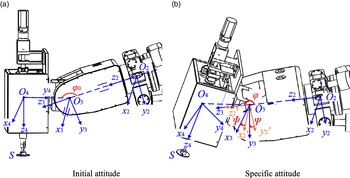
During the machining process, angles
 $\psi$
and
 $\varphi$
of the two tandem rotating heads are fine-tuned. Figure 3 shows the posture of the OMPR.
Attitude diagram of series module.

At present, the positions of points S, O 4, O 3, and O 1 in the world coordinate system are known, and the rotation angle of the first rotating head and secondary rotating head is obtained as
 \begin{equation} \varphi =\arccos \left(\frac{\overline{\overline{{O_{3}O_{4}}}}\cdot \overline{\overline{{O_{3}O_{1}}}}}{\left| \overline{\overline{{O_{3}O_{4}}}}\right| \left| \overline{\overline{{O_{3}O_{1}}}}\right| }\right). \end{equation}
 \begin{equation} \psi =\arccos \left(\textbf{x}_{3}\cdot \textbf{x}_{2}'\right) \end{equation}
where
x
3 and
 $\textbf{x}_{2}\mathit{'}$
are the unit vector expressions of the x
3 and
 $x_{2}\mathit{'}$
axes.
(2) Kinematics of parallel module
Based on Fig. 1, O 1, O 2, U i , and u i can form closed-loop vectors (i = 1, 2, 3); therefore,
 \begin{align} \begin{cases} \textbf{r}_{Ui}+l_{i}\textbf{e}_{i}=\textbf{r}_{ui}+\textbf{r}_{2}\\[5pt] \textbf{r}_{2}=L_{2}\textbf{e}_{L}, \end{cases} \end{align}
where L 2 is the length of the UP branch chain with O 2 as the end, l i and e i are the length and unit direction vector of branch chain i, e L = n is the unit direction vector of the UP branch chain under O 1 –X 1 Y 1 Z 1, r 2 is the position vector of point O 2 under O 1 –X 1 Y 1 Z 1, r Ui is the position vector of U i in O 1 –X 1 Y 1 Z 1, and r ui is the position vector of u i in O 1 —X 1 Y 1 Z 1.
The lengths of the UPS and UP chains change as follows:
 \begin{align}l_{i}=\sqrt{\left(\textbf{r}_{2}+\textbf{r}_{ui}-\textbf{r}_{Ui}\right)^{\mathrm{T}}\left(\textbf{r}_{2}+\textbf{r}_{ui}-\textbf{r}_{Ui}\right)}\end{align}
and
 \begin{equation} L_{2}={\textbf{e}_{L}}^{\mathrm{T}}\textbf{r}_{2}. \end{equation}
Furthermore, the velocity of the UP constrained branch chain and the angular velocity of the moving platform are obtained as follows:
 \begin{align} \dot{L}_{2}={\textbf{e}_{L}}^{\mathrm{T}}\dot{\textbf{r}}_{2}\quad \textrm{and}\end{align}
 \begin{equation} \boldsymbol{\omega }=\frac{\textbf{e}_{L}\times \dot{\textbf{r}}_{2}}{L_{2}}=\frac{\textbf{e}_{L\times }}{L_{2}}\dot{\textbf{r}}_{2}, \end{equation}
where
 $\textbf{e}_{L\times }=\left[\begin{array}{l@{\quad}l@{\quad}l} 0 & -e_{Lz} & e_{Ly}\\[5pt] e_{Lz} & 0 & -e_{Lx}\\[5pt] -e_{Ly} & e_{Lx} & 0 \end{array}\right]$
is the third-order antisymmetric matrix of
 $\textbf{e}_{L}$
and
 $\dot{\textbf{r}}_{2}$
is the speed of the moving platform.
The expansion acceleration of the UP branch chain and the angular acceleration of the moving platform are
 \begin{equation} \ddot{L}_{2}={\textbf{e}_{L}}^{\mathrm{T}}\ddot{\textbf{r}}_{2}+\left(\boldsymbol{\omega }\times \textbf{e}_{L}\right)^{\mathrm{T}}\dot{\textbf{r}}_{2}=\textbf{J}_{L}\ddot{\textbf{r}}_{2}+\dot{\textbf{J}}_{L}\dot{\textbf{r}}_{2}, \end{equation}
 \begin{equation} \dot{\boldsymbol{\omega }}=\frac{\textbf{e}_{L\times }}{L_{2}}\ddot{\textbf{r}}_{2}+\left[\frac{\left(\textbf{e}_{L}\times \boldsymbol{\omega }_{d}\right)_{\times }}{L_{2}}-\frac{\dot{L}_{2}}{{L_{2}}^{2}}\textbf{e}_{L\times }\right]\dot{\textbf{r}}_{2}=\textbf{J}_{d\omega }\ddot{\textbf{r}}_{2}+\dot{\textbf{J}}_{d\omega }\dot{\textbf{r}}_{2}. \end{equation}
The speed and acceleration of the UPS branch chain are
 \begin{align} \begin{cases} \dot{\textbf{L}}=\textbf{J}\dot{\textbf{r}}_{2}\\[5pt] \ddot{\textbf{L}}=\textbf{J}\ddot{\textbf{r}}_{2}+\dot{\textbf{J}}\dot{\textbf{r}} \end{cases}\!\!\!\!\!\!, \end{align}
where
 $\textbf{J}={\left[\begin{array}{l@{\quad}l@{\quad}l} \textbf{e}_{1}-\frac{{\textbf{e}_{1}}^{\mathrm{T}}\textbf{e}_{L}\textbf{r}_{u1}}{L_{2}} & \textbf{e}_{2}-\frac{{\textbf{e}_{2}}^{\mathrm{T}}\textbf{e}_{L}\textbf{r}_{u2}}{L_{2}} & \textbf{e}_{3}-\frac{{\textbf{e}_{3}}^{\mathrm{T}}\textbf{e}_{L}\textbf{r}_{u3}}{L_{2}} \end{array}\right]^{\mathrm{T}}}_{3\times 3}$
,
 $\begin{array}{l} \dot{\textbf{J}}=\left[\begin{array}{l@{\quad}l@{\quad}l} \boldsymbol{\omega }_{1}\times \textbf{e}_{1} & \boldsymbol{\omega }_{2}\times \textbf{e}_{2} & \boldsymbol{\omega }_{3}\times \textbf{e}_{3} \end{array}\right]^{\mathrm{T}}+\frac{\dot{L}_{2}}{{L_{2}}^{2}}\left[\begin{array}{l@{\quad}l@{\quad}l} {\textbf{e}_{1}}^{\mathrm{T}}\textbf{e}_{L}\textbf{r}_{u1} & {\textbf{e}_{2}}^{\mathrm{T}}\textbf{e}_{L}\textbf{r}_{u2} & {\textbf{e}_{3}}^{\mathrm{T}}\textbf{e}_{L}\textbf{r}_{u3} \end{array}\right]^{\mathrm{T}}\\[4pt] -\frac{1}{L_{2}}\left[\begin{array}{l} \left(\boldsymbol{\omega }_{1}\times \textbf{e}_{1}\right)^{\mathrm{T}}\textbf{e}_{L}{\textbf{r}_{u1}}^{\mathrm{T}}+{\textbf{e}_{1}}^{\mathrm{T}}\left(\boldsymbol{\omega }_{d}\times \textbf{e}_{L}\right){\textbf{r}_{u1}}^{\mathrm{T}}+{\textbf{e}_{1}}^{\mathrm{T}}\textbf{e}_{L}\left(\boldsymbol{\omega }_{d}\times \textbf{r}_{u1}\right)^{\mathrm{T}}\\[5pt] \left(\boldsymbol{\omega }_{2}\times \textbf{e}_{2}\right)^{\mathrm{T}}\textbf{e}_{L}{\textbf{r}_{u2}}^{\mathrm{T}}+{\textbf{e}_{2}}^{\mathrm{T}}\left(\boldsymbol{\omega }_{d}\times \textbf{e}_{L}\right){\textbf{r}_{u2}}^{\mathrm{T}}+{\textbf{e}_{2}}^{\mathrm{T}}\textbf{e}_{L}\left(\boldsymbol{\omega }_{d}\times \textbf{r}_{u2}\right)^{\mathrm{T}}\\[5pt] \left(\boldsymbol{\omega }_{3}\times \textbf{e}_{3}\right)^{\mathrm{T}}\textbf{e}_{L}{\textbf{r}_{u3}}^{\mathrm{T}}+{\textbf{e}_{3}}^{\mathrm{T}}\left(\boldsymbol{\omega }_{d}\times \textbf{e}_{L}\right){\textbf{r}_{u3}}^{\mathrm{T}}+{\textbf{e}_{3}}^{\mathrm{T}}\textbf{e}_{L}\left(\boldsymbol{\omega }_{d}\times \textbf{r}_{u3}\right)^{\mathrm{T}} \end{array}\right] \end{array}$
,
 $\dot{\textbf{L}}=\left[\begin{array}{l@{\quad}l@{\quad}l} \dot{l}_{1} & \dot{l}_{2} & \dot{l}_{3} \end{array}\right]^{\mathrm{T}}, \ddot{\textbf{L}}=\left[\begin{array}{l@{\quad}l@{\quad}l} \ddot{l}_{1} & \ddot{l}_{2} & \ddot{l}_{3} \end{array}\right]^{\mathrm{T}}$
.
The angular velocity and angular acceleration of the UPS branch chain are
 \begin{equation} \boldsymbol{\omega }_{i}=\frac{1}{l_{i}}\left[\textbf{e}_{i\times }+\left({\textbf{e}_{i}}^{\mathrm{T}}\textbf{r}_{ui}\textbf{E}-\textbf{r}_{ui}{\textbf{e}_{i}}^{\mathrm{T}}\right)\frac{\textbf{e}_{L\times }}{L_{2}}\right]\dot{\textbf{r}}_{2}=\textbf{J}_{\omega i}\dot{\textbf{r}}_{2}, \end{equation}
 \begin{equation} \dot{\boldsymbol{\omega }}_{i}=\textbf{J}_{\omega i}\ddot{\textbf{r}}_{2}+\dot{\textbf{J}}_{\omega i}\dot{\textbf{r}}_{2}, \end{equation}
where
 $\begin{array}{l} \dot{\textbf{J}}_{\omega i}=-\dfrac{\dot{l}_{i}}{{l_{i}}^{2}}\left[\textbf{e}_{i\times }+\left({\textbf{e}_{i}}^{\mathrm{T}}\textbf{r}_{ui}\textbf{E}-\textbf{r}_{ui}{\textbf{e}_{i}}^{\mathrm{T}}\right)\textbf{J}_{d\omega }\right]+\dfrac{1}{l_{i}}\left(\boldsymbol{\omega }_{i}\times \textbf{e}_{i}\right)_{\times }+\left({\textbf{e}_{i}}^{\mathrm{T}}\textbf{r}_{ui}\textbf{E}-\textbf{r}_{ui}{\textbf{e}_{i}}^{\mathrm{T}}\right)\dot{\textbf{J}}_{d\omega }\\[5pt] +[(\boldsymbol{\omega }_{i}\times \textbf{e}_{i})^{\mathrm{T}}\textbf{r}_{ui}\textbf{E}+{\textbf{e}_{i}}^{\mathrm{T}}(\boldsymbol{\omega }_{d}\times \textbf{r}_{ui})\textbf{E}-(\boldsymbol{\omega }_{d}\times \textbf{r}_{ui}){\textbf{e}_{i}}^{\mathrm{T}}-\textbf{r}_{ui}(\boldsymbol{\omega }_{i}\times \textbf{e}_{i})^{\mathrm{T}}]\textbf{J}_{d\omega }\} \end{array}$
and
E
is the third-order unit matrix.
The center of mass velocity of the UPS and UP branch chains is
 \begin{equation} \textbf{v}_{ci}=\textbf{e}_{i}\textbf{J}_{i}\dot{\textbf{r}}_{2}-\left(l_{i}-l_{bi}\right)\textbf{e}_{i\times }\textbf{J}_{\omega i}\dot{\textbf{r}}_{2}, \end{equation}
 \begin{equation} \textbf{v}_{Ly}=\textbf{e}_{L}{\textbf{e}_{L}}^{\mathrm{T}}\dot{\textbf{r}}_{2}-\left(L_{2}-L_{y}\right)\frac{1}{L_{2}}\left(\textbf{E}-\textbf{e}_{L}{\textbf{e}_{L}}^{\mathrm{T}}\right)\dot{\textbf{r}}_{2}. \end{equation}
The accelerations of the center of masses of the UPS and UP branch chains are
 \begin{equation} \begin{array}{l} \dot{\textbf{v}}_{ci}=\left\{\left(\boldsymbol{\omega }_{i}\times \textbf{e}_{i}\right)\textbf{J}_{i}+\textbf{e}_{i}\dot{\textbf{J}}_{i}+\dot{l}_{i}\textbf{e}_{i\times }\textbf{J}_{\omega i}-\left(l_{i}-l_{bi}\right)\left[\left(\boldsymbol{\omega }_{i}\times \textbf{e}_{i}\right)_{\times }\right]\textbf{J}_{\omega i}-\left(l_{i}-l_{bi}\right)\textbf{e}_{i\times }\dot{\textbf{J}}_{\omega i}\right\}\dot{\textbf{r}}_{2}\\[5pt] \;\qquad +\;\left[\textbf{e}_{i}\textbf{J}_{i}-\left(l_{i}-l_{bi}\right)\textbf{e}_{i\times }\textbf{J}_{\omega i}\right]\ddot{\textbf{r}}_{2} \end{array}, \end{equation}
 \begin{equation} \begin{array}{l} \dot{\textbf{v}}_{Ly}=\left[\left(\boldsymbol{\omega }_{d}\times \textbf{e}_{L}\right)\textbf{J}_{y}+\textbf{e}_{L}\dot{\textbf{J}}_{y}-\left(L_{2}-L_{y}\right)\dfrac{1}{L_{2}}\left(\boldsymbol{\omega }_{d}\times \textbf{e}_{L}\right)\left(\boldsymbol{\omega }_{d}\times \textbf{e}_{L}\right)^{\mathrm{T}}+\dfrac{L_{y}\dot{L}_{2}}{{L_{2}}^{2}}\left(\textbf{E}-\textbf{e}_{L}{\textbf{e}_{L}}^{\mathrm{T}}\right)\right]\dot{\textbf{r}}_{2}\\[5pt] \;\qquad +\;\left[\textbf{e}_{L}{\textbf{e}_{L}}^{\mathrm{T}}-\left(L_{2}-L_{y}\right)\dfrac{1}{L_{2}}\left(\textbf{E}-\textbf{e}_{L}{\textbf{e}_{L}}^{\mathrm{T}}\right)\right]\ddot{\textbf{r}}_{2} \end{array}, \end{equation}
where L y is the distance from the center of mass of driving chain 2 to O 2, and J y is the component of J in the y-direction.
Then, the dynamic model of the OMPR can be expressed as:
 \begin{equation} \boldsymbol{\tau }=\textbf{M}_{q}\cdot \ddot{\textbf{L}}\boldsymbol{+}\textbf{C}_{q}\cdot \dot{\textbf{L}}+\textbf{G}_{q} \end{equation}
where
 $\boldsymbol\tau$
is the control input torque,
M
q
is the inertia matrix,
 $\textbf{M}_{q}=\left(\textbf{J}^{-1}\right)^{\mathrm{T}}\textbf{M}\textbf{J}^{-1}$
,
C
q
is Coriolis force,
 $\textbf{C}_{q}=\left(\textbf{J}^{-1}\right)^{\mathrm{T}}\textbf{M}\dot{\textbf{J}}^{-1}+\left(\textbf{J}^{-1}\right)^{\mathrm{T}}\textbf{C}\textbf{J}^{-1}$
, and
G
q
is gravity,
 $\textbf{G}_{q}=\left(\textbf{J}^{-1}\right)^{\mathrm{T}}\textbf{G}$
. Due to the coupling force in the motion process of the parallel manipulator, the diagonal parts of
M
q
and
C
q
represent the force on the current joint, namely inertial force, Coriolis force, and centrifugal force, while the nondiagonal part is the force generated by one joint on other joints, that is, the coupling force. The following relationship can be obtained:
 \begin{align} \begin{cases} \textbf{M}_{qf}=\textbf{M}_{qc}\cdot \ddot{\textbf{L}}\\[5pt] \textbf{C}_{qf}=\textbf{C}_{qc}\cdot \dot{\textbf{L}}\\[5pt] \textbf{F}_{o}=\textbf{M}_{qo}\cdot \ddot{\textbf{L}}+\textbf{C}_{qo}\cdot \dot{\textbf{L}} \end{cases} \end{align}
where M qf , C qf , F o are inertia force, Coriolis force and coupling force, respectively. And,
 $\textbf{M}_{qc}=\left[\begin{array}{l@{\quad}l@{\quad}l} \textbf{M}_{q}\left(1,1\right) & & \\[5pt] & \textbf{M}_{q}\left(2,2\right) & \\[5pt] & & \textbf{M}_{q}\left(3,3\right) \end{array}\right], \textbf{M}_{qo}=\left[\begin{array}{l@{\quad}l@{\quad}l} & \textbf{M}_{q}\left(1,2\right) & \textbf{M}_{q}\left(1,3\right)\\[5pt] \textbf{M}_{q}\left(2,1\right) & & \textbf{M}_{q}\left(2,3\right)\\[5pt] \textbf{M}_{q}\left(3,1\right) & \textbf{M}_{q}\left(3,2\right) & \end{array}\right]$
,
 $\textbf{C}_{qc}=\left[\begin{array}{l@{\quad}l@{\quad}l} \textbf{C}_{q}\left(1,1\right) & & \\[5pt] & \textbf{C}_{q}\left(2,2\right) & \\[5pt] & & \textbf{C}_{q}\left(3,3\right) \end{array}\right], \textbf{C}_{qo}=\left[\begin{array}{l@{\quad}l@{\quad}l} & \textbf{C}_{q}\left(1,2\right) & \textbf{C}_{q}\left(1,3\right)\\[5pt] \textbf{C}_{q}\left(2,1\right) & & \textbf{C}_{q}\left(2,3\right)\\[5pt] \textbf{C}_{q}\left(3,1\right) & \textbf{C}_{q}\left(3,2\right) & \end{array}\right]$
.
Then, the dynamic model can be further expressed as:
 \begin{equation} \boldsymbol{\tau }=\textbf{M}_{qf}\cdot \ddot{\textbf{L}}\boldsymbol{+}\textbf{C}_{qf}\cdot \dot{\textbf{L}}+\textbf{G}_{q}+\textbf{F}_{o} \end{equation}
Since the active branch chain of the OMPR belongs to the single input single output model, it can be expressed as a linear constant continuous system:
 \begin{align} \begin{cases} \dot{x}(t)=Ax(t)+Bu\\[5pt] y=Cx(t) \end{cases} \end{align}
where
 $x(t)\in \textbf{R}^{n}, u\in \textbf{R}^{m}, A\in \textbf{R}^{n\times n}$
is a nonsingular matrix,
 $B\in \textbf{R}^{n\times m}, C\in \textbf{R}^{r\times n}$
.
3. Contour error analysis
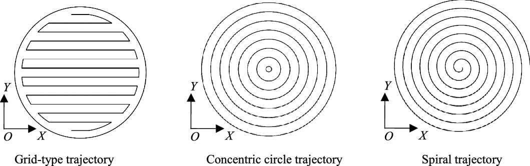
In the process of optical mirror surface processing, the grinding tool accurately traverses each removal point on the mirror surface to be processed at a certain speed. As shown in Fig. 4, the commonly used tool paths at present are the grid, concentric circle, and spiral types.
Tool paths.

For the OMPR to meet the processing requirements of different types of optical mirrors, the robot must be driven by the control system ensuring that the grinding tool can complete the above three types of contour movements.
The motion trajectory of the end grinding tool of the OMPR is composed of a series of interpolation points. The positions of these points can be described as vectors along the x, y, and z directions in the reference coordinate system, O–XYZ.
 \begin{equation} \textbf{s}(t)=\left[\begin{array}{l@{\quad}l@{\quad}l} s_{x}(t) & s_{y}(t) & s_{z}(t) \end{array}\right]^{\mathrm{T}}\!\textbf{,}\;\, t\in R, \end{equation}
where s (t) represents the trajectory parameter of the grinding tool, which is a second-order derivable continuous smooth ideal contour.
Subsequently, the unit tangent vector of the motion trajectory can be expressed as
 \begin{equation} \textbf{t}(t)=\frac{\dot{\textbf{s}}(t)}{\left| \dot{\textbf{s}}(t)\right| }, \end{equation}
where
 $\dot{\textbf{s}}(t)$
is the velocity vector.
Thus, the principal normal vector at any point of the ideal trajectory of the grinding tool is defined as follows:
 \begin{equation} \textbf{n}(t)=\frac{\rho \cdot \dot{\textbf{t}}(t)}{\left| \rho \cdot \dot{\textbf{t}}(t)\right| }, \end{equation}
where
 $\rho$
is the radius of curvature.
The tangent vector and the principal normal vector define a two-dimensional plane, which is called the osculating plane. In the three-dimensional space, there is a secondary normal vector at each point on the trajectory curve, which is perpendicular to the tangent vector and the principal normal vector. It is the second normal vector of the trajectory curve and is expressed as
 \begin{equation} \textbf{b}(t)=\textbf{t}(t)\times \textbf{n}(t). \end{equation}
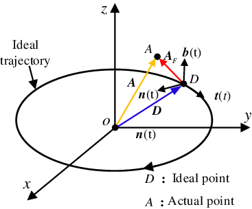
t (t), n (t), and b (t) form the Frenet coordinate system in the ideal position. As shown in Figure 5, D and A are the vectors of points D and A in O–XYZ, respectively, and the tracking error of the two points in O–XYZ is E d . A F is the position vector of point A in the Frenet coordinate system. Thus, the transformation relationship between the reference coordinate system, O–XYZ, and the Frenet coordinate system of point A is expressed as follows:
Frenet coordinate system transformation.

 \begin{equation} \begin{array}{l} T_{F}\colon \textbf{A}=\textbf{R}_{F}\textbf{A}_{F}+\boldsymbol{D}\\[5pt] T_{W}\colon \textbf{A}_{F}={\textbf{R}_{F}}^{-1}\textbf{E}_{d} \end{array}, \end{equation}
where
 $\textbf{R}_{F}=\left[\begin{array}{l@{\quad}l@{\quad}l} \textbf{t} & \textbf{n} & \textbf{b} \end{array}\right]_{3\times 3}$
is the coordinate transformation matrix, and
 ${\textbf{R}_{F}}^{-1}={\textbf{R}_{F}}^{\mathrm{T}}$
.
 $T_{F}$
represents the transformation from the Frenet coordinate system to the reference coordinate system, and
 $T_{W}$
represents the transformation from the reference coordinate system to the Frenet coordinate system.
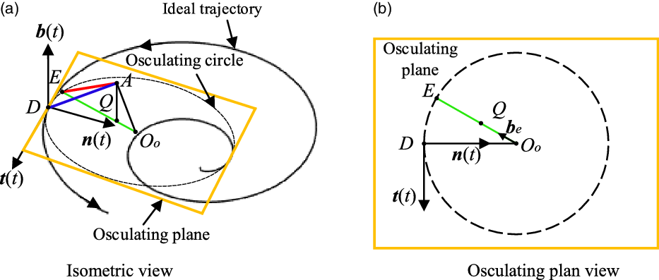
In the three-dimensional space, based on the Frenet coordinate system, the curvature and radius of curvature at a certain point can be obtained from the ideal trajectory of the grinding tool, and an osculating circle can be drawn. The contour error is solved using the shortest distance from the actual movement point of the grinding tool to the osculating circle.
The contour error of the spiral trajectory of the grinding tool in the three-dimensional space is shown in Fig. 6(a). Point Q is the projection point of point A on the osculating plane. Point E, which is closest to point A on the osculating circle, can be obtained. Thus, the contour error vector, ε , can be expressed as
Three-dimensional contour error based on osculating circle.

 \begin{equation} \boldsymbol{\varepsilon }=\left[\overline{\overline{{O_{o}A}}}\cdot \textbf{b}(t)\right]\cdot \textbf{b}(t)+\left[\rho -\left(\overline{\overline{{O_{o}A}}}\cdot \textbf{b}_{e}\right)\right]\cdot \textbf{b}_{e}, \end{equation}
where
 $\textbf{b}_{e}=\frac{\overline{\overline{{O_{o}Q}}}}{\left| \overline{\overline{{O_{o}Q}}}\right| }$
, and it is the unit orthogonal vector of
b
in the osculating plane.
The front view of a point projected onto the osculating plane is shown in Fig. 6(b), and the osculating circle is located in the osculating plane of the Frenet coordinate system. Among them, points E, Q, and O o are on the same straight line. The contour error based on the osculating circle can be obtained as
 \begin{equation} \boldsymbol{\varepsilon }=\left[\begin{array}{l} 0\\[5pt] 0\\[5pt] -E_{b} \end{array}\right]+\left(\frac{\rho }{\sqrt{{E_{t}}^{2}+\left(E_{n}-\rho \right)^{2}}}-1\right)\cdot \left[\begin{array}{l} E_{t}\\[5pt] E_{n}-\rho \\[5pt] 0 \end{array}\right]. \end{equation}
where E t , E n, and E b are the components of the actual point of the end track along each axis of the Frenet coordinate system.
4. Feedforward combined multi-axis cross-coupling contour control
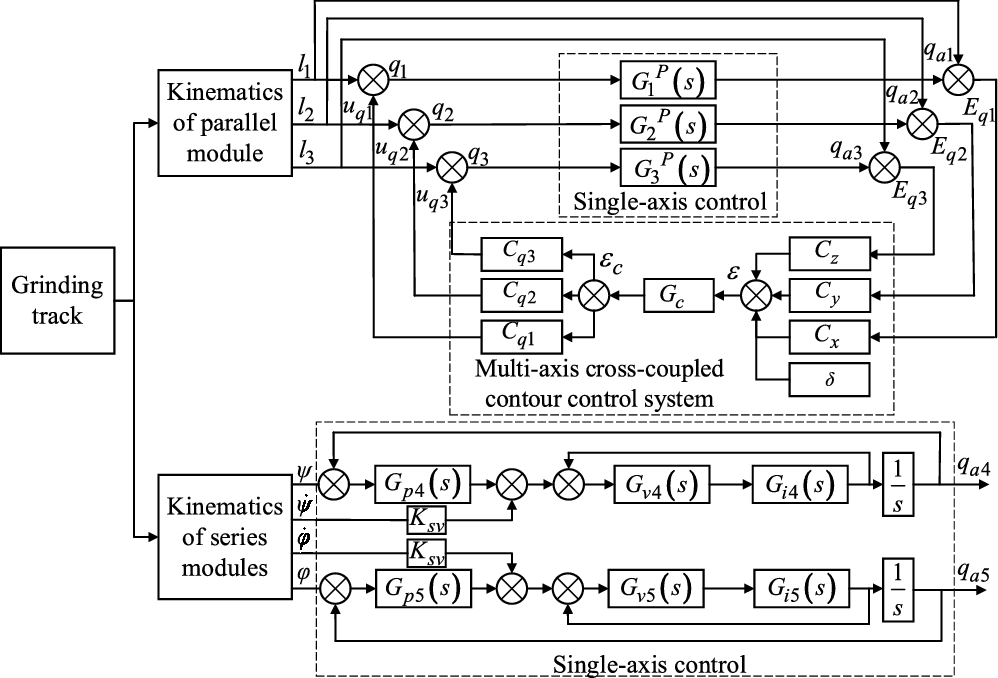
Compared to the parallel module, the series module has a lower speed, smaller range of motion, and smaller error. The series module can achieve higher motion accuracy by adopting a three-loop feedback control and speed feedforward. In this study, a cross-coupling control system is used to compensate the contour error at the end of the parallel module. Moreover, the parallel module single-joint servo control comprises speed and dynamic feedforward. The contour control strategy of the OMPR is shown in Fig. 7. Transfer functions G 1 P (s), G 2 P (s), G 3 P (s), G 4 P (s), and G 5 P (s) are used to replace the relationship between the input and the output. q a1, q a2, q a3, q a4, and q a5 are the actual output joint displacements of the control system. Tracking errors E q1, E q2, and E q3 of the parallel module single-branch chain control system are input into the contour error model, and the contour error, ε, in the task space is calculated. The contour error control quantity, ε c , is obtained using the cross-coupling controller, and a mathematical model of the compensation channel is established. The control variable, ε c , is converted into the joint space and assigned to position loop input terminals u q1, u q2, and u q3 of the three drive branch chain servo control systems to obtain actual kinematic servo system input values q 1, q 2, and q 3 after compensation. C x , C y , and C z are the forward channel gain coefficients; C q1, C q2, and C q3 are the compensation channel gain coefficients, and G c is the cross-coupling controller. G v4(s) and G v5(s) are the transfer functions of the speed loop, G i4(s) and G i5(s) are the transfer functions of the current loop, and K sv is the feedforward function of the speed loop.
Contour control strategy of OMPR.

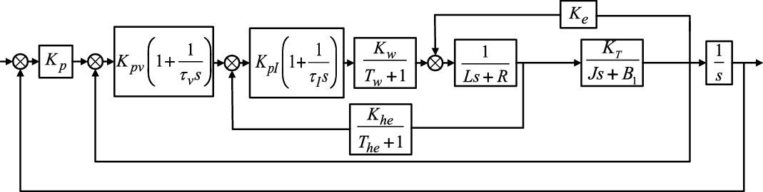
The closed-loop control of UPS branch chain includes position loop, speed loop, current loop, and servo motor. And the structure of single-branch chain servo control system is shown in Fig. 8.
Servo control system of the UPS branch chain.

In the figure, K
p
is the proportional coefficient of the position loop, K
pv
is the proportional coefficient of the speed loop,
 $\tau\!$
v
is the time constant of the velocity loop, K
pI
is the proportional coefficient of the current loop,
 $\tau\!$
I
is the current loop time constant, K
w
is the proportional coefficient of PWM inverter, T
w
is the switching frequency of PWM inverter,
 $T_{h}=0.3\sim 0.5T_{w}, K_{h}=1$
, R is the armature resistance, L is the armature inductance, K
T
is the torque coefficient, K
e
is the back EMF coefficient, J is the load moment of inertia of the motor, and B
1 is the viscous resistance.
To simplify the calculation, make:
 $K_{pv}\left(1{+}\frac{1}{\tau _{v}s}\right)=G_{1}, K_{pI}\left(1{+}\frac{1}{\tau _{I}s}\right)=G_{2}, \frac{K_{w}}{T_{w}{+}1}=G_{3}, \frac{1}{Ls{+}R}=G_{4}, \frac{K_{T}}{Js{+}B_{1}} = G_{5}, \frac{K_{he}}{T_{he}{+}1} = G_{6}$
. Then, the transfer function of UPS branch chain is
 \begin{equation} {G_{i}}^{P}\left(s\right)=\frac{G_{1}G_{2}G_{3}G_{4}G_{5}K_{p}}{\left(1\textbf{--}G_{2}G_{3}G_{4}G_{6}\right)\left(1\textbf{--}G_{4}G_{5}K_{e}\right)s\textbf{--}G_{1}G_{2}G_{3}G_{4}G_{5}s\textbf{--}G_{1}G_{2}G_{3}G_{4}G_{5}K_{p}}i=1,2,3 \end{equation}
(1) Forward channel cross-coupling gain
To establish the transfer function for system analysis, the inverse of the error Jacobian matrix, J e -1, is used to map the tracking error of the parallel module from the joint space to the task space, and the tracking error of the end moving platform of the parallel module is obtained as follows:
 \begin{equation} \textbf{E}_{d}={\left[\left(\begin{array}{l@{\quad}l@{\quad}l} \textbf{e}_{1} & \textbf{e}_{2} & \textbf{e}_{3} \end{array}\right)^{\mathrm{T}}-\frac{1}{L_{2}}\left(\begin{array}{l@{\quad}l@{\quad}l} \textbf{r}_{u1}{\textbf{e}_{1}}^{\mathrm{T}}\textbf{e}_{L} & \textbf{r}_{u2}{\textbf{e}_{2}}^{\mathrm{T}}\textbf{e}_{L} & \textbf{r}_{u3}{\textbf{e}_{3}}^{\mathrm{T}}\textbf{e}_{L} \end{array}\right)^{\mathrm{T}}\right]_{3\times 3}}^{-1}\cdot \left[\begin{array}{l} E_{q1}\\[5pt] E_{q2}\\[5pt] E_{q3} \end{array}\right]_{3\times 1}. \end{equation}
The tracking errors in any direction of X 1, Y 1, and Z 1 at the end of the parallel module are caused by the coupling of the tracking errors of the three UPS branches. So the end tracking error, F E d , of the parallel module in the Frenet coordinate system can be calculated using the single-axis tracking error of the driving branch chain as follows:
 \begin{equation} {_{}^{F}}{\textbf{E}}{_{d}^{}}={\left[\begin{array}{l@{\quad}l@{\quad}l} \textbf{t} & \textbf{n} & \textbf{b} \end{array}\right]_{3\times 3}}^{-1}\cdot {\textbf{J}_{e}}^{-1}\cdot \textbf{E}_{q}. \end{equation}
The contour error in the task space of the parallel module can be calculated utilizing F E d based on the osculating circle approximation methods.
 \begin{equation} \boldsymbol{\varepsilon }=\textbf{K}\cdot {_{}^{F}}{\boldsymbol{E }}{_{d}^{}}+\boldsymbol{\delta }, \end{equation}
where
K
is the contour error transfer matrix,
 $\textbf{K}=\left[\begin{array}{l@{\quad}l@{\quad}l} H & 0 & 0\\[5pt] 0 & H & 0\\[5pt] 0 & 0 & -1 \end{array}\right], \boldsymbol{\delta }=\left[\begin{array}{l} 0\\[5pt] -H\cdot \rho \\[5pt] 0 \end{array}\right]$
, and
 $H=\frac{\rho }{\sqrt{\left[\left({\textbf{J}_{e}}^{-1}\cdot \textbf{E}_{q}\right)^{\mathrm{T}}\textbf{t}\right]^{2}+\left[\left({\textbf{J}_{e}}^{-1}\cdot \textbf{E}_{q}\right)^{\mathrm{T}}\textbf{n}-\rho \right]^{2}}}-1$
.
Combining Fig. 7 and Eqs. (37) and (38), the forward channel gain of the cross-coupling control system is as follows:
 \begin{equation} \begin{cases} \textbf{C}_{x}=\textbf{K}\cdot {\left[\begin{array}{l@{\quad}l@{\quad}l} \textbf{t} & \textbf{n} & \textbf{b} \end{array}\right]_{3\times 3}}^{-1}\cdot {\textbf{J}_{e}}^{-1}\left(\colon \mathrm{,}1\right)\\[5pt] \textbf{C}_{y}=\textbf{K}\cdot {\left[\begin{array}{l@{\quad}l@{\quad}l} \textbf{t} & \textbf{n} & \textbf{b} \end{array}\right]_{3\times 3}}^{-1}\cdot {\textbf{J}_{e}}^{-1}\left(\colon \mathrm{,}2\right)\\[5pt] \textbf{C}_{x}=\textbf{K}\cdot {\left[\begin{array}{l@{\quad}l@{\quad}l} \textbf{t} & \textbf{n} & \textbf{b} \end{array}\right]_{3\times 3}}^{-1}\cdot {\textbf{J}_{e}}^{-1}\left(\colon \mathrm{,}3\right) \end{cases}, \end{equation}
The forward channel gain,
 $\boldsymbol\varepsilon$
, is obtained as follows:
 \begin{equation} \boldsymbol{\varepsilon }=\textbf{C}_{x}\cdot E_{q1}+\textbf{C}_{y}\cdot E_{q2}+\textbf{C}_{z}\cdot E_{q3}+\boldsymbol{\delta }. \end{equation}
(2) Compensation channel cross-coupling gain
After the contour error,
 $\boldsymbol{\varepsilon }$
, is calculated using the cross-coupling controller, the contour error compensation amount,
 $\boldsymbol{\varepsilon }_{c}$
, is obtained. It is converted into the task space of the parallel module, and the contour error,
 $\boldsymbol{\varepsilon }_{r}$
, is obtained in the fixed platform coordinate system using Eq. (33) as follows:
 \begin{equation} \boldsymbol{\varepsilon }_{r}=\left[\begin{array}{l@{\quad}l@{\quad}l} \varepsilon _{rx} & \varepsilon _{ry} & \varepsilon _{rz} \end{array}\right]^{\mathrm{T}}=\left[\begin{array}{l@{\quad}l@{\quad}l} \textbf{t} & \textbf{n} & \textbf{b} \end{array}\right]_{3\times 3}\cdot \boldsymbol{\varepsilon }_{c}, \end{equation}
Thus, the position loop compensations, u q1, u q2, and u q3, of the three driving branches in the joint space corresponding to the task space compensation are as follows:
 \begin{equation} \textbf{u}_{q}=\textbf{J}_{e}\boldsymbol{\varepsilon }_{r}, \end{equation}
where
 $\textbf{u}_{q}=\left[\begin{array}{l@{\quad}l@{\quad}l} u_{q1} & u_{q2} & u_{q3} \end{array}\right]^{\mathrm{T}}$
.
Combining Fig. 7 and Eqs. (42) and (43), the gain coefficient matrix of the compensation channel is obtained as follows:
 \begin{equation} \left\{\begin{array}{l@{\quad}l@{\quad}l} \textbf{C}_{q1}=\textbf{J}_{e}(1,\boldsymbol{:})\cdot [\textbf{t} \quad \textbf{n} \quad \textbf{b}]_{3\times 3}\\[5pt] \textbf{C}_{q2}=\textbf{J}_{e}(2,\boldsymbol{:})\cdot [\textbf{t} \quad \textbf{n} \quad \textbf{b} ]_{3\times 3}\\[5pt] \textbf{C}_{q3}=\textbf{J}_{e}(3,\textbf{:})\cdot [\textbf{t} \quad \textbf{n} \quad \textbf{b} ]_{3\times 3} \end{array}\right. ,\end{equation}
(3) Lyapunov stability analysis
According to Eq. (28), the observer of linear system can be defined as:
 \begin{align} \begin{cases} \dot{\hat{x}}=A\hat{x}+Bu+\textbf{O}_{g}\left(y-\hat{y}\right)\\[5pt] \hat{y}=C^{\mathrm{T}}\hat{x} \end{cases} \end{align}
where O g is the observation gain matrix. Then the dynamic error can be expressed as:
 \begin{equation} E=\left(A-O_{g}C^{\mathrm{T}}\right)\tilde{x} \end{equation}
where
 $\tilde{x}$
is the state estimation error matrix. From Fig. 7, the tracking error
 $\tilde{x}$
= [E
q1, E
q2, E
q3] of the single-axis UPS branch chain of the control system can be expressed as:
 \begin{equation} \begin{array}{l} E_{q1}=l_{1}\dfrac{\left(1-{G_{1}}^{P}\right)\left(1+\textbf{C}_{q1}\textbf{C}_{x}G_{c}{G_{1}}^{P}\right)}{1+C_{l}G_{c}}+l_{2}\dfrac{\left(1-{G_{2}}^{P}\right)\textbf{C}_{q1}\textbf{C}_{y}G_{c}{G_{1}}^{P}}{1+C_{l}G_{c}}\\[9pt] \;\;\qquad +\;l_{3}\dfrac{\left(1-{G_{3}}^{P}\right)\textbf{C}_{q1}\textbf{C}_{z}G_{c}{G_{1}}^{P}}{1+C_{l}G_{c}}+\dfrac{G_{c}\textbf{C}_{q1}\boldsymbol{\delta }{G_{1}}^{P}}{1+C_{l}G_{c}} \end{array} \end{equation}
 \begin{equation} \begin{array}{l} E_{q2}=l_{1}\dfrac{\left(1-{G_{1}}^{P}\right)\textbf{C}_{q2}\textbf{C}_{x}G_{c}{G_{2}}^{P}}{1+C_{l}G_{c}}+l_{2}\dfrac{\left(1-{G_{2}}^{P}\right)\left(1+\textbf{C}_{q2}\textbf{C}_{y}G_{c}{G_{2}}^{P}\right)}{1+C_{l}G_{c}}\\[9pt] \;\;\qquad+\;l_{3}\dfrac{\left(1-{G_{3}}^{P}\right)\textbf{C}_{q2}\textbf{C}_{z}G_{c}{G_{2}}^{P}}{1+C_{l}G_{c}}+\dfrac{G_{c}\textbf{C}_{q2}\boldsymbol{\delta }{G_{2}}^{P}}{1+C_{l}G_{c}} \end{array} \end{equation}
 \begin{equation} \begin{array}{l} E_{q3}=l_{1}\dfrac{\left(1-{G_{1}}^{P}\right)\textbf{C}_{q3}\textbf{C}_{x}G_{c}{G_{3}}^{P}}{1+C_{l}G_{c}}+l_{2}\dfrac{\left(1-{G_{2}}^{P}\right)\textbf{C}_{q3}\textbf{C}_{y}G_{c}{G_{3}}^{P}}{1+C_{l}G_{c}}\\[9pt] \;\;\qquad+\;l_{3}\dfrac{\left(1-{G_{3}}^{P}\right)\left(1+\textbf{C}_{q3}\textbf{C}_{z}G_{c}{G_{3}}^{P}\right)}{1+C_{l}G_{c}}+\dfrac{G_{c}\textbf{C}_{q3}\boldsymbol{\delta }{G_{3}}^{P}}{1+C_{l}G_{c}} \end{array} \end{equation}
where
 $C_{l}={G^{p}}_{1}\textbf{C}_{q1}\textbf{C}_{x}+{G^{p}}_{2}\textbf{C}_{q2}\textbf{C}_{y}+{G^{p}}_{3}\textbf{C}_{q3}\textbf{C}_{z}$
.
Similarly, from Fig. 7, the system input x = [q 1, q 2, q 3] adjusted by the multi-axis cross-coupling contour control system is deduced, and the following is obtained:
 \begin{equation} \begin{array}{l} q_{1}=l_{1}\dfrac{1+\left(\textbf{C}_{q1}\textbf{C}_{x}+\textbf{C}_{q1}\textbf{C}_{x}{G_{1}}^{P}\right)\!G_{c}}{1+C_{l}G_{c}}+l_{2}\dfrac{\textbf{C}_{q1}\textbf{C}_{y}\left(1+{G_{2}}^{P}\right)\!G_{c}}{1+C_{l}G_{c}}\\[9pt] \qquad +\;l_{3}\dfrac{\textbf{C}_{q1}\textbf{C}_{z}\left(1+{G_{3}}^{P}\right)\!G_{c}}{1+C_{l}G_{c}}+\dfrac{G_{c}\textbf{C}_{q1}\boldsymbol{\delta }}{1+C_{l}G_{c}} \end{array} \end{equation}
 \begin{equation} \begin{array}{l} q_{2}=l_{1}\dfrac{\textbf{C}_{q2}\textbf{C}_{x}\left(1+{G_{1}}^{P}\right)\!G_{c}}{1+C_{l}G_{c}}+l_{2}\dfrac{1+\left(\textbf{C}_{q2}\textbf{C}_{y}+\textbf{C}_{q2}\textbf{C}_{y}{G_{2}}^{P}\right)\!G_{c}}{1+C_{l}G_{c}}\\[9pt] \qquad +\;l_{3}\dfrac{\textbf{C}_{q2}\textbf{C}_{z}\left(1+{G_{3}}^{P}\right)\!G_{c}}{1+C_{l}G_{c}}+\dfrac{G_{c}\textbf{C}_{q2}\boldsymbol{\delta }}{1+C_{l}G_{c}} \end{array} \end{equation}
 \begin{equation} \begin{array}{l} q_{3}=l_{1}\dfrac{\textbf{C}_{q3}\textbf{C}_{x}\left(1+{G_{1}}^{P}\right)\!G_{c}}{1+C_{l}G_{c}}+l_{2}\dfrac{\textbf{C}_{q3}\textbf{C}_{y}\left(1+{G_{2}}^{P}\right)\!G_{c}}{1+C_{l}G_{c}}\\[9pt] \qquad +\;l_{3}\dfrac{1+\left(\textbf{C}_{q3}\textbf{C}_{z}+\textbf{C}_{q3}\textbf{C}_{z}{G_{3}}^{P}\right)\!G_{c}}{1+C_{l}G_{c}}+\dfrac{G_{c}\textbf{C}_{q3}\boldsymbol{\delta }}{1+C_{l}G_{c}} \end{array} \end{equation}
Based on Eqs. (50)–(52), system inputs q 1, q 2, and q 3 regulated by the cross-coupling controller are cross-coupling terms. The cross-coupling control system outputs a certain correction signal based on the contour error generated by the OMPR during the contour movement process and compensates it to the position loop input end of the single-joint control system, completing the closed-loop contour control.
Based on this, the Lyapunov closed-loop equation can be constructed as follows:
 \begin{equation} V(t)=x^{T}Px+\frac{1}{2}E^{T}P_{1}E \end{equation}
where P = P T > 0 and P
1 = P
1T > 0
 $\cdot$
The necessary and sufficient conditions for the stability of the control system are as follows: for the scalar function V with continuous first-order partial derivative, if V is positive definite and
 $\dot{V}$
is negative definite. Given Q = Q T > 0,
 $Q_{0}={Q_{0}}^{T}\gt 0$
, and
 \begin{align} \begin{cases} -Q=-PA-A^{T}P \\[5pt] -Q_{1}=\left(A-O_{g}C^{\mathrm{T}}\right)^{\mathrm{T}}P_{1}+P_{1}\left(A-O_{g}C^{\mathrm{T}}\right) \end{cases} \end{align}
Find the full derivative of V,
 \begin{equation} \dot{V}=-x^{T}Qx-E^{T}Q_{1}E. \end{equation}
Order,
 $Q_{0}=\left[\begin{array}{l@{\quad}l} Q & 0\\[5pt] 0 & \frac{1}{2}Q_{1} \end{array}\right]$
. Then,
 \begin{equation} \dot{V}=\left[\begin{array}{l@{\quad}l} x^{\mathrm{T}} & E \end{array}^{\mathrm{T}}\right]Q_{0}\left[\begin{array}{l} x\\[5pt] E \end{array}\right]\leq -\lambda _{\min }\left(Q_{0}\right)\left|\left|\left[\begin{array}{l} x\\[5pt] E \end{array}\right]\right|\right|^{2} \end{equation}
where
 $\lambda _{\min }\left(Q_{0}\right)$
is the minimum eigenvalue of matrix Q
0. Because of
 $\lambda _{\min }\left(Q_{0}\right)\gt 0$
, it can prove that
 $\dot{V}$
is negative definite, and it is proved that the closed-loop system is asymptotically stable.
(4) Simulation analysis
According to the feedforward combined multi-axis cross-coupling contour control system established, the control system is simulated and analyzed by Matlab/Simulink. Three trajectories of line, arc, and spiral in the world coordinate system are analyzed respectively. The trajectory equations are
 \begin{equation} \begin{array}{l} \text{Line}\colon \begin{cases} X=70t-R_{g}\\[5pt] Y=0\times t_{1}\\[5pt] Z=0\times t_{1}+1097 \end{cases} t_{1}=0\colon 10\\ \\ \mathrm{Arc}\colon \begin{cases} X=200\cos \left(0.2\pi t_{2}+\dfrac{3}{2}\pi \right)\\[5pt] Y=200\sin \left(0.2\pi t_{2}+\dfrac{3}{2}\pi \right)\\[5pt] Z=0\times t_{2}+1097 \end{cases} t_{2}=0\colon 10\\ \\ \text{Spiral}\colon \begin{cases} X=20t_{3}\cos \left(\dfrac{\pi }{2}t_{3}+\dfrac{\pi }{2}\right)\\[5pt] Y=20t_{3}\sin \left(\dfrac{\pi }{2}t_{3}+\dfrac{\pi }{2}\right)\\[5pt] Z=0\times t_{3}+1097 \end{cases} t_{3}=0\colon 10 \end{array} \end{equation}
As can be seen from Fig. 9(a), when only cross-coupling contour control is used for compensation, the contour error is significantly reduced. When the feedforward combined multi-axis cross-coupling contour control is used, the contour error is reduced from 0.015 to 0.004 mm, and the overall variation law of contour error is smoother. It can be seen from Fig. 9(b) that the contour error of the arc trajectory presents a regular fluctuating trend, which is caused by the error accumulation of the motion branch. When the feedforward combined multi-axis cross-coupling contour control is used, the error is reduced from the peak value of 0.193 to 0.018 mm. As can be seen from Fig. 9(c), with the increase of spiral contour, the contour error also increases, and the maximum contour error is obtained at the maximum curvature. Using feedforward combined multi-axis cross-coupling contour control, the maximum contour error can be reduced from 0.218 to 0.022 mm, and the variation trend of contour error is smoother. Therefore, the designed feedforward combined multi-axis cross-coupling contour control can effectively reduce the contour error, and the effect is better than the cross-coupling contour compensation control.
Contour error simulation.

5. Experimental analysis
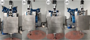
To verify the effectiveness of the established contour control model, a control system is built for the OMPR. Contour control experiments are conducted for three types of common trajectories in optical mirror processing. The experimental site and the topology of CCOS are shown in Fig. 10. The multi-axis motion controller is a programmable multi-axes controller (PMAC). On a PC, the path contour of the grinding tool in the world coordinate system is planned. Considering that the numerical search method for the inverse solution of the series module reduces the operation speed of the controller, the PC is used for the offline inverse solution of the series module. Moreover, the angle change of the two series swivel heads and the position of the parallel module moving platform are input to the PMAC to complete the control task. The displacement and velocity of five axes of the machining robot are collected, and the position and velocity of the end execution point are calculated through the forward kinematics model. Because the CCOS has pneumatic active position compensation function in the Z axis direction, only the motion parameters in the X and Y directions have research significance. During the experiment, the revolution speed of CCOS grinding system was set to 30 r/min and the rotation speed was set to 180 r/min. The linear contour, arc contour, and spiral contour are tested respectively. The trajectory equation is the same as the simulation trajectory, as shown in Eq. (57).
Experimental site.

5.1 Linear contour control compensation experiment
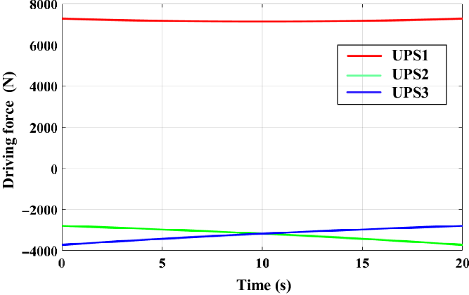
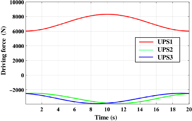
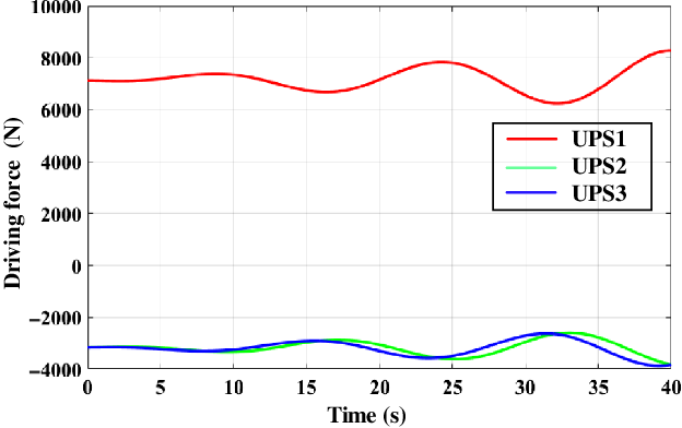
In the experiment, the trajectory of the grinding tool was a linear contour along the X axis of the world coordinate system, the length is 700 mm, the movement period was 20 s, and the sampling period was 20 ms. The experiment was conducted on an aluminum plate instead of an optical mirror. Based on the established contour error model, the contour error of the OMPR can be obtained by mapping the tracking error of each joint of the parallel module to the workspace. During the experiment, no compensation control, traditional cross-coupling compensation, and feedforward combined multi-axis cross-coupling compensation contour control experiments were conducted. The torque control mode is adopted for the linear contour experiment, and the driving force of the three driving branches in the experiment of feedforward combined multi-axis cross-coupling contour control compensation is shown in Fig. 11. Due to the inclined arrangement of the OMPR, the gravity is different in the three driving components. In order to counteract gravity, the UPS1 needs to output the force pointing to the moving platform along the branch chain, which is specified as the positive direction here. The UPS2 and UPS3 need to output the force pointing to the fixed platform along the branch chain, which is specified as the negative direction here. The UPS1 bears most of the gravity component, so the output force of the UPS1 is the largest.
Driving force output signal in linear contour linear contour.

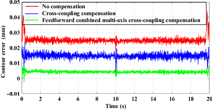
The experimental results are shown in Fig. 12. When using the traditional PID control, the contour error generated by the parallel modules is approximately 0.027 mm. When using the traditional cross-coupling compensation control strategy, the contour error is reduced to 0.018 mm. When the feedforward combined multi-axis cross-coupling control strategy is used for compensation, the contour error is further reduced to 0.006 mm. The variation trend of the experimental value and the theoretical value is the same, and the difference is only 0.002 mm, which is caused by the random error of the robot. It can be seen that the effect of the feedforward combined multi-axis cross-coupling control strategy is better than that of the traditional multi-axis cross-coupling control system.
Experiment of linear contour error control compensation.

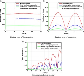
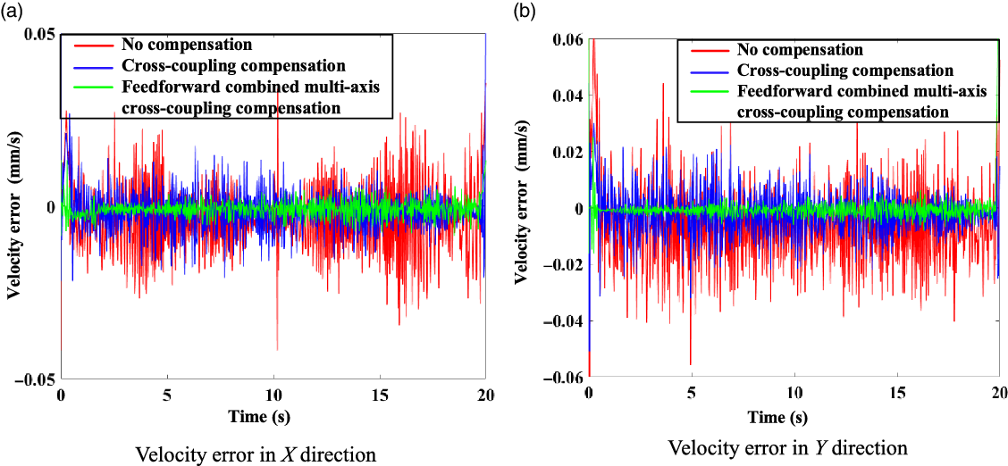
The velocity stability has a direct impact on the surface accuracy of the optical mirror. In the experiment, the velocity errors in X and Y directions in the processing of the optical mirror were tested respectively. The experimental results are shown in Fig. 13. When the compensation control mode is not adopted, the velocity errors in the X and Y directions of the linear contour are 0.025 and 0.021 mm/s. Through traditional cross-coupling compensation, the velocity errors in X and Y directions are reduced to 0.013 and 0.019 mm/s. Through feedforward combined multi-axis cross-coupling contour control, the velocity errors in X and Y directions are reduced to 0.005 and 0.006 mm/s. Therefore, the designed control compensation strategy not only reduces the velocity errors of the OMPR but also makes its motion more stable.
Linear contour velocity error.

5.2 Arc contour control compensation experiment
Taking the machined mirror as the center point, given the space arc contour trajectory of the grinding tool radius of 200 mm, the movement period is 20 s, and the sampling period is 20 ms. The experimental steps are the same as those of the linear contour control experiment. The torque control mode is adopted for the arc contour experiment, and the driving force of the three driving branches in the experiment of feedforward combined multi-axis cross-coupling contour control compensation is shown in Fig. 14. During the movement along the arc contour, the three UPS branch chains have the process of elongation and shortening. When the branch chain moves to the longest position, the heavy torque is the largest, and the driving force output value also reaches the maximum.
Driving force output signal in linear contour arc contour.

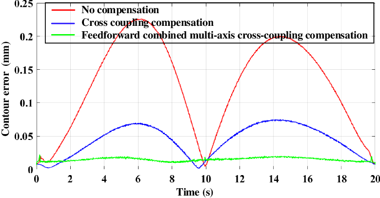
The experimental results are shown in Fig. 15. When the control compensation is not conducted, the contour error of the OMPR is approximately sinusoidal, and the error peak is 0.223 mm. When the traditional cross-coupling compensation control strategy is adopted, the contour error is reduced to 0.069 mm. When the feedforward combined multi-axis cross-coupling control strategy is used for compensation, the contour error is further reduced to approximately 0.021 mm. The variation trend of the experimental value and the theoretical value is the same, and the difference is only 0.003 mm. It is verified that the feedforward combined multi-axis cross-coupling control strategy still exhibits good compensation performance in a circular motion trajectory.
Experiment of arc contour error control compensation.

At the same time, the velocity errors in X and Y directions during processing of the optical mirror under arc contour are collected. The experimental results are shown in Fig. 16. When the compensation control mode is not adopted, the velocity errors in the X and Y directions of the arc contour are 0.055 and 0.051 mm/s. Through traditional cross-coupling compensation, the velocity errors in X and Y directions are reduced to 0.031 and 0.028 mm/s. Through feedforward combined multi-axis cross-coupling contour control, the velocity errors in X and Y directions are reduced to 0.008 and 0.010 mm/s. It can be seen that the designed control strategy also has a good effect on the velocity error compensation of arc contour.
Arc contour velocity error.

5.3 Spiral contour control compensation experiment
The given end grinding tool is a spiral contour with the starting point at the origin of the world coordinate system, the movement time is 40 s, and the sampling period is 40 ms. The experimental steps are the same as before. The torque control mode is adopted for the spiral contour experiment, and the driving force of the three driving branches in the experiment of feedforward combined multi-axis cross-coupling contour control compensation is shown in Fig. 17. When the OMPR moves along the spiral contour, the amplitude of elongation and shortening of the three UPS branches increases with the gradual increase of the curvature radius of the spiral.
Driving force output signal in linear contour spiral contour.

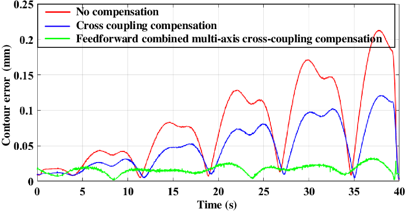
The experimental results are shown in Fig. 18. For the spiral contour, the contour error at the end of the parallel module in the control system increases as the curvature of the spiral increases. When using the traditional PID control, the maximum contour error is 0.213 mm. When the traditional cross-coupling compensation control strategy is adopted, the contour error is reduced to approximately 0.121 mm. When the feedforward combined multi-axis cross-coupling control strategy is used for compensation, the contour error is further reduced to approximately 0.030 mm. The variation trend of the experimental value and the theoretical value is the same, and the difference is only 0.008 mm. It can be seen that the feedforward combined multi-axis cross-coupling control strategy also exhibits good compensation performance in the spiral trajectory.
Experiment of spiral contour error control compensation.

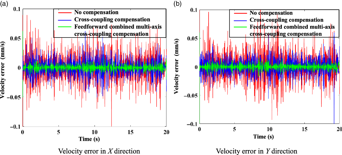
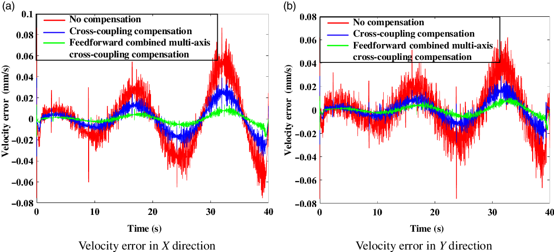
Similarly, the velocity errors of the OMPR in the X and Y directions under the spiral contour are measured. The experimental results are shown in Fig. 19. With the increase of the curvature of the spiral contour, the motion velocity errors of the machining robot in the X and Y directions also fluctuate greatly with the increase of the curvature. When the compensation control mode is not adopted, the velocity errors in the X and Y directions of the arc contour are 0.083 and 0.062 mm/s. Through traditional cross-coupling compensation, the velocity errors in X and Y directions are reduced to 0.037 and 0.025 mm/s. Through feedforward combined multi-axis cross-coupling contour control, the velocity errors in X and Y directions are reduced to 0.011 and 0.010 mm/s. It can be seen that the designed control strategy also has a good effect on the trajectory of large curvature.
Spiral contour velocity error.

6. Conclusion
This study is aimed at the problem of the contour error generated during the processing of an OMPR, which decreases the accuracy of an optical mirror surface. Considering an OMPR under specific task trajectories of the optical mirror technology, its contour error and control compensation strategy are researched and analyzed. Considering that the world coordinate system is convenient for describing the contour error of an optical mirror in the process of optical mirror machining, the robot workspace is transformed into the world coordinate system to analyze the machining trajectory. Based on the principle of differential geometry, the Frenet coordinate system is established. Using the tangential approximation and osculating circle approximation methods, three-dimensional contour error models of the OMPR in grid trajectory, concentric circle trajectory, and spiral trajectory processing modes are derived. The control strategy of the entire machine is determined, and a parallel module feedforward combined multi-axis cross-coupling control system is built. Based on the kinematic transformation relationship, the contour error control, feedforward channel gain, and compensation channel gain models are established in the parallel module task space. Subsequently, the transfer function of the cross-coupling system is obtained, and the key control variables and stability of the system are analyzed to ensure the theoretical stability of the control system. Finally, an experimental analysis is conducted on an experimental prototype, and the results show that the established feedforward combined multi-axis cross-coupling control compensation strategy can achieve a good compensation effect on the straight line, arc, and spiral machining trajectories of the optical mirror. The contour errors were reduced to 22.2%, 9.4%, and 14.1%, respectively. Moreover, through the feedforward combined multi-axis cross-coupling control compensation strategy, the speed error of the OMPR is also greatly reduced. The speed error in the X and Y directions of the linear contour is reduced to 20.0% and 28.6%, respectively; the speed error in the X and Y directions of the arc contour is reduced to 14.5% and 19.6%, respectively; and the speed error in the X and Y directions of the spiral contour is reduced to 13.3% and 16.1%, respectively.
The feedforward combined multi-axis cross-coupling control compensation strategy can effectively reduce the contour error of the OMPR. It provides a theoretical basis for a robot to directly face the precision processing object using the control and compensation strategy in a future research study to improve the molding accuracy of a surface and optimize the processing technology of a large-scale optical mirror. It also provides an experimental basis for improving the surface forming accuracy, reducing the number of iterations, and optimizing the processing technology of large-scale optical mirrors in the future using control and compensation strategies. Simultaneously, it provides a feasible case for the application of a five-DOF hybrid robot in the processing of ultra-precision machining.
Acknowledgement
The financial support for this study provided by the Priority Academic Program Development of Jiangsu Higher Education Institutions and the National Natural Science Foundation of China (Grant No. 91648105) is gratefully acknowledged.
Declaration of conflicting interests
The authors declared no potential conflicts of interest with respect to the research, authorship, and/or publication of this article.