
I. INTRODUCTION
The ultra-pure ferritic stainless steel welded joint was disturbed by an intractable question. The severe coarse grain was produced in HAZ during weld thermal cycle resulting in bad toughness. Reference Wang, Ding, Zheng, Liu, Wang and Zhang1–Reference Mallaiah, Reddy and Kumar4 Phase change is not produced during ultra-pure ferritic stainless steel welding; therefore grain refinement cannot be implemented by using postweld heat treatment (PWHT). Some methods have been taken to improve the welded joint toughness. Reference Watanabe, Shiroki, Yanagisawa and Sasaki5–Reference Watanabe, Takeda and Sato8 Grain refinement has been a widely adopted method to improve the toughness. Ultrasonic vibration, Reference Watanabe, Shiroki, Yanagisawa and Sasaki5 grain refining elements addition, Reference Mallaiah, Kumar, Reddy and Reddy6 cryogenic cooling, Reference Amuda and Mridha7 and magnetic field Reference Watanabe, Takeda and Sato8 are all important means to acquire fine grain during welding. The results indicated that toughness was improved in a small range via grain refinement. However, toughness was not significantly improved by grain refinement simply. In addition, based on the above studies, on the basis of grain refining, additional chemical elements also play an important role in toughness improvement. Reference Zhu, Han, Li and Lu9,Reference Li, Chen and Huo10 Particularly, grain refining elements powder Ti element and Nb element have been selected to coat the specimen before welding to realize the aim of grain refinement in welds, which was regarded as an attempt to explore the effect of chemical elements on toughness. Results showed that the microstructure of welds was filled up with equiaxed crystal. However, a large number of brittle phase was produced; thus, toughness was not only improved but also reduced to a lower value in the previous experiments. Some researches suggested that the presence of small amounts of nitrogen in alloy steels has a beneficial influence on the properties of the materials.
It is widely acknowledged that nitrogen is an austenite-former. Nitrogen imparts a number of beneficial properties to austenitic and austenitic-ferritic duplex stainless steels. It is a remarkable solid solution strengthening element in stainless steel, which makes for increasing the yield strength at room temperature and at sub-zero temperatures, with no obvious decrease in toughness or ductility. Reference Okagawa, Dixon and Olson11 Especially, nitrogen is added into the specimens to supplement the lost nitrogen when welding. Thus, nitrogen is helpful for the mechanical properties improvement of welded joint on some level. Reference Shi, Wang, Su, Chai, Wang and Yang12–Reference Huang16 Some investigations had been conducted. Firstly, different amounts of nitrogen in steels play an important role in microstructure and toughness. Increasing nitrogen content leads to refinement of the austenite grain size and improved microstructure and toughness of the CGHAZ of V–Ti microalloyed steels. Reference Shi, Wang, Su, Chai, Wang and Yang12 Impact absorbed energy in HAZ of Ti-containing steel was improved with small increased nitrogen content. Reference Bang, Chan and Liu13 As is known, shielding gas is essential for gas shielding welding. For the perspective of economies and technology simplifying, it is meaningful that nitrogen gas is added to the shielding gas to achieve the aim of adding nitrogen to the specimens. Nitrogen was absorbed by the workpiece during welding. Small amount of absorbed nitrogen had great influence on increasing austenite content of weld metal, which improved the corrosion resistance ability of the duplex stainless steel weldment. Reference Lai, Cai, Wu, Li and Hua14 A considerable improvement in weld toughness was produced during laser welding of duplex stainless steel with the use of nitrogen (instead of argon) as the weld shielding gas. Reference Keskitalo, Mäntyjärvi, Sundqvist, Poweel and Kaplan15 Lower angular distortion, increased tensile strength and hardness, reduced retained delta-ferrite content and increased hot cracking susceptibility were produced in austenitic stainless steel welds. Reference Huang16
However, the investigation of nitrogen gas used as the part of the shielding gas on ferritic stainless steel welding is not clear. To enhance the impact toughness in welded ultra-ferritic stainless steel, further research on effect of nitrogen in ferritic stainless steel welding must be implemented. Double-layer shielding gas welding was used in this study to realize the aim to add the nitrogen to the weldments. Valuable data for application in industry have been produced.
II. EXPERIMENTAL PROCEDURES
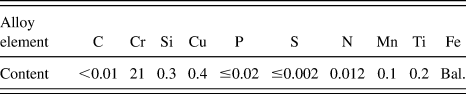
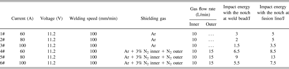
3 mm thick high chromium low carbon 443 ferritic stainless steel sheets were prepared for the investigation with the dimensions of 200 × 60 × 3 mm. The chemical compositions and properties of the material are listed in Tables I and II, respectively. To explore the effect of nitrogen gas as a composition in shielding gas on ferritic stainless steel arc welding, autogenous gas tungsten arc welding (GTAW) was used under several conditions shown in Table III.
Chemical compositions of 443 ferritic stainless steel (wt%).

Properties of 443 ferritic stainless steel.

Welding parameters and impact energy.
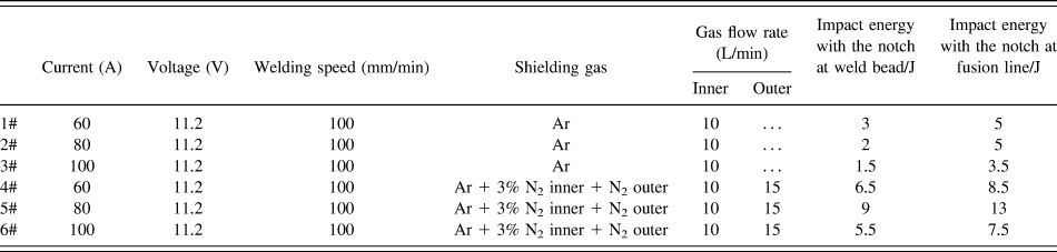
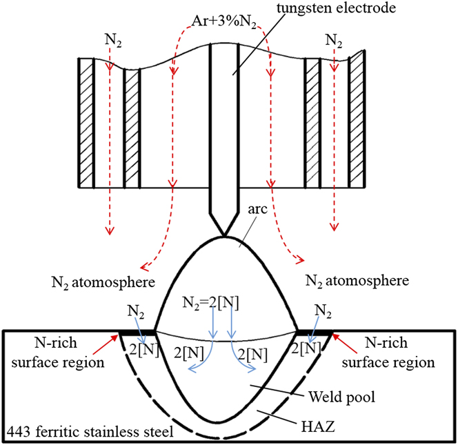
Figure 1 shows the experimental schematic diagram. A small number of nitrogen gas was added to the Ar-based shielding gas forming the argon and nitrogen mixture via a gas mixer. Then the inner layer shielding gas was formed. The inner gas is mainly used to protect welding molten pool. The outer layer gas was pure nitrogen gas via a cover fixed on the GTAW torch to achieve the aim to protect the HAZ. Abundant preliminary experiments indicated that the proportion of the nitrogen in mixed gas is less than 5%, or the welding arc is unstable, and the mechanical property of the welded joints also decreased. As thus, according to the preliminary exploration, the nitrogen content in the inner argon-based shielding gas was 3 vol% in this study. In this research, the power source was Times WS-250 with direct current electrode negative polarity. Before welding, the specimens were polished by sandpaper to remove stainless steel oxide layers and cleaned by acetone and alcohol.
Schematic diagram of double-layer shielding gas welding.

The microstructure and cross-section of the joints were observed via an optical microscope (OM). Homemade metallographic corrosion fluid was FeCl3 (5 g) liquid with HCl (15 mL), and deionized water (15 mL). The welds were etched for about 15 s. Vickers microhardness was measured about 0.5 mm distance from the weld surface under a load of 300 N. Two adjacent indentations are 0.5 mm apart. Charpy impact testing was performed to test the toughness of the joints at room temperature. The dimensions of Charpy V-notch specimen were 55 × 10 × 3 mm. at V-notch was the center of the weld seam and the fusion line to measure the impact energy of the welds and HAZ, respectively. The impact fracture surfaces and the cross-section of the fracture were analyzed by a scanning electron microscope (SEM) equipped with energy dispersive x-ray spectroscopy (EDS). The microstructure of weld surface near the V-notch was observed by OM to show the path of crack propagation.
In the process of the experiment, 80 A was found to be a relatively appropriate current. To make it easier to express the different role between pure Ar shielding gas and nitrogen addition shielding gas, 2# and 5# specimens were selected because of its representativeness referred as condition 1 and condition 2, respectively to discuss the role of nitrogen in improving the toughness of the 443 ferritic stainless steel welded joints.
III. RESULTS AND DISCUSSION
A. Macrostructure
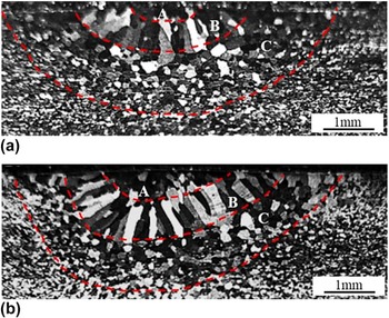
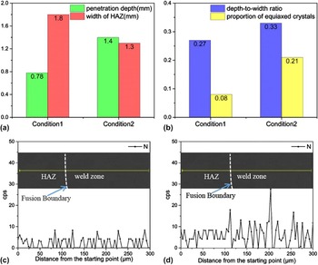
Figure 2 shows the cross-sections of the welded joint protected under condition 1 and condition 2, respectively. A dissymmetry was produced on the cross-sections of the weld under condition 2 as shown in Fig. 2(b). Figure 3(a) shows the effect of nitrogen addition on the weld penetration depth and the width of HAZ. Figure 3(b) shows depth-to-width ratio of the weld metal and proportion of equiaxed crystals in welds. It is quite clear that weld penetration depth and depth-to-width ratio of the weld metal both increased with nitrogen gas addition in Ar-based shielding gas. The weld penetration depth increased from 0.8 to 1.4 mm. The depth-to-width ratio of the weld metal is increased from 0.25 to 0.37. The semblable conclusions have been reached. Reference Huang16,Reference Lin and Chen17 Much more equiaxed crystals were produced and the width of HAZ is narrower when protected by double layer gas with nitrogen gas addition. The proportion of equiaxed crystals in welds was 8% (condition 1) and 21% (condition 2), respectively. The width of HAZ is 1.8 mm (condition 1) and 1.2 mm (condition 2), respectively. The phenomenon was related to the behavior of nitrogen in stainless steel.
Cross-sections of the welded joint: (a) condition 1; (b) condition 2. (A): equiaxed zone, (B): columnar zone, (C): HAZ.

(a) HAZ width and proportion of equiaxed grain; (b) weld penetration depth and depth-to-width ratio; (c) distribution of nitrogen from weld-seam to HAZ under condition 1; (d) distribution of nitrogen from weld-seam to HAZ under condition 2.

Nitrogen from the shielding gas will react with the ferritic stainless steel during welding. Two patterns happened in the dissolution of diatomic nitrogen gas in the metal reaction when welding. Firstly, diatomic gas molecules were absorbed by the metal surface then was decomposed into atoms. The atoms dissolve in the deep-layer of the metal through the surface. Dissolving reaction in the metal can be represented as follows.
 $${{\rm{N}}_2} = 2\left[ {\rm{N}} \right]\quad .$$
The solubility of N in the metal accords with the square root law.
 $$S\left( {\rm{N}} \right) = K\left( {{{\rm{N}}_2}} \right)\sqrt {p\left( {{{\rm{N}}_2}} \right)} \quad .$$
Where, K(N2) is the equilibrium constant of dissolving reaction and p(N2) is the nitrogen partial pressure in gas phase. Actually, part of nitrogen gas had been already decomposed in high temperature arc. The dissolution of N belongs to the pattern of monatomic dissolution.
 $${\rm{N}} = \left[ {\rm{N}} \right]\quad .$$
The solubility of N in the metal accords with the linear rule.
 $$S\left( {\rm{N}} \right) = K\left( {\rm{N}} \right)p\left( {\rm{N}} \right)\quad.$$
Where, K(N) is the equilibrium constant of dissolving reaction and p(N) is the nitrogen partial pressure in gas phase. Faster heat dissipation on arc periphery resulted in less decomposition of nitrogen gas. Thus, the nitrogen in outer layer was absorbed by the metal mainly in the form of atoms. This part of the nitrogen atoms was added into the HAZ in the form of diffusion. Nitrogen gas in the inner layer and a small number of the nitrogen gas in the outer layer were decomposed in the high temperature arc. This part of N dissolved into the weld pool accompanied by the metal melting. Figures 3(c) and 3(d) show the average content and concentration changing of nitrogen elements measured by EDS across the fusion boundary. The analysis of the EDS implies that the average content of nitrogen was higher with nitrogen gas addition into the Ar-based shielding gas. It can be concluded that weld zone contains more N element.
N element coming from the decomposing of nitrogen gas in high temperature arc dissolved into the welding molten pool, which changed the conduction state of anode surface. This suggests that a swing in the center of the arc was caused via the change with the nitrogen gas addition into the shielding gas, which caused the dissymmetry. Electromagnetic pinch force increased with diatomic nitrogen gas addition in shielding gas. As a result, the welding arc was shrunken. Shrunken arc has higher energy density, which contributed to produce more equiaxed crystals in welds and reduce the width of HAZ. Deeper penetration weld was consequently produced. The depth-to-width ratio of the weld metal is increased. In general, the temperature gradient in the boundary of weld pool is great, which led to a significant development of columnar crystals. Nitrogen dissolving in the weld pool changed the solute distribution, which made constitutional supercooling significant and reduced the temperature gradient of the weld pool. Thus, the growth of columnar crystals was controlled, and equixed grain is increased.
B. Microstructure
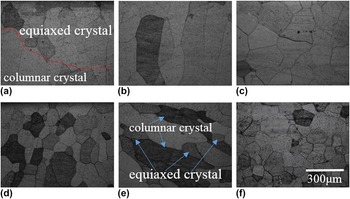
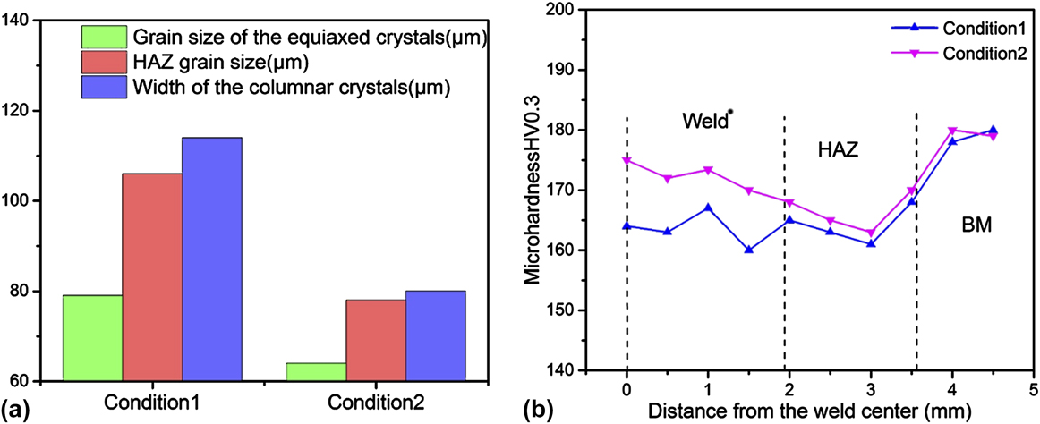
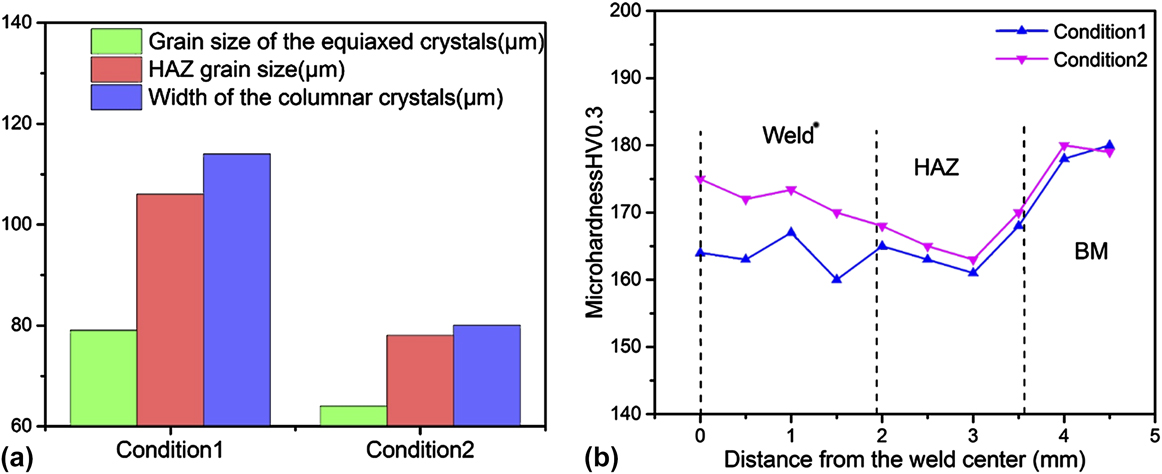
Figure 4 exhibits the microstructure in welds and HAZ under condition 1 and condition 2. A significant decrease can be seen in the average grain size of the equiaxed crystals [Figs. 4(a) and 4(d)], the average width of the columnar crystals [Figs. 4(b) and 4(e)] and HAZ grain size [Figs. 4(c) and 4(f)] under condition 2. Figure 5(a) shows the effect of nitrogen addition on grain size of the equiaxed crystals, HAZ grain size and width of the columnar crystals. The average grain size of the equiaxed crystals is 79 μm (condition 1) and 64 μm (condition 2), respectively. HAZ grain size is 106 μm (condition 1) and 78 μm (condition 2), respectively. The average width of the columnar crystals is 114 μm (condition 1) and 80 μm (condition 2), respectively. In addition, some equiaxed crystals were also distributed among the broken columnar crystals [Fig. 4(f)] under condition 2. The microstructure changed significantly due to the difference between two different shielding gas.
Microstructure in welds and HAZ: condition 1 (a), (b), (c); condition 2 (d), (e), (f). Equiaxed crystals; (a), (d); columnar crystals: (b), (e); HAZ: (c), (f).

(a) Effect of nitrogen addition on grain size of the equiaxed crystals, HAZ grain size and width of the columnar crystals. (b) Microhardness of the welded joint.
Thermal conductivity of nitrogen gas is larger than argon, and decomposition of diatomic nitrogen gas was an endothermic process. As a result, a more rapid cooling was produced in welds under condition 2, which promoted grain refinement. In addition, the second phase particles TiN [Fig. 7(d)] also played an important role in grain refinement. Decomposed N dissolved into the workpiece including welds and HAZ. N combined with Ti formed the second phase particles TiN which was regarded as the nucleating agent to refine the grains. At the same time, grains size decreased.
Figure 4(e) shows a fine microstructure. Some fine grain size equiaxed crystals are distributed in columnar crystals zone. In the process of forward extension of the columnar crystal in welds, dendrites may be cracked by arc when welding especially protected in double layer gas. Arc welding protected under diatomic gas (nitrogen) addition shielding gas has higher energy density. Thus, columnar crystal was more likely to be broken by arc. Precipitated TiN particles in weld pool were regarded as new nucleation sites. Few equiaxed crystals were formed discretely distributing among the broken columnar crystals.
C. Microhardness
Figure 5(b) exhibits the effect of nitrogen on microhardness of the welded joint. In both cases, the microhardness change trend is consistent. The hardness of HAZ was the lowest. Microhardness in welds is slightly above than that in HAZ but inferior to that in base metal. Compared with condition 1, microhardness under condition 2 in welds and HAZ both increased, which means nitrogen gas addition to the shielding gas increased the Vickers hardness. Similar conclusions are obtained according to previous investigations on stainless steel welding. Reference Huang16
Here, the microhardness change trend was determined by grain size. Smaller grain size leads to a higher microhardness. Thus, according to the grain size in welds, HAZ and base metal, the highest microhardness was in base metal. Microhardness in HAZ is minimum because of its coarsest grain. Adding nitrogen gas into the Ar-base shielding gas led to nitrogen dissolving into the specimen, which broke the balance between atoms in ferritic stainless steel. Lattice distortion was intensified causing higher hardness under condition 2. Reference Shankar, Gill, Mannan and Sundaresan18,Reference Akhlaghi, Steiner, Meka, Leineweber and Mittemeijer19
D. Fracture morphology and toughness
Table III shows the results of the Charpy impact energy at room temperature. It was observed that the toughness was better improved with nitrogen gas addition into the Ar-based shielding gas. It was improved from 2J to 9J (welds), 5J to 13J (HAZ).
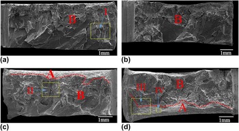
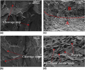
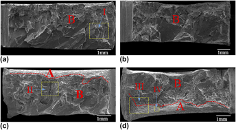
Figure 6 exhibits the cross-sections of the macroscopic fracture of the Charpy impact specimens. Area A and B are on behalf of the ductile fracture zone and brittle fracture zone, respectively. Figures 6(a) and 6(b) are the fracture cross-sections of welds and HAZ under condition 1, respectively. The fracture surface of the ferritic stainless steel welded joint was mostly occupied by brittle fracture zone made up of large amounts of cleavage steps. This is typical fracture characteristics of ferritic stainless steel welded joint. Reference Mallaiah, Reddy and Kumar4 Figures 6(c) and 6(d) exhibit the fracture cross-sections of welds and HAZ under condition 2, respectively. Distinct phenomena was produced between condition 1 and condition 2. Under condition 2, the brittle fracture zone was produced either, but the size of the area was cut down. Less cleavage steps were produced. The size of cleavage facets is the factor that determines the brittle fracture energy. Reference Fattahi, Nabhani, Vaezi and Rahimi20 As described in previous sections, fracture of ferritic stainless steel welded joint is basically brittle fracture. Ductile fracture zone was produced about 0.3–0.5 mm thickness distance from the weld surface [Area A in Figs. 6(c) and 6(d)] with nitrogen addition to Ar-based shielding gas. Abundant equiaxed dimples were produced in this thickness.
Cross-sections of the macroscopic fracture of welds and HAZ: (a) and (b) of welds and HAZ, respectively under condition 1; (c) and (d) of welds and HAZ, respectively under condition 2; (A) and (B) represent ductile fracture area and brittle fracture area, respectively.

Figure 7 is the SEM micrographs obtained from the fracture surfaces as shown in Fig. 6 I–IV. Figures 7(a) and 7(b) exhibit the cleavage steps features under condition 1 and condition 2, respectively. Obviously, the size of cleavage steps is smaller under condition 2. Figures 7(c) and 7(d) exhibit the ductile fracture features under condition 2. Large number of equal-axis ductile voids were produced on ductile fracture zone. Second phase particles were found on the bottom of the equal-axis ductile voids [Fig. 7(d)].
(a-d) High magnification fractographs as indicated by rectangles in Figs. 6(a), 6(c), and 6(d) above.

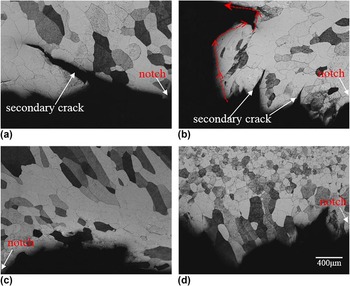
Figure 8 shows the path of crack propagation in different location of welded joint under condition 1 and condition 2, respectively. The notch was located in weld center [Figs. 8(a) and 8(c)] and fusion line [Figs. 8(b) and 8(d)] under condition 1 and condition 2, respectively. As can be seen from Fig. 8(a), the crack propagated linearly, and that a long secondary crack was created. The secondary crack also propagated straightly to coarse columnar zone. This indicated that the coarse grain exhibited low resistant to crack propagation, which promoted the brittle fracture. Reference Díaz-Fuentes, Iza-Mendia and Gutiérrez21,Reference Li, Ma, Subramanian, Misra and Shang22 The crack propagated in a flexural fashion in the surface of fracture sample seen from Fig. 8(c) shows fine toughness of welds under condition 2. The secondary crack was also produced in HAZ under condition 1 seen from Fig. 8(b). Beyond that, the direction of crack propagation was changed a lot. After two small secondary cracks occurred, the crack propagate perpendicular to the original direction. Then the propagation direction is returned to the beginning crack propagation direction. In this process, the crack is propagated straightly, which brought a bad toughness. Compared with Fig. 8(b), fracture is more uniform and secondary crack was not produced. This indicated that toughness was better under condition 2.
Path of crack propagation in different location of welded joint: (a) and (b) of welds and HAZ, respectively under condition 1; (c) and (d) of welds and HAZ, respectively under condition 2.

Second phase particles make it easy to form stress concentration in the workpiece, and the stress concentration contributes to the formation of ductile voids. In the previous exposition, N element dissolving into the ferritic matrix with nitrogen addition produced second phase particles (TiN). Hence the number of the ductile voids increased under condition 2. In the process of fracture, when second phase evenly distributed in the matrix phase, alloy deformation resistance increased. Thus, specimens need to absorb more energy to fracture. As a result, the value of the impact toughness under condition 2 was higher than that under condition 1.
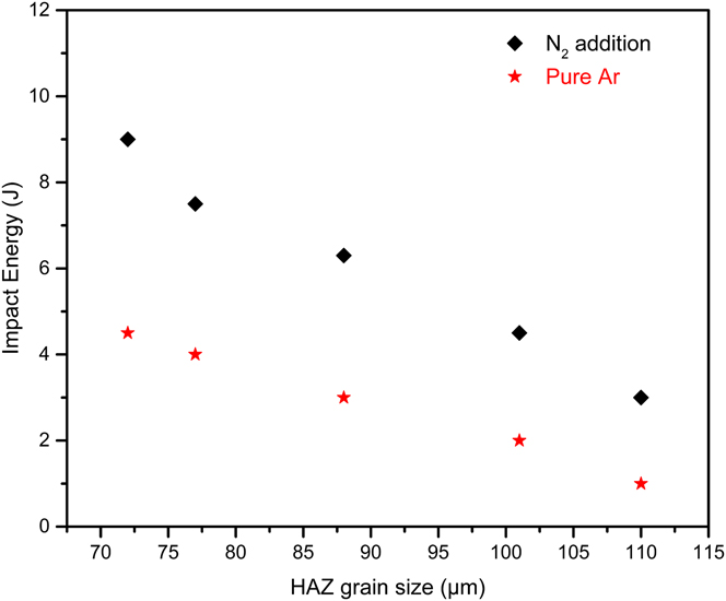
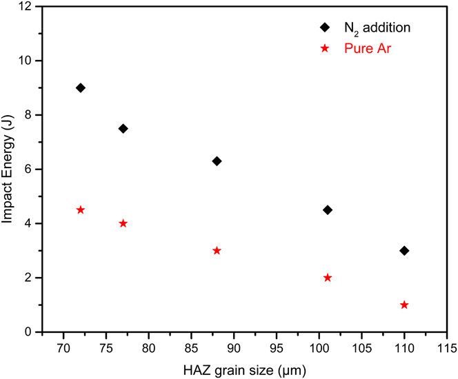
In a general way, grain refinement is a widely adopted method to improve the toughness. Reference Kang, Li, Yuan and Wang23,Reference Kaijalainen, Suikkanen, Limnell, Karjalainen, Kömi and Porter24 In addition, toughness is related to other factors including chemical elements. Figure 9 shows the relationship between grain size and impact toughness in HAZ. Impact energy at room temperature was compared with nitrogen addition and without under approximate equivalent grain size. Under the condition of approximate equivalent grain size, toughness was higher with nitrogen addition. The chemical composition of the specimen was changed by the nitrogen addition. It means that on the basis of grain refinement, toughness was further improved with nitrogen addition.
Relationship between grain size and impact toughness in HAZ.
IV. CONCLUSIONS
In this study, the role of nitrogen gas in Ar-based double layer shielding gas on impact toughness improvement of 443 ultra-pure ferritic stainless steel welded joint was explored. Main conclusions were obtained as follows:
-
(1) Additional nitrogen led to N element addition into both welds and HAZ of the ferritic stainless steel welded joints. The proportion of equiaxed crystals in welds increased by 1.6 times. The width of HAZ decreased by 50%. The weld penetration depth and depth-to-width ratio of the weld metal is increased by 75% and 48%, respectively.
-
(2) The average grain size of the equiaxed crystals and HAZ grain size decreased by 18.9% and 26.4%, respectively. The average width of the columnar crystals decreased by 29.8%. Microhardness of welds and HAZ increased.
-
(3) The toughness was dramatically enhanced with the help of nitrogen gas addition into the Ar-based shielding gas. It was improved by 3.5 times (welds), 1.6 times (HAZ). On the basis of grain refinement, HAZ toughness was further improved with the change of chemical composition.
-
(4) With nitrogen addition, ductile fracture zone was produced about 0.3–0.5 mm thickness distance from the weld surface obtained from the cross-sections of the fracture.
ACKNOWLEDGMENTS
This work was supported by the National Natural Science Foundation of China under Grant (No. 51305291), International Science & Technology Cooperation Program of China (2014DFR70280), and Natural Science Foundation of Shanxi Province (No. 201302121-1).