


1. INTRODUCTION
Positioning in the urban environment is still a great challenge for navigation systems. Position accuracy in such environments is significantly degraded, and in many areas, it is not possible to obtain a GPS position fix at all. There are currently two promising methods that can be used to address the problem of accurate positioning in the urban environment: GPS integrated with dead reckoning, and High Sensitivity GPS (HSGPS).
Dead reckoning is the process of updating position based on speed and direction. One form of dead reckoning that is becoming more widespread is Inertial Navigation Systems (INS). Recent advances in Micro-Electro-Mechanical Sensor (MEMS) technology mean that small, lightweight, low power, low cost sensors have become available for applications such as urban navigation. It is well known that the characteristics of GPS and INS are complementary: the INS provides continuous positioning that drifts over time, whereas GPS measurements do not drift, but are not continuously available. The main problem with low cost MEMS sensors is the relatively poor performance compared to other inertial technologies such as ring laser or fibre-optic gyros. Therefore, in order to be useful, MEMS sensors have to be augmented with other positioning technologies such as GPS in order to restrict the rapid drift that would otherwise occur. The performance of GPS and INS integrated systems is highly dependent on the quality of the sensors used, and the availability of GPS measurements to restrict the drift of the INS.
Another technology that has emerged in the last few years for positioning in areas where it is difficult to acquire and track GPS signals is HSGPS. HSGPS receivers are capable of tracking signals that are 20 to 30 dB weaker than the typical signal strengths experienced outdoors. The minimum received GPS signal level for clear conditions is defined as −160 dBW for the L1 coarse/acquisition code (Watson, Reference Watson2005), whereas modern HSGPS receivers can typically track down to levels of better than −180 dB. To put this into context, one layer of brick will typically attenuate a GPS signal by 5 dB, 100 mm of concrete typically attenuates the signal by 14 dB, and thick steel reinforced concrete typically attenuates by 29 dB (QinetiQ, 2004). Therefore HSGPS receivers can track signals even in many buildings. As a result of attempting to track signals at such weak signal levels, the signals recorded by HSGPS receivers are typically corrupted by significant multipath error. Therefore, HSGPS receivers sometimes can only use signals that contain multipath which reduces the achievable position accuracy.
There are a number of applications that require high accuracy positioning in the urban environment. Vehicle and pedestrian navigation applications require positioning technology that can operate in areas with restricted satellite availability for long periods of time. For these applications, the technology is also required in real-time. Other applications that may require a relatively low cost navigation system for continuous and accurate positioning include surveying, inventory management, terrestrial geo-referencing for photogrammetric or laser scan surveys, vehicle performance testing and vehicle tracking. Some of these applications do not necessarily require a real-time solution, therefore this paper also considers the case of using GPS and low cost INS integration in post processing.
This paper investigates the positioning performance of a GPS and low cost INS system compared to a HSGPS operating in a typical urban environment in the UK. The urban environment is particularly challenging for GPS and INS sensors due to the infrequent measurement updates that are available. This problem is addressed by directly integrating the GPS measurements with an INS in the so-called tightly coupled integration algorithm. This algorithm greatly increases the number of measurements that are available to update the INS by still using satellite measurements when there are 3 or fewer satellites in view. The use of GPS and INS integration using post processing is also considered for applications that do not require a real time solution. The paper compares the performance of the GPS and low cost INS to a HSGPS receiver to identify the different characteristics of each type of sensor.
2. POSITIONING TECHNOLOGY
2.1. High Sensitivity GPS
HSGPS receivers are typically capable of tracking signals that are up to 30 dB (1000 times) weaker than the typical signal strengths experienced outdoors. High sensitivity GPS receivers use coherent or non-coherent integration techniques to improve sensitivity. Non-coherent integration is restricted to an integration time of 20 ms, however coherent integration can be used to extend integration times beyond 20 ms. The length of the coherent integration time period is restricted mainly by the uncertainty in the Doppler frequency over the time interval (Watson, Reference Watson2005). This is caused by factors such as vehicle dynamics, clock drift and ephemeris errors which means that integration times are generally restricted to less than 1 second (ibid.). Two approaches are used to achieve the long coherent integration times: a DSP approach, and a hardware approach (van Diggelen, Reference van Diggelen and Abraham2001). The DSP approach is known as the store-and-process approach where the integration is achieved in the frequency domain using an FFT. Other GPS receivers use a multiple hardware correlator approach where thousands of correlators can be implemented on a single low power chip (ibid.).
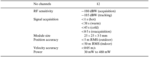
An example of one of the current HSGPS receivers is the QinetiQ Q20, the specification of which is given in Table 1. The table shows that the QinetiQ receiver is capable of acquiring signals at −180 dBW and is capable of tracking signals at −185 dBW. An additional advantage of HSGPS is that initial satellite acquisition is also greatly accelerated with the receiver even capable of acquiring satellites within 45 s from a cold start. The initial acquisition of signals using the QinetiQ receiver is not, however, considered in this paper. Instead, this paper will look at the tracking and navigation performance of the QinetiQ Q20 in the urban environment.
QinetiQ Q20 GPS receiver specification (QinetiQ, 2004).
2.2. GPS and low cost INS integration
It is well known that GPS and INS measurements can be combined at different integration levels usually known as loose, tight and deep integration (Hide, Reference Hide2003). Generally, a Kalman filter is used to combine the measurements which makes use of the stochastic and dynamic properties of the two systems. Commonly, GPS and INS sensors are integrated using the loose integration algorithm where a navigation solution from a GPS receiver is used to correct the INS errors. This approach is generally used due to the simple implementation requirements. However, there is a significant improvement that can be made to this approach by using the tight integration algorithm when there are significant periods of obstructed GPS measurements, such as those experienced in urban environments. The tight integration algorithm uses a single Kalman filter to integrate the GPS and INS measurements which is shown in Figure 1. This is referred to as tight integration because the IMU measurements can also be used to aid the GPS processing. The figure shows that raw measurements are collected from the IMU, and the measurements are converted to position, velocity and attitude measurements in the desired coordinate system using the INS mechanisation algorithms. The position and velocity is then used to form predicted range measurements (corrected for the lever arm offset from the GPS antenna to the INS) to each of the satellites. These ranges are then used with the GPS raw pseudorange measurements to estimate the INS errors using a single integration filter. The principal advantage of this approach is that GPS measurements can still be used to aid the INS when less than four satellites are available. For the urban environment, this means that there will be a greater number of measurements used to update the INS which should reduce the position error growth during periods with fewer than four satellites in view.
Centralised GPS/INS filter.

A further extension to the standard Kalman filter is the Kalman filter smoothing algorithm (Gelb, Reference Gelb1974, Brown and Hwang, Reference Brown and Hwang1997). Smoothing is a post-processing algorithm that is generally used when all of the data collected by the navigation system has been recorded. Therefore smoothing cannot be used in real-time which significantly restricts the number of applications in which it can be used. Smoothing can, however, offer a significant improvement in the position estimation in an integrated GPS/INS, particularly when there are frequent periods of fewer than four GPS measurements. Figure 2 shows the principle of smoothing during a period of restricted satellite availability where the INS position error grows with time in both the forward and reverse filters. When the smoothing algorithm is applied to the data, the error is significantly reduced across the data outage interval with the maximum error occurring in the middle of the obstructed period. The figure shows that Kalman filter smoothing offers the potential for a significant improvement in the estimation error over the conventional forward-only approach. Furthermore, it can be demonstrated that the smoothed mean square estimation error will always be less than or equal to the forward-only solution (Gelb, Reference Gelb1974).
Kalman filter smoothing error during outage (adapted from Gelb, Reference Gelb1974).

One further possibility to improve the usefulness of the smoothing algorithm is that it can also be operated in near-real time when a time-lag in the output of the data is not a problem (Shin and El-Sheimy, Reference Shin and El-Sheimy2002). For example, after a period of obstructed GPS signals, the algorithm can be used to recompute the position solution. The time lag period does not have to be fixed so the smoothing algorithm could be applied as required. However, if a near real-time algorithm such as this is used, the position error will still be larger than the full combined forward and reverse filter when all the data has been collected. This is due to the improved error estimation of the inertial sensor errors from using data over the entire dataset. More information on the implementation of the Kalman filter smoothing algorithm used for this paper can be found in Hide and Moore (Reference Hide and Moore2005).
3. FIELD TRIAL
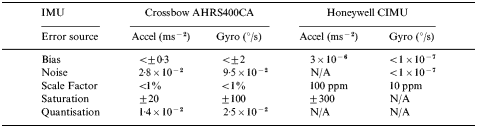
A field trial was conducted in February 2005 in Nottingham, UK, to test the performance of the positioning technologies described in the previous sections. A Crossbow AHRS400CA IMU was used as a typical low cost IMU. The sensor is approximately five years old and is considered to be of equivalent performance to IMUs that are currently available for less than £2000. The performance of the IMU is described in Table 2. The IMU was integrated with a NovAtel OEM4 GPS receiver using L1 pseudorange and Doppler measurements, with a reference station located at the IESSG building in Nottingham (with the maximum baseline for the trial less than 5 km). A much lower cost GPS receiver could potentially be used instead of the NovAtel receiver which would mainly result in increased pseudorange measurement noise. Trials are currently being conducted to identify the impact on the positioning performance of the integrated system. The IMU was located on the floor in the rear of the test vehicle, with the lever arm separation between the GPS antenna and IMU measured with a total station. A QinetiQ Q20 HSGPS receiver was used with the antenna located on the roof of the vehicle in a location that was slightly obstructed by one of the other GPS antennas installed on the vehicle. The location of the IMU and GPS receivers is shown in Figure 3. It should be noted that the QinetiQ receiver used in the trial contained a 2004 firmware version, therefore it should be noted that current commercial firmware is likely to provide different performance.
a) Total station survey to measure lever arm separation between GPS receiver and IMUs, b) Location of GPS receivers.

The University of Nottingham’s Applanix POSRS system was also installed on the vehicle in order to provide a reference position solution to compute the position error of the other sensors. The Applanix POSRS is a high performance GPS and INS integrated system that uses a NovAtel OEM4 GPS receiver integrated with a navigation grade Honeywell CIMU. The data from the POSRS was post-processed using the Applanix POSPac GPS/INS integration software to provide the reference position solution. POSPac uses the loosely coupled GPS and INS integration algorithm, and the software was configured so that only GPS measurements with resolved ambiguities were used. The POSRS uses a high performance IMU to bridge periods of GPS outages without a significant degradation in positioning performance. The performance of the Honeywell and Crossbow IMUs are described in Table 2.
Crossbow AHRS400CA and Honeywell CIMU specification.
3.1. Test route
A test route was driven that incorporated a range of urban conditions shown in Figures 4 and 5. The route was devised to incorporate conditions from relatively clear GPS areas, to semi-obstructed surroundings in suburban locations, to deep urban conditions where there is a significantly restricted sky view. The test route was driven twice and each loop took approximately 25–30 minutes. The results presented in this paper are for the second of the two loops due to a problem with logging the data from the HSGPS.
Vehicle trajectory.

Images from around the test route (clockwise from top left) a) clear sky for initialisation, b) semi-urban, c) trees, d) dense urban.

One of the operational requirements for the low cost INS is that a short alignment period is required to initialise the inertial sensor errors, and to identify the initial roll, pitch and yaw of the vehicle. To achieve this, the vehicle was kept stationary in a car park with a clear view of the sky to obtain the initial position using GPS. The vehicle remained static for 1 minute to compute the average gyro output which was used to give initial values for the gyro bias states. An initial heading estimate was obtained from the GPS derived velocity of the vehicle before the static initialisation. The vehicle was then driven around the car park for five minutes to achieve a dynamic alignment to initialise the attitude and bias states in the Kalman filter. The alignment of the INS is a significant problem for many applications where such requirements are impractical.
3.2. Navigation software
The University of Nottingham’s KinPosi software was used to process the measurements from the GPS and low cost INS integrated system. KinPosi provides the loose and tight coupled filtering approaches described earlier in this paper. The software also provides the Kalman filter smoothing using the RTS algorithm as described in Gelb (Reference Gelb1974)and Hide and Moore (Reference Hide and Moore2005). A 15 state Kalman filter was used to model the INS errors with three states each for position error, velocity error, attitude error, gyro bias error and accelerometer bias error. The values used for the initial covariance and process noise in the Kalman filter were previously estimated from prior trials and no additional tuning was required. Differential pseudorange and Doppler measurements were used as measurements to restrict the INS drift using the tight integration Kalman filter algorithm described earlier in this paper. The navigation solution for the QinetiQ Q20 receiver was computed in real-time internally by the receiver, with the data made available over a serial connection using the NMEA 0183 standard.
3.3. Satellite availability
Figure 6 shows the satellite availability during the trial for the Novatel and QinetiQ receivers; this data is summarised in Table 3. Figure 6a shows that the number of satellites recorded by the NovAtel receiver varies continually between 0 to 8 satellites throughout the trial. The figure does not show periods where there is only one satellite in view since the Kalman filter uses double differenced measurements, hence any periods with one satellite in view are shown as zero. From Table 3, it is clear that there are fewer than four satellites available for 51·6% of the time. Therefore significant periods are experienced where there are no measurements available to update the INS if the loosely coupled integration algorithm is used. Instead, by using the double differenced tight integration approach, easurements are available for a further 40·1% of the time.
Satellite availability during Nottingham trial for a) NovAtel OEM4, b) QinetiQ Q20.

Satellite availability during Nottingham trial.

Figure 6b shows the satellite availability for the QinetiQ HSGPS receiver. Here it is shown that there are only two epochs in the entire 30 minute period where there are fewer than four satellites in view. Therefore, a position solution is available for almost the entire trial. From comparison of Figures 6a and 6b, it is not necessarily clear that the data was collected during the same period. This is thought to be as a result of the significant impact that tree cover has on GPS availability for the NovAtel receiver, whereas the QinetiQ receiver appears to be unaffected by tree cover. For example, the obstructions that occur during the period between 1400 and 2000 seconds is thought to mainly be a result of tree cover.
3.4. Synchronisation
An additional issue that had to be considered during the analysis of the data was the synchronisation between the different navigation solutions. All systems output a position solution relative to GPS time which simplifies the synchronisation. However, the QinetiQ Q20 reports an NMEA solution every 2·048 seconds which meant that it was important to ensure that the Q20 and reference data was synchronised since the Q20 output does not always coincide with the exact GPS second. This was relatively easy to achieve using the POSRS reference since it provides a position solution at 200 Hz. However, since the 200 Hz data results in very large file sizes, the POSRS data was output at 100 Hz, resulting in an estimated 5 ms maximum synchronisation error. Assuming that 5 ms is the maximum synchronisation error, and considering that the maximum speed of the vehicle was approximately 15 m/s, the maximum error caused by synchronisation should be approximately 7 cm which is significantly less than the expected accuracy of the QinetiQ receiver.
In order to verify the synchronisation of the two systems, the error was recomputed for different time offsets between the QinetiQ Q20 and Applanix POSRS solutions. The results are shown in Figure 7 for the position error in the north and east axes. It is clear from the figure that the minimum error occurs at a time offset of −0·5 s. In other words, there is an apparent time lag of 0·5 s from the QinetiQ receiver. A similar time lag is apparent in the speed and heading data from the receiver but not in the height data which is thought to be as a result of the lower accuracy height solution described later in this paper. In the following sections, all errors are accounted for in the 0·5 s time lag in order to identify the best performance available from the receiver. It should be noted that for applications that require a real-time solution, this time lag will introduce the additional error shown in Figure 7.
Position error for different time lags.

4. RESULTS
Figure 8 shows the horizontal positioning error for the GPS and low cost INS, and QinetiQ HSGPS solutions. The data is given for a period of 1800 seconds (30 minutes) which corresponds to the second circuit around the route shown in Figure 4. Figure 8a shows two solutions from the GPS/INS: the red line shows the real time position solution, and the green line shows the solution that can be achieved using the Kalman filter smoothing algorithm in post processing. In real-time, it is clear that when sustained periods of GPS obstructions occur, the position error grows with time. During the trial, a maximum position error of approximately 11 metres occurs in the forward solution. The INS solution still requires that there are at least four GPS measurements available in order for the INS position error to become fully observable, therefore, if there are sustained periods of reduced GPS measurements (such as if a vehicle were to enter a multi-storey car park) then the position error is likely to grow without bound. In this circumstance, it would be necessary to add further measurements to the Kalman filter such as zero velocity updates when the vehicle is stationary to reduce this drift. This is potentially a significant problem with low cost GPS/INS systems where the position error can increase rapidly.
Horizontal position error for a) GPS and low cost INS, b) QinetiQ Q20.

Figure 8a also shows the smoothed GPS/INS solution that was computed in post processing when all of the data had been recorded. Here, it is clear that the maximum position error is significantly reduced since the filter makes use of data before and after the outage which effectively reduces the period of time over which the INS has to operate without any measurement updates. Furthermore, other error sources such as inertial sensor errors should also be better estimated using the smoothed filter which should improve the performance of the INS during periods of restricted GPS availability. GPS and INS integration is particularly suited to Kalman filter smoothing, especially when there are frequent GPS outages, however, it is obvious that this greatly restricts the number of applications in which the system can be used. The alternative is that the smoothing algorithm could be applied in near real-time. For example, in the presence of a long period of GPS obstructions, the measurements could be logged so that once more than four GPS measurements return to view, the smoothing algorithm can be applied to significantly reduce the position drift. Although such a system is not directly suited to navigation applications, it could be applied to applications such as road user charging. In such applications, high accuracy navigation is necessary, whereas the position solution is only required in near real-time.
Figure 8b shows the position error obtained from the QinetiQ Q20 HSGPS receiver for the same time period. Firstly it should be noted that the GPS receiver is operating in standalone mode compared to the GPS/INS system that operates differentially using a reference receiver, therefore, the position solution will be comparatively degraded due to effects such as atmospheric errors. It is clear from the figure that the majority of horizontal positions are at the level of 10 m or better, and furthermore, a position solution is available at all times throughout the trial except for two epochs. This is compared to the 48·4% of epochs where a position solution is available using the conventional geodetic receiver. However, the figure also shows that there are periods where large errors occur, for example at approximately 2280 seconds there is a significant position error of over 70 m. These periods are likely to occur when only measurements that are significantly affected by multipath are available to the filter. Generally, the QinetiQ receiver is very effective at removing measurements with significant multipath errors from the navigation solution, however occasionally it is likely that there will be periods where all measurements are corrupted with multipath (such as indoors) or there is not a sufficient number of measurements to effectively identify which measurements to remove from the solution. More details on measurement weighting schemes and outlier removal can be found in, for example, Lachapelle (Reference Lachapelle, Kuusniemi, Dao, MacGougan and Cannon2003).
Figure 9 shows the horizontal position error for the GPS/INS and HSGPS solutions for the 300 second (5 minute) period starting at 2200 seconds where there is a significant period of obstructed GPS measurements. Figure 9a shows the position solution from the GPS/INS for the forward and smoothed solutions. Here it is shown that there is a period of over 100 seconds starting at 2320 seconds where three or less satellites are in view. During this period, it is apparent that the real-time position error grows to a maximum of approximately 11 m before four satellites come back into view. For the smoothed solution, the position error is reduced to a maximum of 2 m which is a significant improvement for applications that can be operated in post processing. Figure 9b shows the position accuracy from the QinetiQ receiver for the same period. It is clear that where the position error of greater than 70 m occurs, there are seven or more satellites in view. Furthermore, there is a position error of greater than 30 m that occurs at approximately 2470 seconds where nine satellites are in view. During this same period, the NovAtel receiver is able to track five satellites, which results in a differential position error of significantly less than 1 m. Although the HSGPS position error can occasionally be quite significant due to GPS measurement errors, the QinetiQ receiver is capable of providing continuous measurements even in areas with significant obstructions.
Position error for a) GPS and low cost INS, b) QinetiQ Q20.

Table 4 shows the mean and standard deviation and RMS errors for position, velocity and attitude of the GPS and low cost INS integrated solution compared to the Applanix POS-RS for the Nottingham trial. The table shows that horizontal RMS errors of less than 2·5 m were experienced, whereas the vertical accuracy was better than 10 m. The poor vertical accuracy is thought to be primarily due to the weak satellite geometry, and instability of the vertical channel of the INS. The table shows that the smoothed Kalman filter was able to improve on the real-time solution by at least a factor of two. Furthermore, the maximum error experienced during the trial was reduced by five times. The table also identifies the velocity and attitude performance of the low cost INS. Again, it is clear that the vertical velocity is significantly worse than the horizontal accuracy, and the smoothing algorithm again results in a significant improvement. The statistics for the attitude measurements shown in the table identify that there are some significant biases in the attitude solution. These are assumed to be as a result of the misalignment between the Crossbow and Honeywell IMUs in the vehicle, therefore the mean error is assumed to be the misalignment between the sensors. Further trials are required to verify this. The table identifies that the yaw estimation is relatively poor compared to the high accuracy 0·08° and 0·05° standard deviations for the roll axis for real time and post processed respectively. This is a result of weak observability of the yaw error in the Kalman filter and can only be improved by including additional measurements such as heading obtained from a magnetometer or dual antenna GPS receiver.
GPS and low cost INS integrated error compared to RTK Applanix POS-RS.
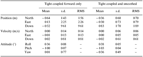
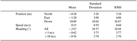
Table 5 summarises the position accuracy for the QinetiQ receiver during the Nottingham trial. The table shows that the horizontal RMS position accuracy is similar to the manufacturers quoted performance in Table 1. The receiver also outputs speed and heading in the GPRMC NMEA string. The speed measurement was identified to be 0·6 m/s RMS and the heading measurement in all conditions was greater than 28°. Since the heading measurement is derived using the velocity of the GPS receiver, Table 5 also demonstrates that heading accuracy improves with vehicle speed which is as expected.
QinetiQ Q20 HSGPS error compared to RTK Applanix POS-RS.
5. SUMMARY AND CONCLUSIONS
This paper has described the positioning characteristics and performance of two solutions for improving the positioning performance of conventional GPS positioning in the urban environment. It has been demonstrated that the GPS/INS and HSGPS technologies have different characteristics due to the positioning technology used. It was shown that the GPS and low cost INS system provided the best performance within the test area, although it should also be remembered that the GPS/INS was operating using differential GPS hence it is expected that the positioning performance during good reception should be better than standalone GPS in these conditions. It was demonstrated that the tight integration algorithm is able to provide high accuracy positioning in urban conditions, even under obstructed satellite conditions. However, for extended periods of satellite obstruction such as those potentially experienced in pedestrian navigation applications in urban conditions, GPS and INS integration is expected to be less suitable. Another limitation of the GPS/INS system is that the system requires an initial dynamic alignment in clear GPS conditions to initialise the INS. Such operational limitations are unlikely to be suitable for applications such as vehicle navigation.
This paper has also shown that the HSGPS receiver was capable of providing a position solution in all the conditions which the vehicle trial encountered. HSGPS does not have the alignment issues that are required with the GPS/INS therefore it is more convenient for applications such as vehicle navigation. However, it has been demonstrated that in certain environments where only degraded GPS measurements are available, the position accuracy can be significantly reduced with navigation errors significantly larger than those experienced with the GPS/INS. It should, however, be reiterated that the 2004 firmware used for the trial has been modified in recent versions.
It is clear from the analysis provided in this paper that HSGPS and INS provide different characteristics that provide the potential for a high accuracy, low cost navigation system that will be able to work in all environments and conditions. In order for low cost INS to work effectively, it requires constant updates from external sensors such as GPS, however for short periods, it is able to provide accurate measurements that can be used to remove periods of corrupted GPS measurements such as those experienced during the vehicle trial. Work is currently underway to investigate the performance that can be obtained from integrating HSGPS and low cost INS to overcome the limitations of the individual sensors described in this paper.
ACKNOWLEDGEMENTS
The authors would like to thank Scott Wilson Pavement Engineering for the use of their vehicle used to collect the data presented in this paper. The authors would also like to thank Sam Waugh and Jock Souter for their help with the vehicle installation.
The QinetiQ Q20 HSGPS receiver was provided by QinetiQ as part of the EPSRC-funded Pinpoint Faraday flagship collaborative research project, SPACE (Seamless Positioning in All Conditions and Environments) currently being undertaken by a consortium of eleven UK university and industrial groups. The university groups are the CAA Institute of Satellite Navigation at the University of Leeds, the Department of Civil and Environmental Engineering at Imperial College London, the Department of Geomatic Engineering at University College London (UCL), and the Institute of Engineering Surveying and Space Geodesy at University of Nottingham, and the industrial partners are The Civil Aviation Authority, EADS Astrium, Leica Geosystems, Nottingham Scientific Ltd, Ordnance Survey, QinetiQ and Thales.
The primary aim of SPACE is to undertake the basic research needed to build a prototype GNSS-based positioning system that can deliver cm-level accuracy positioning everywhere and at all times. The main component research thrusts are multipath modelling and mitigation, quality control and assessment, measurement modelling and integration, and GNSS sensor design. The key output from SPACE will be the fully tested design of a prototype plug and play integrated positioning system that can be used as a test bed for current and future positioning components and algorithms.


