


Introduction
Electrical energy storage (EES) in high-energy-density Li-ion batteries has enabled the wireless revolution with its exponential growth of portable electronic devices. Now, EES with rechargeable batteries is beginning to penetrate the transportation sector with plug-in hybrid electric vehicles (PHEVS) and with small all-electric vehicles (EVs). Large-scale stationary EES is also the most flexible option for storing economically and efficiently the electricity produced from solar, wind, and nuclear energies, especially where this storage is complemented by electrochemical capacitors.[Reference Yang, Zhang, Kintner-Meyer, Lu, Choi, Lemmon and Liu1] It is estimated that transportation and the electric grid presently account for two-thirds of the US energy use, and transportation emits distributed greenhouse gases while the grid is largely powered by coal. Therefore, EES of electricity from other energy sources than fossil fuels is essential for a sustainable future energy supply, which has prompted governments to support alternative energy technologies, including rechargeable batteries for storing electrical energy generated by wind, solar, and nuclear energies. However, to be economically competitive with fossil fuels, it has also been estimated that batteries for large-scale EES should have five times better performance and one-fifth the cost of existing Li-ion batteries.
The principal performance criteria for large-scale EES in rechargeable batteries are safety, cost, charge–discharge cycle life, amount of energy stored per cycle at a given power requirement, and environmental impact. After safety, the priority order of these criteria depends on the application. For example, gravimetric and volumetric energy densities are critical for portable hand-held electronic devices, whereas volumetric energy density is more important for batteries that power EVs. For stationary EES, cost and cycle life trump energy density. Li-ion batteries are used in hand-held electronic devices because they can provide a higher stable voltage than batteries using an aqueous electrolyte, 4 V versus 1.5 V (Fig. 1), which gives them a higher-energy density. For large-scale stationary EES, strategies other than internal storage in solid electrodes may have an advantage, e.g., storage in liquid electrodes in redox molecules soluble in a liquid electrolyte that are stored in a separate tank or in an external redox bed accessed by a gaseous molecule. However, these alternative strategies must be capable of fast charge/discharge rates and have a low fabrication and maintenance cost as well as a long calendar and cycle life.
Comparison of the energy densities of aqueous and non-aqueous rechargeable battery systems.

This perspective on a changing chemical and strategic landscape provides a summary of constraints on any battery system and of tentative experimental strategies to achieve a cost-competitive, large-scale EES in a rechargeable battery.
Constraints
A large-scale power unit contains multiple identical cells that are connected in parallel to achieve a desired current I and in series for a voltage V to deliver a desired power P = IV for a time Δt. The essential constraints of the system are those of the individual cell, which is why we focus on research of the physical and chemical design of the components of the individual cell and do not consider the problem of management of a multicell stack.
A rechargeable battery requires a reversible chemical reaction between the electrodes. Reversible electrodes may be solids or liquids, but the reactants may also be the molecules of a gas or a soluble redox species. Since the electrodes change their volume during charge and discharge, large-scale batteries can be expected to have liquid electrolytes contacting solid electrodes or solid electrolytes contacting liquid electrodes to preserve fast ionic transport across electrode/electrolyte interfaces, but liquid/liquid contacts may be used with immiscible liquids. A chemical reaction between the electrode and electrolyte needs to be avoided, but it can be tolerated where the interaction results in the formation of an interphase passivation layer that is stable and permeable to the working ion. At a solid/liquid interface, such a passivating layer is referred to as a solid–electrolyte interphase (SEI) layer where the electrolyte is the liquid.
Because ionic transport inside a cell is slow compared with the metallic electronic transport outside a cell, batteries have large-area electrodes separated by a thin electrolyte. This geometry necessitates introduction of a metallic current collector contacting an electrode of lower electronic conductivity. For high power, the tolerable thickness of the electrolyte is dictated by its ionic conductivity as well as the activation energies for the working ion to cross the electrode/electrolyte interfaces.
Some other useful cell parameters are given below:
 $${\rm Storage}\, \, {\rm efficiency}={\rm l}00\displaystyle{{P_{{\rm dis}} } \over {P_{{\rm ch}} }}\percnt,$$
where P dis and P ch refer, respectively, to discharge and charge power.
 $${\rm Coulombic}\, \, {\rm efficiency}= 100\displaystyle{{P_{{\rm dis}} \lpar n+ 1\rpar } \over {P_{{\rm ch}} \lpar n\rpar }}\percnt,$$
where Pdis(n + 1) is the discharge power at cycle number (n + 1) and P ch(n) is the charge power at cycle n for a given current I.
 $${\hskip-1pt\rm Specific}\, \, {\rm or}\, \, {\rm volume}\, \, {\rm capacity}=Q\lpar I\rpar \, \, {\rm per}\, \, {\rm weight}\, \, {\rm or}\, \, {\rm volume},$$
where
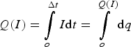 $$Q\lpar I\rpar =\vint\limits_o^{\Delta t} {I{\rm d}t=\vint\limits_o^{Q\lpar I\rpar } {{\rm d}q} }$$
at a constant I = dq/dt
Stored energy density at a constant I is given as
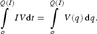 $$\vint\limits_o^{Q\lpar I\rpar } {IV{\rm d}t=\vint\limits_o^{Q\lpar I\rpar } {V\lpar q\rpar \, {\rm d}q} }.$$
The voltage V(q), where q is the state of charge, is restricted by either the difference in the electrochemical energies of the anode and the cathode or by the electrolyte energy gap between where it is reduced and where it is oxidized.
Solid insertion-compound electrodes
Insertion compounds consist of a strongly bonded host framework structure into or from which a guest working ion can be inserted or extracted reversibly over a finite solid-solution range. The interstitial space of the host framework may provide one-dimensional (1D), 2D, or 3D pathways for the guest cation as is illustrated by the three host structures of Fig. 2. The host framework is reduced on cation insertion and oxidized on extraction, and the voltage of an insertion-compound cathode versus a metallic anode is determined by the energy of the operative redox reaction in the host versus the redox energy of the anode (Fig. 3). Traditional aqueous batteries use protons as a working ion in cathodes, e.g., NiOOH, MnO2, and PbO2 with a KOH or H2SO4 electrolyte; they may also use a metal hydride as an insertion-compound anode. For a stable shelf life, the redox energies of the two electrodes must lie within the energy gap E g = LUMO − HOMO of the electrolyte (LUMO and HOMO refer, respectively, to lowest unoccupied molecular orbitals and highest occupied molecular orbitals), which restricts the voltage of a stable rechargeable battery with an aqueous electrolyte to a voltage V≲1.5 V if a kinetic barrier to ionic transfer across the electrode/electrolyte interfaces is included.[Reference Goodenough and Kim2]
Crystal structures of (a) layered LiCoO2, (b) spinel LiMn2O4, and (c) olivine LiFePO4.
Redox energies of various insertion-compound and conversion-reaction electrodes in reference to the redox energy of Li/Li+.
The initial Li-ion battery used the layered insertion compound Li1−xCoO2 as the cathode[Reference Mizushima, Jones, Wiseman and Goodenough3] and graphite, LixC6, as the anode[Reference Basu4, Reference Yazami and Touzain5] with an organic liquid-carbonate electrolyte; it was assembled in the discharged state to avoid the presence of a metallic Li0 anode.[Reference Yoshin, Sanechika and Nakjima6] A cell of this battery is illustrated in Fig. 4. The organic electrolyte has an E g = LUMO − HOMO window of 1.0 < V < 4.3 V versus Li0, and ethylene carbonate (EC) is added to the electrolyte to form an Li+-permeable passivating SEI layer on the anode (Fig. 5). However, plating of Li0 into a passivated lithium anode is not uniform; Li dendrites form that can grow across the electrolyte and short-circuit a cell with incendiary consequences. The graphite-electrode redox energy lies only about 0.2 eV below the redox energy of Li0, so an SEI layer forms on graphite also, but dendrites are not formed on Li insertion into graphite if the charging rate is not so fast that Li0 is plated on the graphite more quickly than the Li+ ions are inserted across the SEI layer into the graphite. This problem has restricted the rate of recharge of an Li-ion battery that uses a graphite anode. Nevertheless, the rate of discharge can be fast, and a stable graphite–Li1−xCoO2 cell with a voltage V ≈ 4 V has enabled a volumetric and specific energy density high enough for powering hand-held electronic devices.
A lithium-ion cell with LixC6 anode and Li1−xCoO2 cathode.
Schematic representation of the redox energies of the LixC6 anode and Li1−xCoO2 cathode in relation to the highest occupied molecular orbital (HOMO) and lowest unoccupied molecular orbital (LUMO) of the electrolyte in a lithium-ion cell.
The [M2]O4 framework of the spinel structure, Fig. 2, has a 3D interstitial space of empty tetrahedral sites bridged by empty face-sharing octahedral sites, and the Li+ mobility in this interstitial space of close-packed oxide-ions is high.[Reference Thackeray, David, Bruce and Goodenough7] However, Lix[M2]O4 spinels exhibited a decrease in voltage of 1.0 V in crossing the Li-occupation range of 0 < x < 1 to 1 < x < 2 as a result of a cooperative Li shift at x = 1 from tetrahedral to octahedral sites; this shift limits the practical capacity of a spinel electrode to an Li/M ratio of ½ as against a potential limiting ratio Li/M = 1.0 in the layered LiMO2 electrodes. On the other hand, the practical Li1−xCoO2 cathode is also limited to an Li/Co ≈ ½ because of O2 evolution for x > 0.55 as a result of the overlap of the Co3+/Co4+:3d band with the top of the O2−:2p band.[Reference Chebiam, Kannan, Prado and Manthiram8, Reference Venkatraman, Shin and Manthiram9] Nevertheless, an Li/M = 1.0 can be achieved by lowering the energy of the O2−:2p band relative to the operative redox energy as in Li[Mn1.5Ni0.5]O4 with Mn4+ and Ni2+ where the voltage varies with a negligible step on traversing from the Ni2+/Ni3+ to the Ni3+/Ni4+ redox energies as a result of pinning of these redox energies at the top of the O2−:2p band.[Reference Zhong, Bonakdarpour, Zhang, Gao and Dahn10–Reference Manthiram, Chemelewski and Lee12]
The Li4Ti5O12 = Li[Li1/3Ti5/3]O4 spinel anode does not require formation of an SEI layer that robs Li+ from a discharged cathode on the initial charge, but the voltage is reduced by over 1.2 V, which reduces the energy density with a given cathode.[Reference Ferg, Gummoow, de Kock and Thackeray13] Nevertheless, this spinel has been used as the anode with an olivine Li1−xFePO4 cathode in a large stationary battery in Northern Quebec for EES of electricity generated by a wind farm. It is also being used as an anode in some EV batteries.
Manipulation of the energy of the redox couple by a counter cation is illustrated by the olivine structure LiMPO4 of Fig. 2. The strong covalent bonding in the (PO4)3− polyanion makes it acidic, which lowers the covalent contribution to the M–O bond, thereby lowering the energy of the M2+/M3+:3d redox couple.[Reference Manthiram and Goodenough14, Reference Padhi, Nanjundaswamy and Goodenough15] Moreover, it also stabilizes the O2−:2p energy, which allows oxidation of LiNiPO4 at over 5 V, which means withdrawal of Li from LiNiPO4 oxidizes the liquid-carbonate electrolyte. With a V ≈ 4.1 V for the Mn2+/Mn3+ couple of LiMnPO4, which would be well-matched to the E g window of the electrolyte, a cooperative orbital ordering on the octahedral-site high-spin Mn3+ creates a problem for LiMnPO4 as a cathode. Moreover, the particles are platelets and the 1D Li+ conductive channels are oriented perpendicular to the plane of the platelets in LixFePO4, but within the platelets in the other olivines.[Reference Dong, Wang, Zhang, Zhao, Zhou, Xie and Goodenough16]
These examples illustrate the constraints on batteries using insertion compounds as the electrodes of a rechargeable battery even where suitable electrolytes with larger E g windows are identified. The energy density of rechargeable Li-ion batteries based on an insertion-cathode strategy may be incrementally improved for powering a hand-held electronic device, but the cost will haunt efforts to power a PHEV or small EV; an alternative strategy must be developed for large-scale, low-cost EES in rechargeable batteries. At the present time, strategies involving insertion-compound cathodes include development of Li-alloy anodes[Reference Obrovac and Christensen17–Reference Park, Kim, Kim and Sohn19] that allow larger capacities and faster charging without too large a compromise of voltage, electrolytes with a larger window, insertion-compound cathodes with a capacity exceeding an Li/M = ½ ratio,[Reference Lu, Chen and Dahn20, Reference Armstrong, Holzapfel, Novák, Johnson, Kang, Thackeray and Bruce21] and the use of nanosized, high-voltage insertion-compound cathodes assembled in a stable, elastic, conductive matrix to connect the particles electronically to one another and the current collector. Whether this approach can achieve the cost reduction, cycle life, and power density needed to compete with the internal combustion engine can be expected to challenge the research community for the next 10 years. Alternative applications will keep the effort viable.
On the other hand, the much greater availability and lower cost of Na compared with Li is prompting development of Na-ion batteries for low-cost grid EES based on the same basic strategies. The redox energy of Na0 is 0.3 eV lower than that of Li0, and host cathode structures for a Na+ guest must have a larger interstitial space than can be realized in a close-packed oxide or sulfide anion array other than in a layered compound that allows the distance between layers to expand. As a result, layered hosts are commonly being investigated for Na-ion batteries.[Reference Carlier, Cheng, Berthelot, Guignard, Yoncheva, Stoyanova, Hwang and Delmas22] A larger interstitial space can also be created using polyanions such as (PO4)3− and (SO4)2− as host anions, which may lower only slightly the volumetric density without compromising cost. An example is the hexagonal Fe2(SO4)3 framework illustrated in Fig. 6, of the Na+ solid electrolyte Na1+3xZr2(P1−xSixO4)3,[Reference Goodenough, Hong and Kafalas23] which is referred to as NASICON. As an electrode, the Zr is replaced by a first-row transition element such as V4+.[Reference Gopalakrishinan and Rangan24, Reference Gover, Bryan, Burns and Barker25] This framework can accommodate Li+ as well as Na+ guest ions with 0 < x < 1 for fast guest-ion transport. However, the most economical and smallest Na+-ion framework appears to be that of the Prussian-blue cyanides prepared at room temperature with the cubic or rhombohedral ReO3 structure of Fig. 7(a): a dried FeMn(CN)6 host, for example, can accommodate two Na+ ions per formula unit into the large body-centered site with essentially no voltage step between operation on the low-spin Fe2+/Fe3+ and high-spin Mn2+/Mn3+ couples on reversible insertion/extraction of Na+ at a flat 3.5 V versus Na0 [Fig. 7(b)].[Reference Song, Wang, Yu, Liu, Guo, Xiao, Lee, Yang, Henkelman and Goodenough26] This cathode Na+ insertion compound now needs a good, low-cost anode and a demonstration of a long cycle life.
Crystal structure of the NASICON Na1+3xZr2(P1−xSixO4)3 structure.
(a) Local structure of rhombohedral Na1.89Mn[Fe(CN)6]0.97, showing the Na+ displacements and distorted framework and (b) galvanostatic initial charge–discharge profiles of Na1.89Mn[Fe(CN)6]0.97 at 0.1C (15 mA/g) rate.
Solid conversion-reaction electrodes
The limitations of the capacities of insertion-compound electrodes have created interest in conversion-reaction electrodes, which do not maintain their initial structure during discharge/charge. Sulfur with a two-electron redox reaction per atom offers an order of magnitude higher theoretical capacity (1672 mAg/g) than the currently used insertion-compound cathodes (<200 mAh/g) both with lithium and sodium anodes. Sulfur is also abundant and environmentally benign. However, the sulfur cathode suffers from low electrochemical utilization and poor cycle life arising from the insulating nature of both S and the discharge product Li2S or Na2S and the shuttling of dissolved polysulfide species between the cathode and anode during cycling.[Reference Rauh, Abraham, Pearson, Surprenant and Brummer27–Reference Bruce, Freunberger, Hardwick and Tarascon29] Enormous progress with capacities of ~1400 mAh/g and long static and dynamic life has been made during the past 5 years to overcome these problems by employing sulfur–carbon or sulfur–conductive polymer nanocomposites or novel cell designs with a carbon-paper interlayer between the sulfur cathode and the separator or carbon-coated conventional separators (Fig. 8).[Reference Ji, Lee and Nazar28–Reference Manthiram, Fu, Chung, Zu and Su31] However, the deposition of sulfur species on the Li or Na metal anode by any trace amount of migrating polysulfides and the safety issues with the Li and Na anodes need to be fully solved to have the ambient temperature Li–S or Na–S batteries commercially viable.
(a) Cell configuration and (b) cycle life and Coulombic efficiency of a lithium–sulfur cell with a carbon-coated separator.
With the conversion-reaction anodes, elemental solids[Reference Obrovac and Christensen17–Reference Park, Kim, Kim and Sohn19] such as Si, Sn, and Sb, and transition-metal oxides MOx (M = Fe, Co, or Ni)[Reference Taberna, Mitra, Poizot, Simon and Tarascon32, Reference Poizot, Laruelle, Grugeon, Dupont and Tarascon33] have become appealing due to their high capacities. The fast capacity fade encountered due to large volume changes (>100%) with the elemental solids has been overcome by adopting nanocomposite or innovative synthesis approaches, but at the expense of volumetric capacities.[Reference Chan, Peng, Liu, McIlwrath, Zhang, Huggins and Cui34, Reference Tu, Zhao, Hu, Jiao, Hou and Zhu35] Also, they suffer from large irreversible capacity loss in the first cycle as a result of the high surface area of the small anode particles. Among the elemental-solid anodes, Sb with a flat charge/discharge voltage of ~0.8 V versus Li0 or ~0.5 V versus Na0 offers the advantage of fast charge and better safety as dendrite growth can be prevented[Reference Yoon and Manthiram36] With the MOx oxide insertion anodes, on the other hand, the higher operating voltages (>1 V) and the hysteresis with a large difference between the charge and discharge voltages pose difficulties.[Reference Poizot, Laruelle, Grugeon, Dupont and Tarascon33, Reference Muraliganth, Vadivel Murugan and Manthiram37, Reference Zhong, Xia, Zhang, Li, Wang and Chen38]
The SEI layer that forms on an anode not only robs Li+ or Na+ from the cathode to give an irreversible capacity loss on a first charge; its composition at the interface with the anode also changes on cycling to limit the cycle life of a cell. Improving the anode of a rechargeable Li-ion or Na-ion battery with an alternative strategy can be expected to be an ongoing research topic for the next decade. One approach will be to find a means to avoid dendrite formation on a metallic Li0 and/or Na0 anode by interfacing it with an electrolyte having a high-energy LUMO; another approach will be to stabilize the SEI–layer interface with the anode while minimizing the irreversible capacity loss of the cathode on the initial charge of a cell.
Liquid electrodes
Cells containing liquid electrodes are of two types: (i) molten electrodes with either a solid or an immiscible liquid as electrolyte and separator; (ii) a soluble redox molecule in a flow-through cell in which the liquid electrode is cycled to/from an external storage tank. Both approaches have the potential advantage of high capacity at low fabrication cost. However, batteries with molten electrodes have the disadvantage of operating at high temperatures, and room-temperature redox flow-through electrolytes require a solid-electrolyte separator that prevents crossover of the soluble redox molecules.
‘Molten electrodes with a solid electrolyte’ have been developed for the Na/S battery, which operates at 350 °C. One prototype, large-capacity Na/S battery has been installed in Japan for EES for the grid. The cells of this battery have a molten-sodium anode in an open ceramic Na+-electrolyte container that sits in a molten sulfur cathode impregnating a carbon felt attached to a metallic current-collector outer container to supply electrons for the Na–S reaction. The β,β“-alumina Na+ electrolyte consists of insulating spinel blocks separated by an Na2−xO layer providing 2D Na+ transport.[Reference Kummer, Sudworth and Tilley39] Thermal cycling and management is a cost, and high-temperature chemical stability of components presents an additional maintenance cost. Also, Na/NiCl2 (zebra) batteries are being manufactured for stationary EES, particularly by General Electric and by FIAMM in Europe.[Reference Sudworth40]
‘Molten electrodes with an immiscible-liquid electrolyte’ is a concept presently being developed at MIT; the battery cell consists of a molten-lithium anode sitting on a 20:50:30 LiF–LiCl–LiI molten-salt electrolyte that sits, in turn, on a liquid Sb–Pb near eutectic composition in which the Li reacts with the Sb to LixSb (x < 3) at a discharge voltage V ≈ 0.8 V.[Reference Yoon and Manthiram36] This cell operates at 450 °C, but it appears to offer a low-cost fabrication and cell assembly. Whether this strategy can stimulate a similar approach that offers a lower operating temperature and a higher discharge voltage remains to be seen.
‘Redox flow-through electrodes’ have been tested in aqueous batteries with a V4+/V3+ anode redox molecule and a V5+/V4+ cathode redox molecule.[Reference Skyllas-kazacos and Grossmith41, Reference Kim, Yan, Schwenzer, Zhang, Li, Liu, Yang and Hickner42] These cells offer a low voltage and the NAFION separator membrane used leaks redox species across it. However, these cells have demonstrated the feasibility of the flow-through concept in which the redox molecules exchange electrons at an electronically conducting carbon mesh attached to a current-collector and store electrical energy in an external tank. Higher voltages can be achieved with organic liquids and only a liquid flow-through cathode, but realization of the concept will depend on development of a suitable solid Li+- or Na+-electrolyte separator to block crossover of the soluble redox molecule.
Gaseous electrodes
Reversible gaseous cathodes operate on air at room temperature in a metal–air battery[Reference Abraham and Jiang43–Reference Girishkumar, McCloskey, Luntz, Swanson and Wilcke45] and at intermediate temperatures in a reversible solid oxide fuel cell (RSOFC).[Reference Xu, Li, Zhao, Goodenough and Huang46] In both cases, the critical cathode material must provide a low-cost, chemically stable, active catalyst for the oxygen-reduction and oxygen-evolution reactions (ORR and OER). The anode of the solid oxide fuel cell (SOFC) is also gaseous; it operates on H2 released from the H2O of the exhaust gas as it oxidizes the metal of an external chemical bed. A conventional metallic-nickel configuration provides the catalyst for the anode. Mixed oxide-ion/electron conductors need to be optimized for the cathode catalysts. A near-term research goal will be development of the oxide catalysts for the intermediate-temperature (500 °C) reversible fuel cells; proof of this concept has been demonstrated by the high-temperature fuel-cell battery illustrated in Fig. 9.
A reversible solid oxide fuel cell (RSOFC) with a chemical storage bed composed of Fe–FeOx.
Development of catalysts for a metal–air battery operating with an organic rather than aqueous electrolyte is a challenge that will continue to be actively researched. In addition, catalysts for reforming natural gas to liquid or of producing the H2 from water at T < 500 °C in an RSOFC is also being pursued.
Electrolytes and separators
A high-energy-density rechargeable cell requires a large V(q)Q(I) product (Eq. 5). For a given cathode strategy, the highest energy densities would be given by a metallic lithium or sodium anode, Li0 or Na0. Although all-solid-state lithium batteries with a solid Li+ electrolyte having the bottom of its conduction band above the redox energy of Li0 have been made, retention of a good working-ion contact across the electrode/electrolyte interfaces can only be retained at present with electrodes that do not have too large a volume change with the insertion/extraction of the working guest cation. A liquid electrolyte having its LUMO above the redox energy of Li0 is to be preferred. Considerable attention has, therefore, been given to ionic liquids, which are non-flammable; but they are too viscous to provide a high-enough Li+ or Na+ conductivity at room temperature. Other Li+ or Na+ electrolytes that are molten at acceptable operating temperatures have yet to be explored.
Once an electrolyte that allows use of an Li0 or Na0 solid anode of high capacity Q(I) at a rate of full charge and discharge greater than 6C (10 min) has been identified, the next problem will be to improve the capacity of the cathode beyond what is possible with an insertion compound. In order to use a liquid flow-through cathode, it will be necessary to develop a low-cost, thin, mechanically robust and, preferable, flexible solid Li+-, or Na+-electrolyte separator; the separator must block the soluble redox molecules of the liquid cathode from crossing over to the anode. Low-cost composite porous polymers saturated with a liquid electrolyte have been made with the desired mechanical properties and can block larger redox molecules from crossover, balancing the concentrations of soluble species in the anolyte with redox molecules of the catholyte on the opposite side of the membrane can prevent osmosis from drying out the anolyte. However, with a variable concentration of soluble species in the catholyte of an Li/S cell on charge and discharge, an all-solid electrolyte separator will be needed to prevent osmosis from limiting the cycle life of an Li/S cell.
Conceptually, the alternative cathode giving the highest low-cost energy density would be a gaseous air cathode. A reversible air cathode requires good catalysts for both the ORR and OER. Low-cost oxide or carbon catalysts have been identified for an alkaline aqueous catholyte, but not quite for a non-aqueous electrolyte.[Reference Maiyalagan, Jarvis, Therese, Ferreira and Manthiram47, Reference Li, Cai, Dai and Manthiram48] To achieve a high-voltage Li/air or Na/air cell, it appears necessary to develop a dual-electrolyte (also called hybrid) cell in which a solid-electrolyte separator is stable in a non-aqueous anolyte on one side and alkaline or acidic aqueous catholyte on the other side.[Reference Visco, Nimon and Katz49, Reference Manthiram and Li50] The challenge for future research will be to develop the solid-electrolyte separator with the necessary mechanical strength to be used as a large-area, low-cost film separating the anode and cathode compartments. In the absence of a suitable solid-electrolyte separator, catalysts for a reversible air electrode in an aprotic liquid will be needed.
The RSOFC concept, which uses gaseous anodes and cathodes with a solid oxide electrolyte, also needs the identification of low-cost catalysts for the ORR and OER; catalysts reforming methane to a liquid fuel and the production of H2 from water also need to be identified.
Conclusions
Rechargeable batteries are the most viable option for efficiently storing and utilizing electricity generated from wind, solar, or nuclear energies as well as for EVs. As we go from portable electronic devices to EVs to grid storage, the order of priority of the performance parameters among energy, power, cycle life, cost, safety and environmental impact changes, requiring the design and development of new materials and battery chemistries. This perspective provides an overview of various possible approaches. However, competition with fossil fuels is a daunting challenge for large-scale applications, and intuitive design and development of new materials and battery chemistries/configurations are needed.
Acknowledgments
This work was supported by the US Department of Energy, Office of Basic Energy Sciences, Division of Materials Sciences and Engineering under award number DE-SC0005397. The authors thank Dr. Longjun Li for his assistance with the figures.



