I. INTRODUCTION
In recent years, nanofabrication technology has enabled the development of small aerospace aircraft of reduced size and improved performance when compared with conventional aircraft. New small unmanned air vehicles, designated as micro air vehicles (MAVs), are increasingly attractive for use in the scientific, the government, the commercial researches, and military purposes. A typical length dimension and gross takeoff weight of MAV, respectively, are <150 mm and approximately 200 g [Reference Pines and Bohorquez1]. For example, 10 cm cord length and 14 m/s cruising speed were achieved by a small unmanned air vehicle called the Black Widow (AeroVironment Inc., Monrovia, CA, USA) [Reference Grasmeyer and Keennon2]. Although MAV research and development are aimed primarily at military applications, MAVs are anticipated for use in the various fields such as the environmental observation, information gathering during and after disasters, disaster monitoring, and investigation under dangerous conditions. However, the MAV design and performance still entail many difficulties related to aerodynamics and flight endurance. Because of their small size and flight speed compared with the normal aircraft, the flow field around the MAVs becomes a low-Reynolds number. For example, the Reynolds number for the passenger airplane and the MAVs are, respectively, 107–108 and 104–105. Low-Reynolds number aerodynamics have been investigated in attempts to develop MAVs using bio-inspired flight of animals such as birds, bats, and insects [Reference Shyy3]. Furthermore, the flight duration is an especially severe problem for MAVs. Because a typical MAV can fly for only about 15 min using currently available batteries, wireless power transfer (WPT) technology supports increased possibilities and benefits of MAVs.
To date, WPT via radiowaves have been demonstrated to support flight objects [Reference Matsumoto4–Reference Fujino6]. Especially, WPT via magnetic resonance coupling has attracted great interest for use in near-field MAV applications. Griffin experimentally demonstrated a prototype WPT system of magnetic resonance coupling by using a small unmanned air vehicles to transfer nearly 5 W of power to a ground sensor [Reference Griffin and Detweiler7]. Campi et al. investigated the magnetic field levels and associated electromagnetic compatibility problems relatively to the presence of metallic objects such as drone frame and engines [Reference Campi, Dionisi, Cruciani, De Santis, Feliziani and Maradei8]. In our previous study, to demonstrate WPT using magnetic resonance coupling to an object moving in three-dimensional (3D) space, the transmission efficiency of an electrically powered miniature helicopter was optimized by automatic impedance matching for different flight attitudes: a maximum flight altitude of 590 mm was achieved [Reference Yamakawa, Shimamura, Komurasaki and Koizumi9].
In contrast, little attention has been devoted to application of microwave power transmission for far-field MAV application. Vitale primarily developed a 1.3 GHz microwave power transmission system with a single main rotor MAV [Reference Vitale10]. The receiving system was demonstrated to operate at two frequencies, 1.0 and 1.3 GHz with <2 W of transmitted power. Kim et al. developed a polarization-free flexible rectenna array for MAVs application using a polyimide film [Reference Kim, Yang, Song, Jones, Elliott and Choi11]. They obtained 0.44 W power output with the maximum efficiency of 29%. Suzuki et al. also developed a flexible rectenna with a circular patch antenna using the polyimide film [Reference Suzuki, Iida, Niki, Tanaka, Hashimoto and Sasaki12]. At the University of Tokyo, the “Innovative Aerial Robot Project” particularly addressing unmanned/micro aerial vehicles is being conducted as part of the Japanese 21st century COE program. A 5.8 GHz microwave power transmission to MAVs with a 2.45 GHz software retrodirective system has been studied in this project [Reference Komurasaki, Nakagawa, Ohmura and Arakawa13–Reference Nako, Okuda, Miyashiro, Komurasaki and Koizumi15]. These studies preliminarily demonstrated the possibility of WPT for MAVs by the development of rectenna. However, a microwave power transmission system for MAVs requires a comprehensive system design that includes MAV requirements for the WPT design, rectenna development, beam forming technology, a position tracking system, and overall system evaluation.
As described in this paper, we comprehensively evaluated microwave power transmission feasibility for MAVs. In Section II, the requirement specifications of MAV design were evaluated. A microwave power receiving system using a felt rectenna was proposed for a moving MAV to install a flexible and lightweight rectenna on the MAV surface. Section III of this paper specifically addresses the design of a textile-based rectenna. A 5.8 GHz left-hand circular-polarized microstrip patch antenna was developed on the felt substrate. A rectification circuit was formed on the back side felt while sandwiching a copper foil as a ground plate. Section III explains the bending effect on the textile-based rectenna performance. The bending test of antenna performance and RF–DC conversion efficiency were applied separately. Section IV presents a wireless power transmission demonstration with a small airplane. A MAV with the 2.45 GHz retrodirective system was developed for position tracking. Multiple rectennas were connected in parallel and were loaded on the back-surface of the MAV. The average and maximum received power of the multiple rectennas on the MAV surface were measured as a function of the turning flight angle. In Section V, this study investigated the feasibility of the microwave power transmission for MAVs using the textile-based rectenna and the conventional rectenna.
II. MAV DESIGN REQUIREMENTS FOR WPT SYSTEM
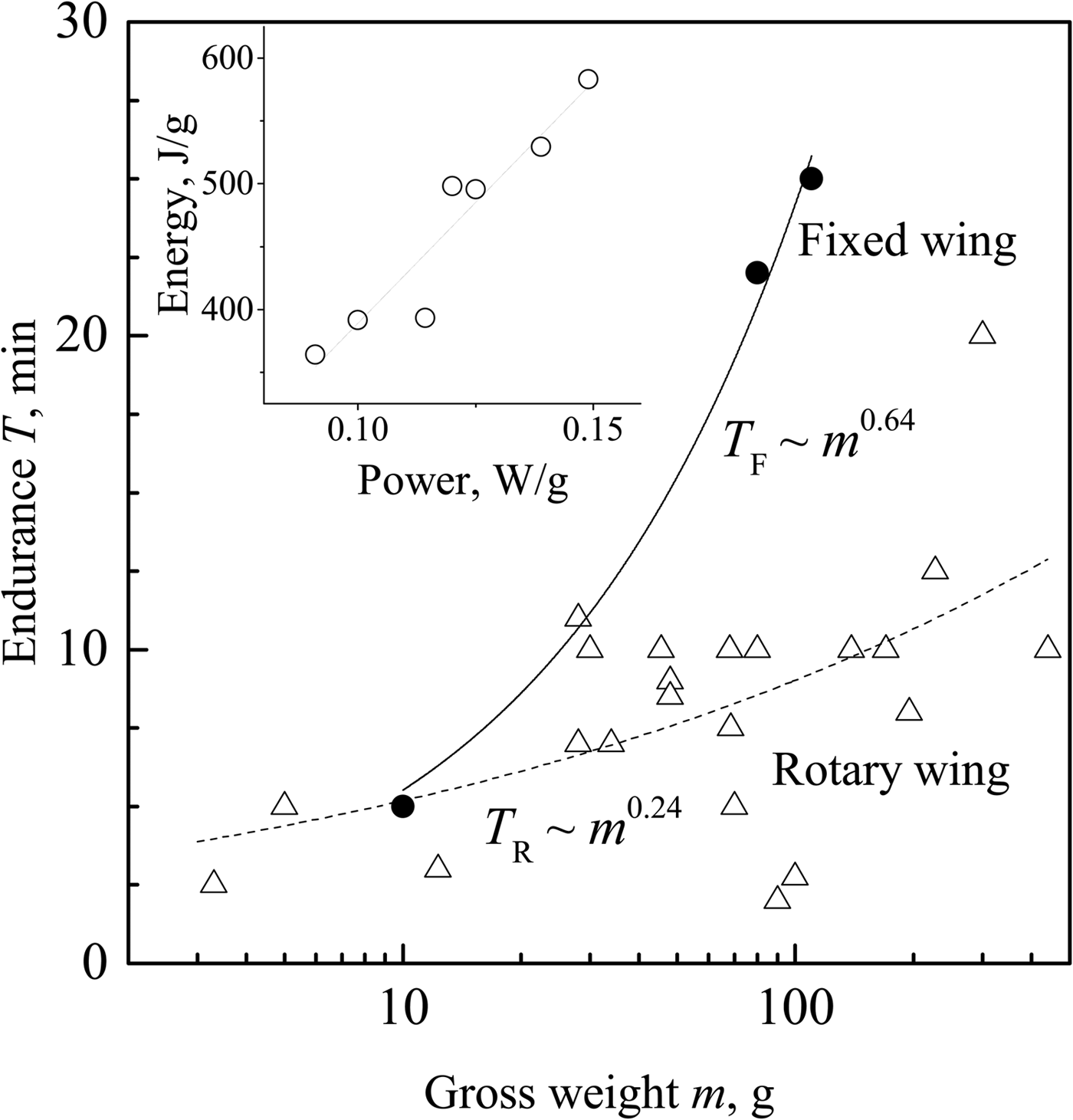
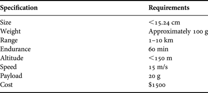
To design the microwave power transmission system, the specific requirements for MAVs are necessary. Types of MAVs consist of fixed wings, rotary wings, and flapping wings. Energy and power requirements of the three flight modes have been investigated in earlier studies such as those of Mukherjee et al. [Reference Mukherjee, Heiges and Matthies16] and Woods et al. [Reference Woods, Henderson and Lock17]. Table 1 presents specifications and requirements for MAVs [Reference Pines and Bohorquez1]. To consider the microwave power transmission attempts to the MAVs, the size, weight, and altitude must be regarded. The operational range of MAV is of some importance in this case if multiple microwave sources on the ground can be presumed. The operational ceiling altitude depends on the microwave source power and the antenna performance of the transmitter and receiver. This topic is discussed in a later section. The relation between the gross weight of MAVs and the endurance is presented in Fig. 1. Specifications of MAVs were obtained from earlier reports [Reference Pines and Bohorquez1, Reference Mukherjee, Heiges and Matthies16]. The endurance of MAVs for the rotary wing and the fixed wing are expressed, respectively, as TF ~ m 0.64 and TR ~ m 0.24. According to Table 1, it is difficult to achieve 60 min endurance using a conventional battery because the typical endurance of MAVs is <15 min. Typical lithium-ion batteries for micro autonomous systems have weight of 1–5 g, power capacity of 2–10 W, and energy capacity of 500–3000 J [Reference Mukherjee, Heiges and Matthies16]. As presented in Fig. 1, the conventional battery performance is in the range of 0.1–0.5 W/g and 400–600 J/g.
Relation between the gross weight of MAVs and endurance with low battery performance [Reference Pines and Bohorquez1, Reference Mukherjee, Heiges and Matthies16].

MAV design specification and requirements [Reference Pines and Bohorquez1].

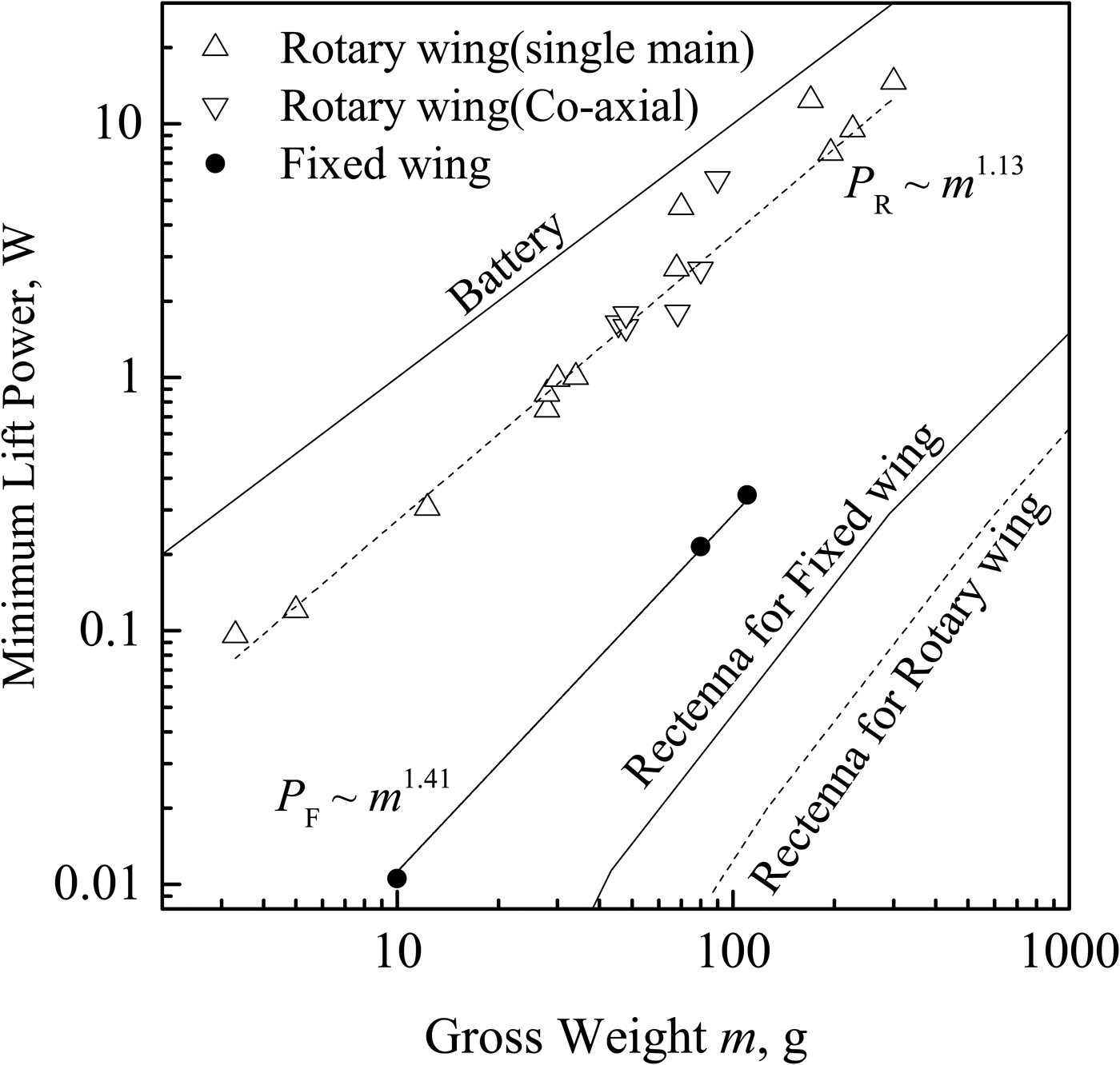
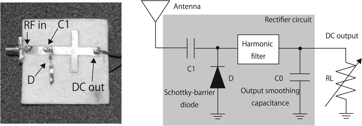
Although the microwave power transmission enables disengagement of the limit of MAV endurance, the rectenna weight for required power presents severe difficulties. Figure 2 shows the minimum lift power for rotary wing type and the fixed wing type MAVs in terms of gross weight. The power requirements for the fixed wing are expressed as described in an earlier report [Reference Anderson18]:
 $$P = WV\left( {\displaystyle{{C_L} \over {C_D}}} \right)^{ - 1}.$$
For that equation, weight W (=mg) [N] and cruising speed V were obtained from an earlier report [Reference Pines and Bohorquez1]. In Fig. 2, PF and PR , respectively, represent the minimum lift power as the function of gross weight for the fixed and rotary wing types. CL and CD , respectively, represent the lift and drag coefficients. These coefficients are an airfoil characteristic ratio as a function of airfoil shapes and Reynolds number. For low-Reynolds number flyers, CL /CD is typically 5 [Reference Lissaman19]. For rotary wing and flapping wing devices, the required power for the hovering flight is obtained as shown below [Reference Woods, Henderson and Lock17].
 $$P = W\sqrt {\displaystyle{W \over {\left( {2\rho S} \right)}}}. $$
In that equation, ρ and S, respectively, denote the ambient gas density and the wing area. The hovering efficiency of rotary wing was assumed at unity [Reference Pines and Bohorquez1]. The total weight of rectenna system consists of the antenna WAntenna and the number of rectifier as
 $$\eqalign{W_{Rectenna} & = W_{Antenna} + N_{Rectfier}W_{Rectifier} \cr & \quad = \sigma S + \displaystyle{P \over {P_{break}}}W_{Rectifier},}$$
where σ stands for the area density of the antenna material. The estimation of equation (3) removes the DC output cable, the load, and other assembly parts. The number of required rectifiers obtained from the required-flight power P is divided by the breakdown threshold of the rectifier Pbreak .
Minimum flight power for the rotary wing and fixed wing versus gross weight m as compared with the required rectenna weight.

The wing area is expressed as a function of the gross weight. According to two earlier reports of the literature [Reference Pines and Bohorquez1, Reference Mukherjee, Heiges and Matthies16], the wing areas of the rotary wing and the fixed wing are, respectively, S = 9.8 × 10⁻³m0.64 and S = 3.62 × 10⁻⁴m0.85.
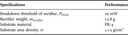
The rectifier specifications are shown in Table 2: the battery and gross weight are, respectively, 1 and 40 g for operation power of 100 mW for the fixed wing MAVs. In this case, it is difficult to apply the microwave power transmission because the total rectenna weight of 100 g is greater than the gross weight. The rotary wing MAVs present a more difficult situation. Furthermore, a flexible and lightweight substrate is necessary to install the rectenna on the MAV-curved surface and the flapping wing.
Specifications of the conventional rectifier [Reference Komatsu, Katsunaga, Ozawa, Komurasaki and Arakawa14].
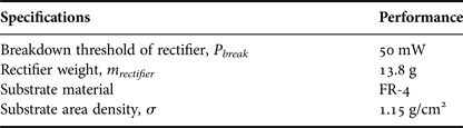
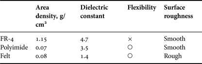
Table 3 presents specifications of flexible substrates as compared with the FR-4 substrate. In terms of light weight and flexibility, a polyimide and textile substrate is suitable for WPT applications to the MAVs because the surface area density of both substrates is much less than that of FR-4.
Specifications of flexible substrates compared with FR-4 [Reference Suzuki, Iida, Niki, Tanaka, Hashimoto and Sasaki12, Reference Komatsu, Katsunaga, Ozawa, Komurasaki and Arakawa14, Reference Tanaka24].

Furthermore, the surface roughness of airfoils affects the maximum lift-to-drag ratio (CL/CD ) max . McMasters and Henderson found that the rough airfoil performance (CL /CD ) max is much better than that of the smooth airfoil in the range of insects, birds, and MAVs operation for Reynolds number, Re < 105 [Reference Lissaman19]. This complex flow physics is beyond the scope of this report. Briefly, at lower Reynolds number, the viscous effects are large. Airfoil roughness is desirable to delay flow separation on the wing surface [Reference McMasters and Henderson20]. To date, however, little information has emerged about MAV applications using the flexible substrate; non-woven fabric substrate has been used for wireless communication and for energy harvesting of wearable applications [Reference Massey21–Reference Monti, Corchia and Tarricone26]. The bending antenna performance for different textile materials in terms of return loss, axial ratio (AR), radiation pattern, and gain has been presented and discussed [Reference Sankaralingam and Gupta27–Reference Alqadami and Jamlos30]. This study examined the textile-based rectenna for microwave wireless power transmission of MAVs. The bending tests of antenna performance and RF–DC conversion efficiency were investigated separately, as described in the following section.
III. DEVELOPMENT OF THE TEXTILE-BASED RECTENNA
A) Rectenna design
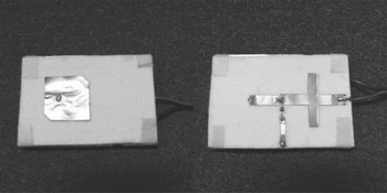
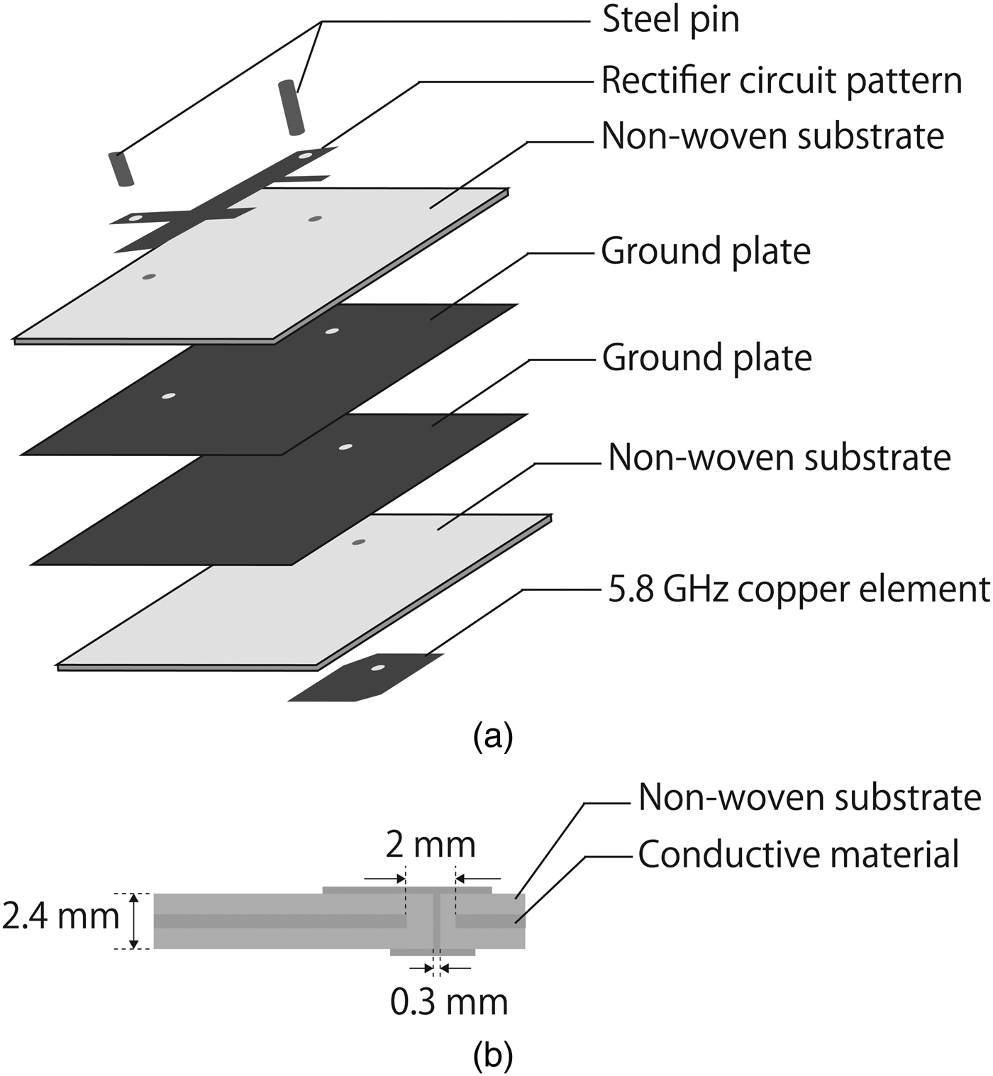
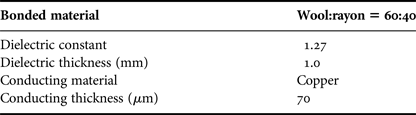
Microwave power transmission studies for mobility have used a polarity-free rectenna array such as a multiple dipole antenna type and a single polarized antenna type [Reference Shinohara31]. The salient advantages of the multiple dipole antenna are its simplicity of polarization angle design and power conversion design. However, the areal size of a single polarized patch antenna is smaller than that of multiple dipole antenna unit. For this study, a 5.8 GHz left-hand circular-polarized microstrip patch antenna was developed on the felt substrate. To install the small space of MAVs, a rectification circuit was formed on the back side felt while sandwiching a copper foil as a ground plate. A moment method electromagnetic simulator (SONNET) was used to evaluate the antenna and rectenna dimensions. The 5.8 GHz square patch antenna was designed with circular polarization by trimming opposite corners. Table 4 presents specifications of the copper foil and the substrate for the rectenna. A 60% wool and 40% rayon felt was used as the rectenna substrate. To produce this lightweight and flexible rectenna, copper foil (no. 831S; Teraoka Seisakusho Co. Ltd.) was used for the patch antenna, the microstrip line, and the ground plate. Those copper foils were cut by a board processing machine (ProtMat S62; LPKF Laser & Electronics AG Inc.). Electrically conductive acrylic adhesive was used for manually assembling the substrates and copper foil. Numerous prototypes were developed until the manually assembling error and the effect of gluing uncertainties become negligibly small. The substrate and copper foil thicknesses are, respectively, 1.0 mm and 70 µm. To develop the textile-based rectenna, the dielectric constant of the textile material used should be ascertained. Many reports of the literature have described methods to find the dielectric constant [Reference Zhang, Vulin and Pan32–Reference Haskou, Ramadan, Al-Husseini, Kasem, Kabalan and El-Hajj34]. To simplify analysis of the dielectric constant of the felt material, the cavity model of the square patch antenna with the TE100 mode was used [Reference James, Hall and Wood35, Reference Carver36]. Results show that the dielectric constant was estimated as 1.27. Figure 3 portrays the microstrip patch antenna (left side) and the rectifier circuit (right side). The total size and weight of the antenna were, respectively, 45 mm × 65 mm and 1.6 g. Figure 4 presents a breakdown view and the cross-section of the rectenna at the feeding point. The ground copper plate was inserted into a non-woven fabric dielectric. The total rectenna thickness was 2.4 mm. As presented in Fig. 4(a), from the top, the first layer represents the rectifier circuit element. The second is the non-woven fabric substrate. The third and fourth are the ground plates. The fifth is the non-woven fabric substrate. The sixth is the 5.8 GHz antenna element. A via-through exists between the two active copper layers, the two ground plates, and the two substrates. Because the antenna and rectifier were developed and evaluated separately, two ground plates are necessary for the rectenna. The respective diameters of the conductive wire and the through hole on the conductive material were 0.3 and 2 mm fixed with tin solder. Furthermore, a via-through between the rectenna pattern, the substrate and the ground plate was mounted for the ground connection.
Lightweight flexible rectenna: the microstrip patch antenna (left side) and the rectifier circuit (right side) were developed on a 45 × 65 mm felt substrate.

(a) Breakdown and (b) cross-sectional view of the lightweight flexible rectenna.

Specifications of the textile and conductive material.

B) Receiving antenna design and measurement in a bending condition
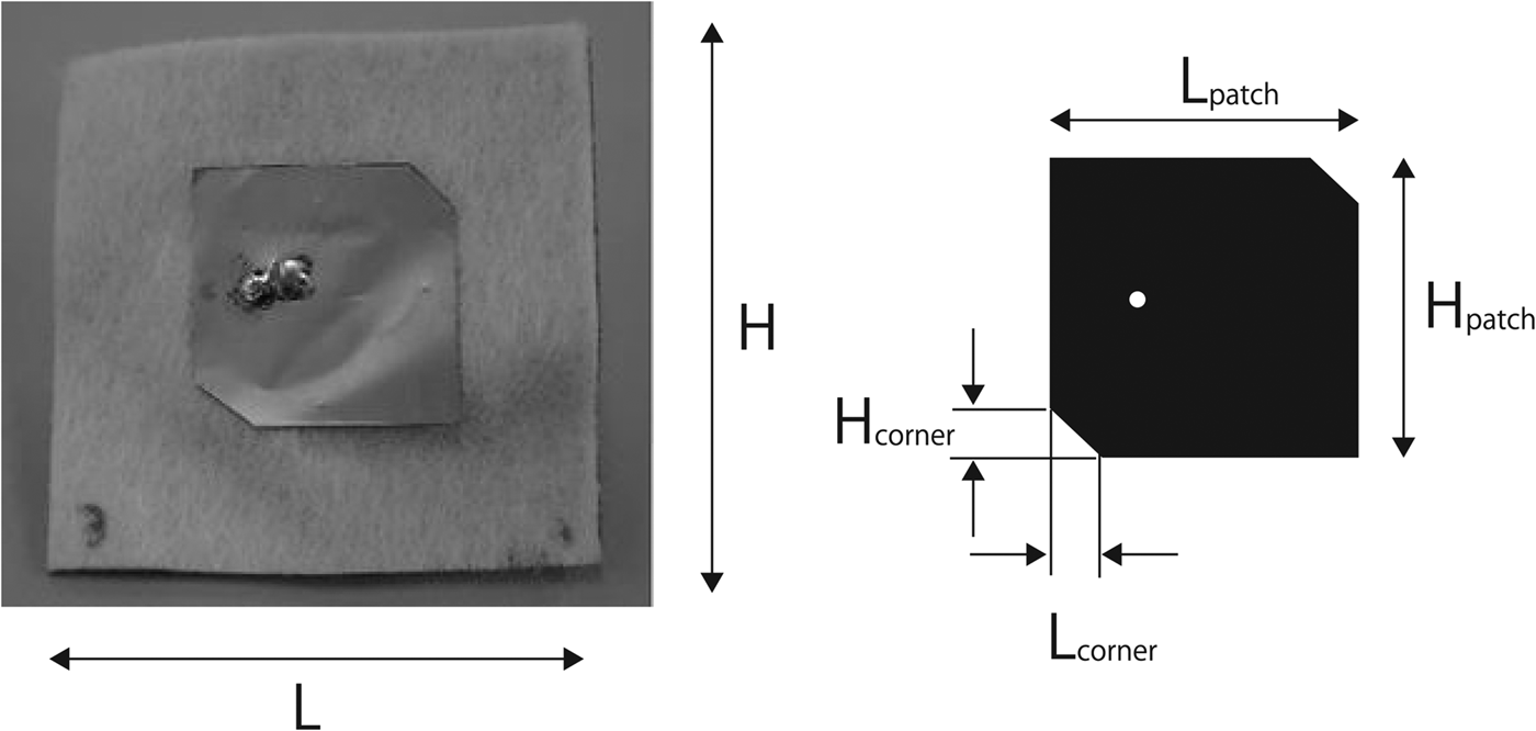
To elucidate the return loss of the circular-polarized microstrip patch antenna under a bent condition, a 5.8 GHz left-hand circular-polarized microstrip patch antenna was developed as depicted in Fig. 5. The patch antenna dimensions are fundamentally the same as those presented in Fig. 5, except for the substrate size. The rectangular element has side length of 21.7 mm with equilateral triangles trimmed from the rectangle. The antenna gain in the normal condition was 6.3 dBi.
A 5.8 GHz circular polarized wave antenna (right) and the antenna size (left): H = L = 43.9 mm, Hpatch = Lpatch = 21.7 mm, Hcorner = Lcorner = 3 mm.

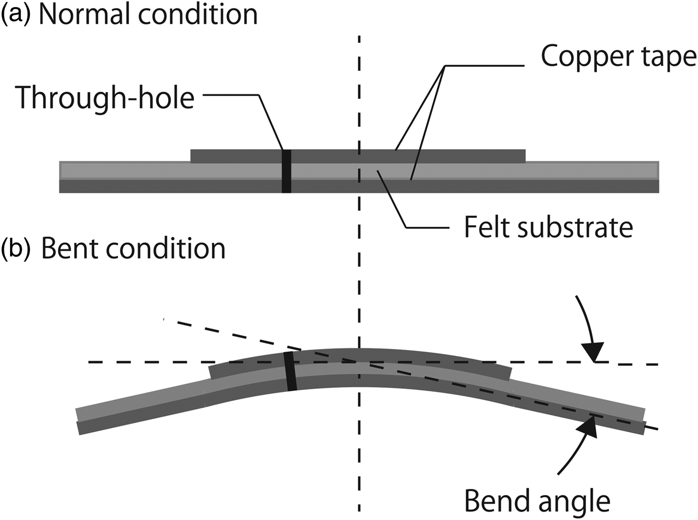
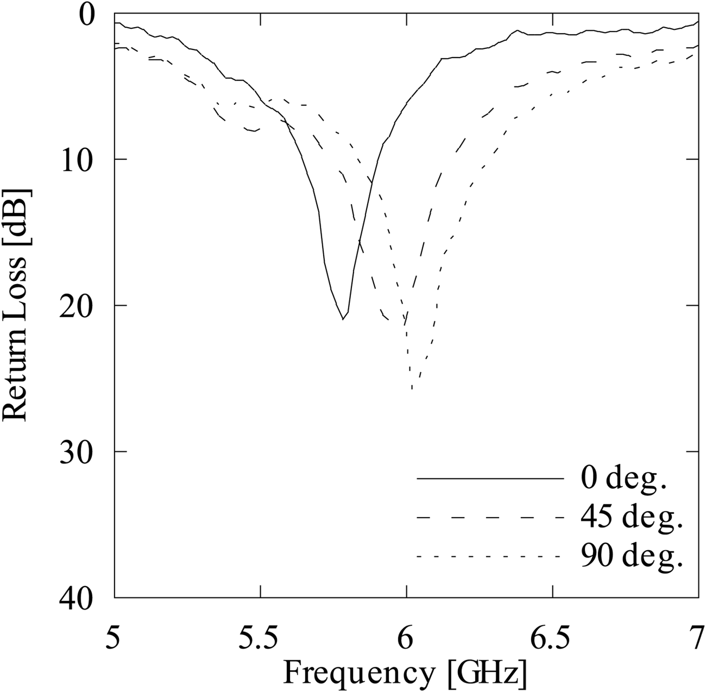
To evaluate the bending effect for the antenna properties, as depicted in Fig. 6, it was folded in half. The bending angle was defined. As the high electrical insulation with low dielectric constant, a polystyrene form with a slit was used to hold the bending antenna. Although the precision of the bending angle depends on the fabrication error of the slit on the polystyrene form, the minimal variation of the bending angle slightly affects the antenna performance. Figure 7 presents the return loss of the antenna under each bent condition, as evaluated using a vector network analyzer (8722D; Agilent Technologies Inc.).
Bend angle of the microstrip patch antenna.

Return loss of the lightweight flexible antenna in a bent condition.

Results show that the antenna return loss RL in the normal condition was 20.3 dB. From Fig. 7, the resonance frequency of antenna was shifted to the higher frequency by 0.25 GHz for each 45° of bending angle. With increase of the bending angle, the antenna aperture and the resonance length were reduced as presented in Fig. 7. Therefore, the resonance frequency was shifted upward [Reference Salonen and Samii29]. The return loss of microstrip patch antenna was increased with the bending angle RL = 12.3 dB at 45°. RL at 45° was 5% less than under normal conditions. However, the microstrip patch antenna under a 45° bent condition satisfied the low-loss reflection antenna condition.
To investigate the circular polarization of the microstrip patch antenna, the AR was measured using a microwave power sensor (MA24108A; Anritsu Corp.) and a linearly polarized standard patch antenna. The 5.8 GHz patch antenna (AN00T2209; ArumoTech Corp.) with 6.5 dBi actual gain and 24 dB return loss was used as the standard patch antenna. The distance between the reference antenna and the microstrip antenna of a testing object was set parallel to 0.8 m, which satisfied the plane–wave approximation. The ARs of the 0, 30, and 45 bending angle were, respectively, 2.5, 2.9, and 6.6 dB. The patch area was reduced with increased bend angle. Therefore, AR of the antenna was increased. AR <3 dB was maintained when the antenna bend angle was <30°.
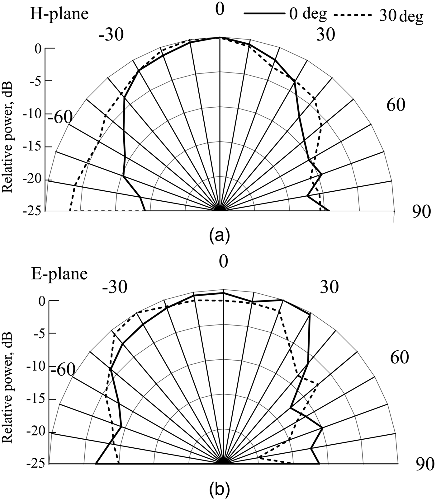
Figure 8 portrays the measured far-field radiation pattern of antenna in the H and E planes for 0 and 30° bend angles. The symmetrical pattern near the standard patch antenna was observed. A loss attributable to the minor lobe was observed slightly for both E and H planes. The results reveal that the bending effect slightly affects the antenna performance.
Far-field radiation pattern of antenna (a) H-plane and (b) E-plane. The 0° bend angle is shown as a solid line. The 30° bend angle is presented as a dotted line.

C) Rectifying circuit design and its bending analysis
1) Rectifying circuit design
Figure 9 presents the single-shunt rectifier on the non-woven fabric substrate and its circuit pattern. A stub on the output filter achieves impedance matching to obtain the properties of a smoothing capacitor [Reference Gutmann and Borrego37]. The threshold voltage and the junction capacitance of the diode (5082-2835; Avago Technologies Ltd.) were, respectively, 0.34 V and 1.0 pF. Because of the high junction capacitance of diode, the transmission line was arranged between a diode and the ground to maximize the diode potential difference between the anode and cathode. The optimum load resistance of the rectifier at the constant input power was measured using a power meter (HP8481A; Agilent Technologies Inc.).
Rectifier circuit on a textile material (left) and equivalent circuit model (right).

For separate discussions of the bending effect for the antenna and the rectifier, an array horn antenna and the standard patch antenna were used to construct an evaluation system of the power incident on the rectenna. The standard patch antenna was used only to evaluate the input power. This system was identical to the MAV demonstration. Details of the array horn antenna are explained in Section IV.
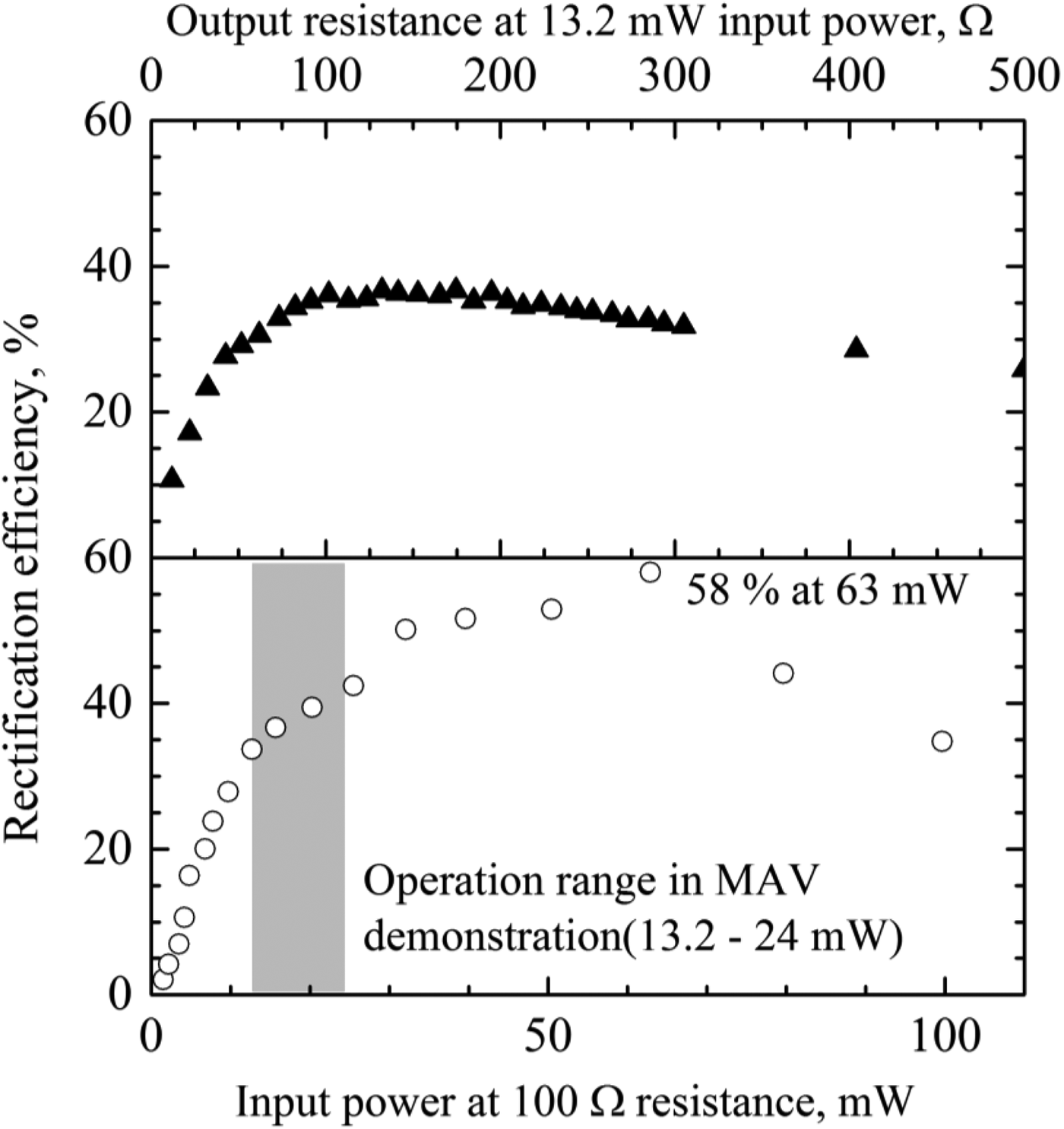
The rectification efficiency and the output voltage as a function of load resistance at 13.2 mW input power are also presented in Fig. 10. As described hereinafter in greater detail, the operation power range of the MAV was 13.2–24 mW because the input power was fixed at 13.2 mW. As a result, the optimum load resistance of the rectifier at 13.2 mW input power was 100 Ω. The same trend was observed at 1–125 mW. Figure 10 shows the RF–DC conversion efficiency with the optimum load resistance at 100 Ω. The common curve of rectifier conversion efficiency was observed. Maximum conversion efficiency of 58% was obtained with the input power at 63 mW. In the power range of the MAV operation, the RF–DC conversion efficiency was 35–43%.
Rectification efficiency versus input power. External load resistance was 100 Ω (lower graph). Rectification efficiency and output voltage versus external load resistance. Input power was fixed at 13.2 mW (upper graph).

2) Performance comparison of rectenna on different substrates
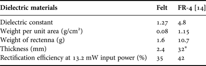
To confirm the benefits of the non-woven fabric rectenna, it was compared with the rectenna using FR-4. For the FR-4 substrate rectenna, the back-feed type antenna and the rectifier circuit were developed on different substrates [Reference Komatsu, Katsunaga, Ozawa, Komurasaki and Arakawa14].
Table 5 shows that the rectification efficiency of the felt rectenna at 13.2 mW input power was slightly lower than that of the FR-4 rectenna. The same rectifier diode was used for all rectenna substrates. The rectenna weight per unit area for the felt substrate at 0.08 g/cm2 was 1/14 the FR-4 substrate size. The benefits of the non-woven fabric substrate include its wide-band frequency and the high radiation efficiency attributable to its low dielectric constant [Reference Tanaka24].
Comparison of rectenna specifications.

* Rectifier circuit was set vertical to the antenna plane.
Even if the microstrip antenna made with a low dielectric constant is larger than that made with a higher dielectric constant, the felt substrate presents benefits in terms of the rectenna weight. Results of the rectenna comparison confirmed the important benefits of the felt rectenna in terms of its weight and rectification efficiency.
3) Effects of bending on RF–DC conversion efficiency
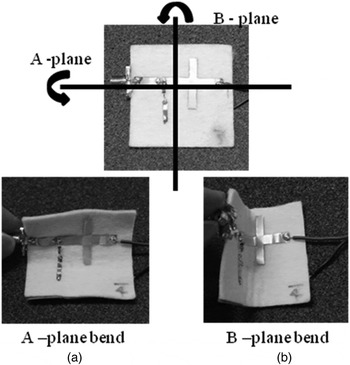
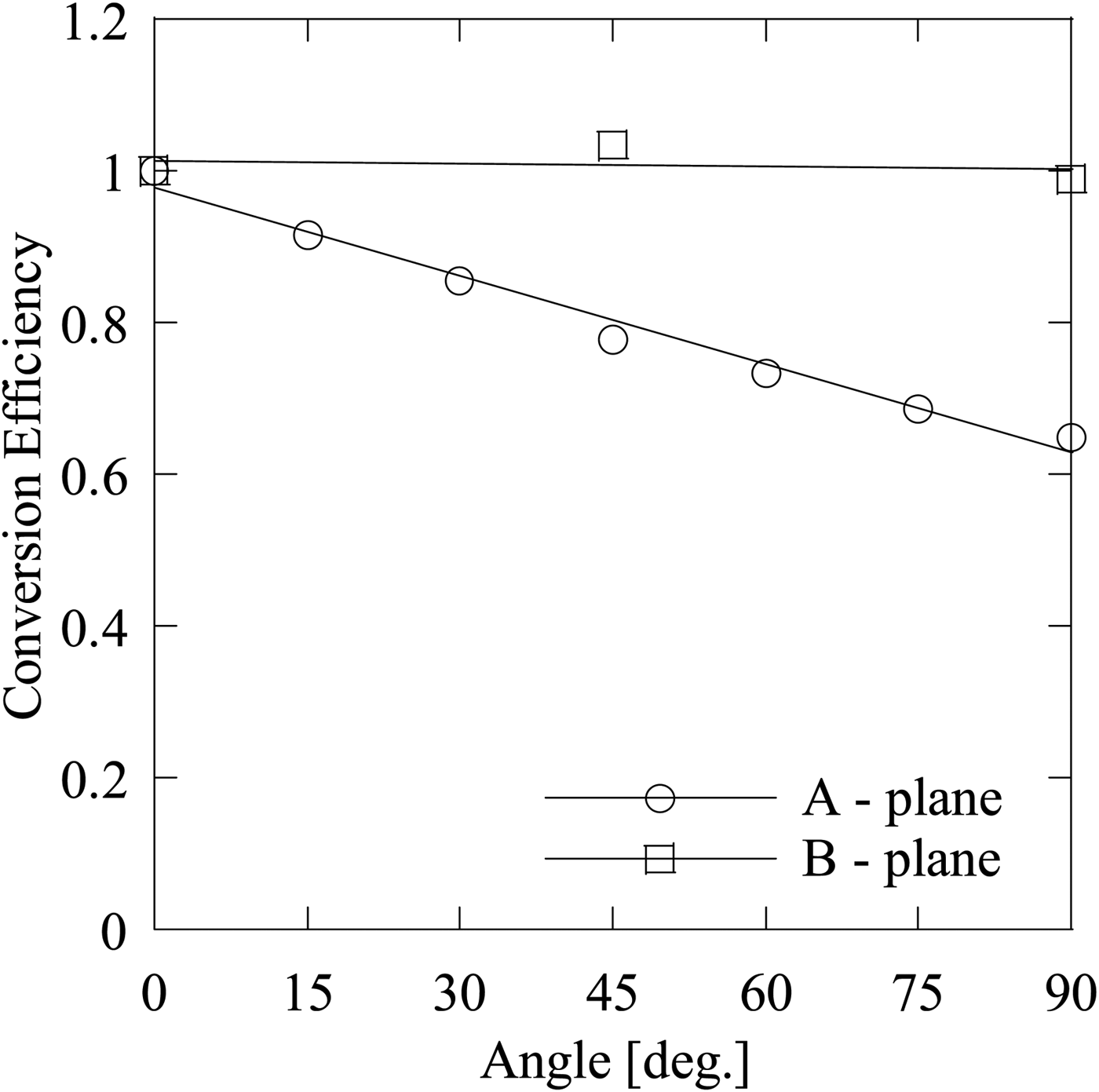
The radiation loss attributable to the microstrip circuit bending depends on the circuit pattern and its curvature [Reference Garg, Bahl and Bozzi38]. To take advantage of a flexible substrate for fitting the curved surface, the rectification efficiency of rectifier circuit under the bent condition was measured as presented in Fig. 11. A-plane bending was defined as the direction along the longitudinal part of the microstrip line. The folding lines for B-plane were located on the center of rectifier circuit between the diode and the stub. The bending angle was defined as the range of 15–90°. Figure 12 exhibits effects of the bending angle on the RF-DC conversion efficiency. In Fig. 12, the RF–DC conversion efficiency of the rectenna was normalized by the normal condition: 0°. As a result of A-plane bending, the RF–DC conversion efficiency was decreased concomitantly with increasing the bending angle. Because A-plane bending occurred along the line between the diode and the ground, the substrate compression with increasing bending angle changes the distance between the diode and the ground. Results show that the change of characteristic impedance for the microstrip circuit affected the reflection loss of alternating current and the loss in the conductors because of Joule heating. However, the conversion efficiency was unchanged under the bent condition for the B-plane. The folding point is the part of DC current. Therefore, the change of the microstrip line attributable to bending of the circuit slightly affected the rectification efficiency. Consequently, the bending effect on the rectification efficiency can be reduced with consideration of the direction of rectifier circuit and the bending direction of the curved surface.
Bend direction of the rectifier circuit.

Bending effects on the relative RF–DC conversion efficiency.

IV. POWER TRANSMISSION AND POSITION TRACKING SYSTEM
A) Software retrodirective antenna array design
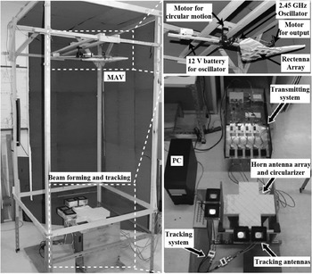
Beam forming and position tracking technology are the most important aspects of microwave power transmission for mobility applications. High-accuracy control techniques are necessary for beam transmission from the ground to the mobility and vice versa. Figure 13 shows that an active phased-array system for 5.8 GHz power transmission and 2.45 GHz software retrodirective system for position tracking were developed.
Software retrodirective system and micro aerial vehicle with a rectenna array.

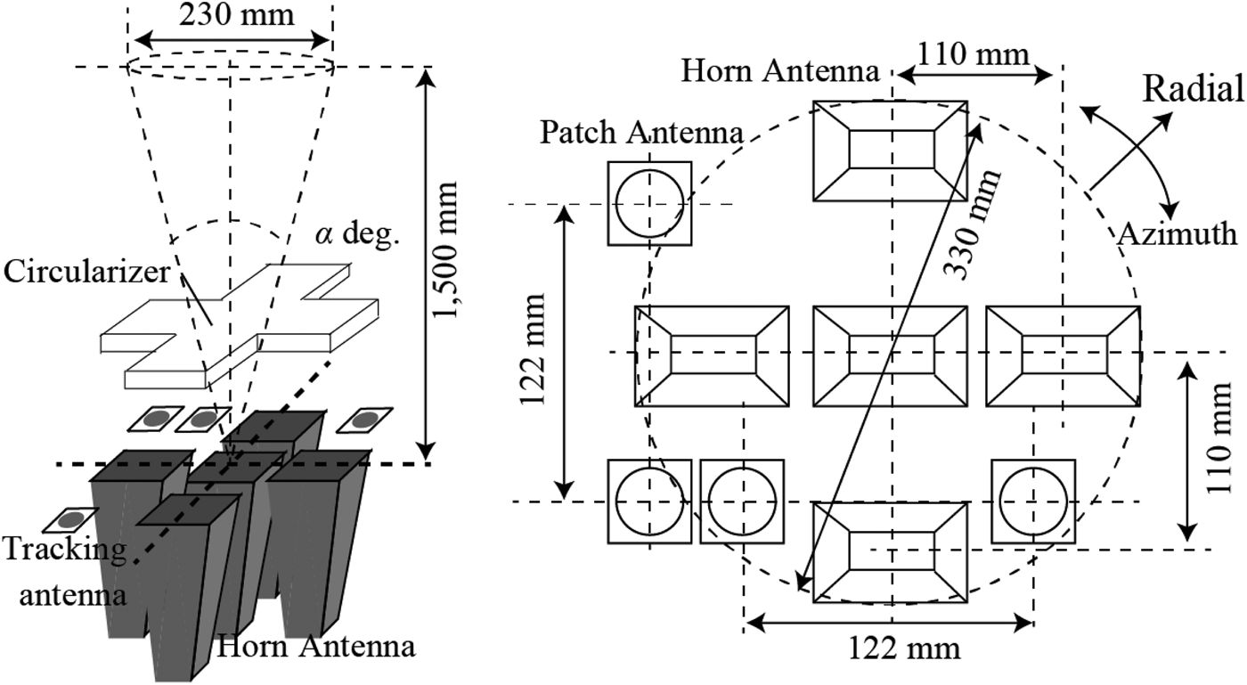
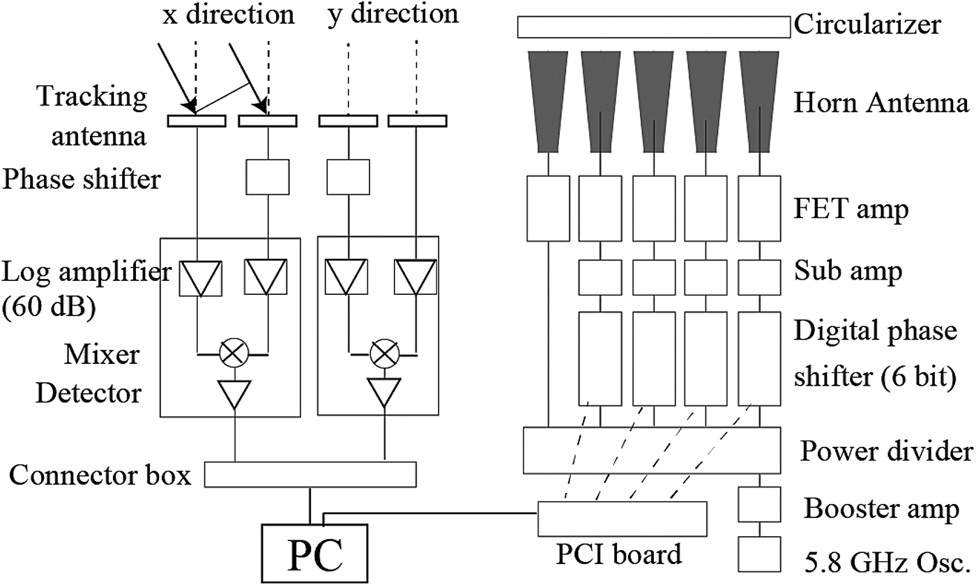
Because the development of autonomous flight MAV and control the flight operations are beyond the scope of these analyses, this report describes specific examinations of transmission efficiency and position tracking error. Two DC motors were used for the demonstration. A 2D position tracking experiment was conducted using a 2.45 GHz pilot signal generator. To demonstrate the position tracking system, the MAV was operated as uniform circular motion on the plane by a DC motor, with 37.0 rpm rotation speed. At altitude from the horn array antenna h = 1500 mm, the antenna on the MAV with 2.45 GHz oscillator was turned at the turning radius 237 mm and the rotation cycle 1.62 s. The other DC motor, which is for the demonstration of power transmission will be discussed in the following section. Figure 14 presents a schematic of an antenna array for power transmission and position tracking. Because the divergence angle of the beam is inversely proportional to the antenna array aperture, the antenna directivity is increased with large antenna aperture. The maximum steering angle is inversely proportional to the antenna spacing, where the maximum steering angle is that at which the main lobe is the same as the grating lobe. To achieve 2D beam formation, the element spacing and the diameter of the horn array antenna were, respectively, 110 and 330 mm. A metal grid circularizer was mounted on the horn array antenna to convert from the linear polarization of the horn antenna to circular polarization [Reference Skolnik39, Reference Kotajima and Kawamura40]. The element spacing of the microstrip antenna for position tracking was identical to the wavelength (122 mm for 2.45 GHz). Figure 15 presents a schematic representation of the active phased-array and position tracking systems. The beam forming and the direction of 5.8 GHz transmission beam were controlled using the horn antenna array, a digital phase system, and an active phased-array system with the tracking position. The MAV position was determined according to the phase shift of the pilot signal. A 5.8 GHz microwave power source was connected to the five-port power divider via a booster amplifier. The power loss associated with the digital phase shifter was compensated by the subamplifier. The field effect transistor (FET) amplifier regulated the power on each line at 1 W. The FET amplifier and the rectangular horn antenna were connected via a 1 m coaxial flexible cable. As a result of power measurements, the total power irradiation was 4.0 W with the 1 dB flexible cable loss. For the position tracking system, the two pairs of the microstrip tracking antenna, respectively, receive the pilot signal for x- and y-axes. After receiving the pilot signal, the 90° phase difference was applied to one of the pair microstrip antennas. Each signal passed through the 60 dB log amplifiers and was combined using a mixer. The incident angles of the tracking signal for x- and y-axes were calculated using a LabVIEW program. Results show that the incident angle of pilot signal α in the range of −12° ≤ α ≤ 12° was available for x- and y-directions.
Schematic of antenna array for power transmission and position tracking.

Schematic of active phased-array and position tracking systems.

The single 2.45 GHz right-hand circular-polarized antenna for the tracking position using the non-woven fabric substrate was also loaded on the center of the MAV. The distance between the MAV and the transmitting horn antenna array was 1500 mm. The turning radius was 237 mm with consideration of the 9° beam steering angle.
B) Beam forming distribution and position tracking error
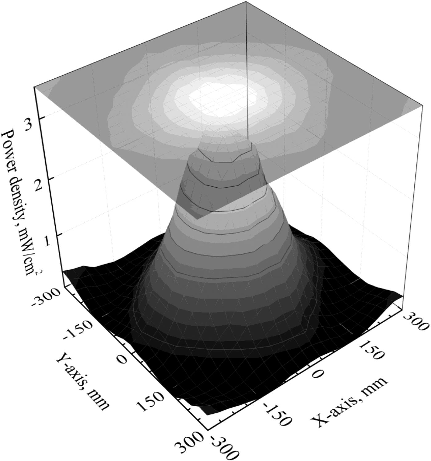
To measure the power intensity distribution of the MAV operation plane at h = 1500 mm, the circular-polarized patch antenna and a power detector (8481A and 437B; Hewlett Packard Co.) were used. The digital phase shifters were set to obtain the maximum power intensity distribution. Figure 16 portrays the distribution of radiation power density at 1500 mm distance from the array antenna aperture. Energy distribution at the rectenna was the Gaussian distribution (or beams) with optimized conditions [Reference Shinohara31]. The beam quality factor is a common measure of the laser beam quality. The beam quality and divergence angle of the microwave beam were, respectively, 1.6° and 9°.
Two-dimensional power intensity distribution map at h = 1500 mm.

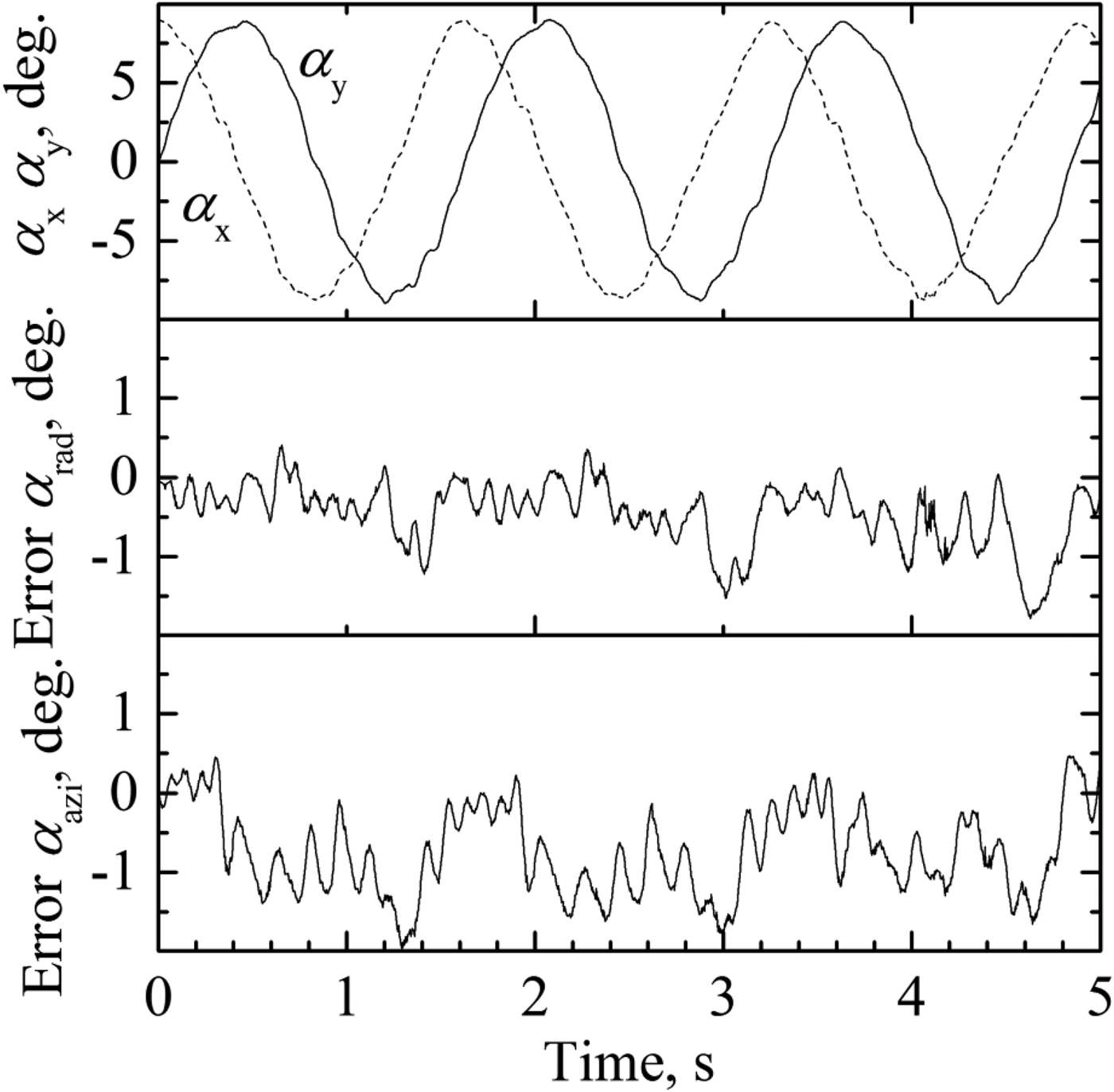
Figure 17 presents the evaluated incident angle for x- and y-directions. The time period and the magnitude of angle were, respectively, 1.62 s and ± 9°. Results revealed that the position tracking system operated successfully. As presented in Fig. 17, the tracking error of the azimuth and radial direction in this system were, respectively, −1.97° ≤ αazi ≤ 0.47° and −1.79° ≤ αrad ≤ 0.41°.
Evaluated incident angles αx and αy , and tracking error of the azimuth and radial direction. The transmission distance, turning radius, and rotation cycle are, respectively, 1500, 237 mm, and 1.62 s.

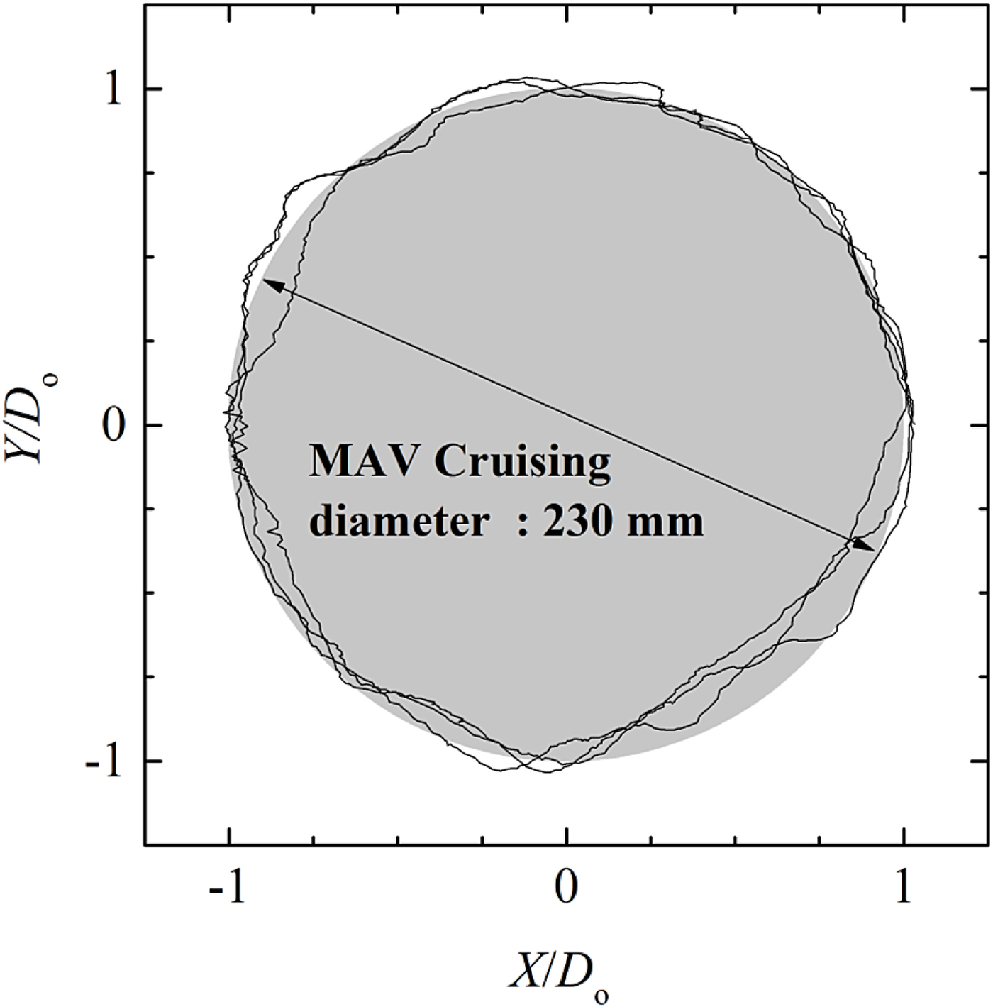
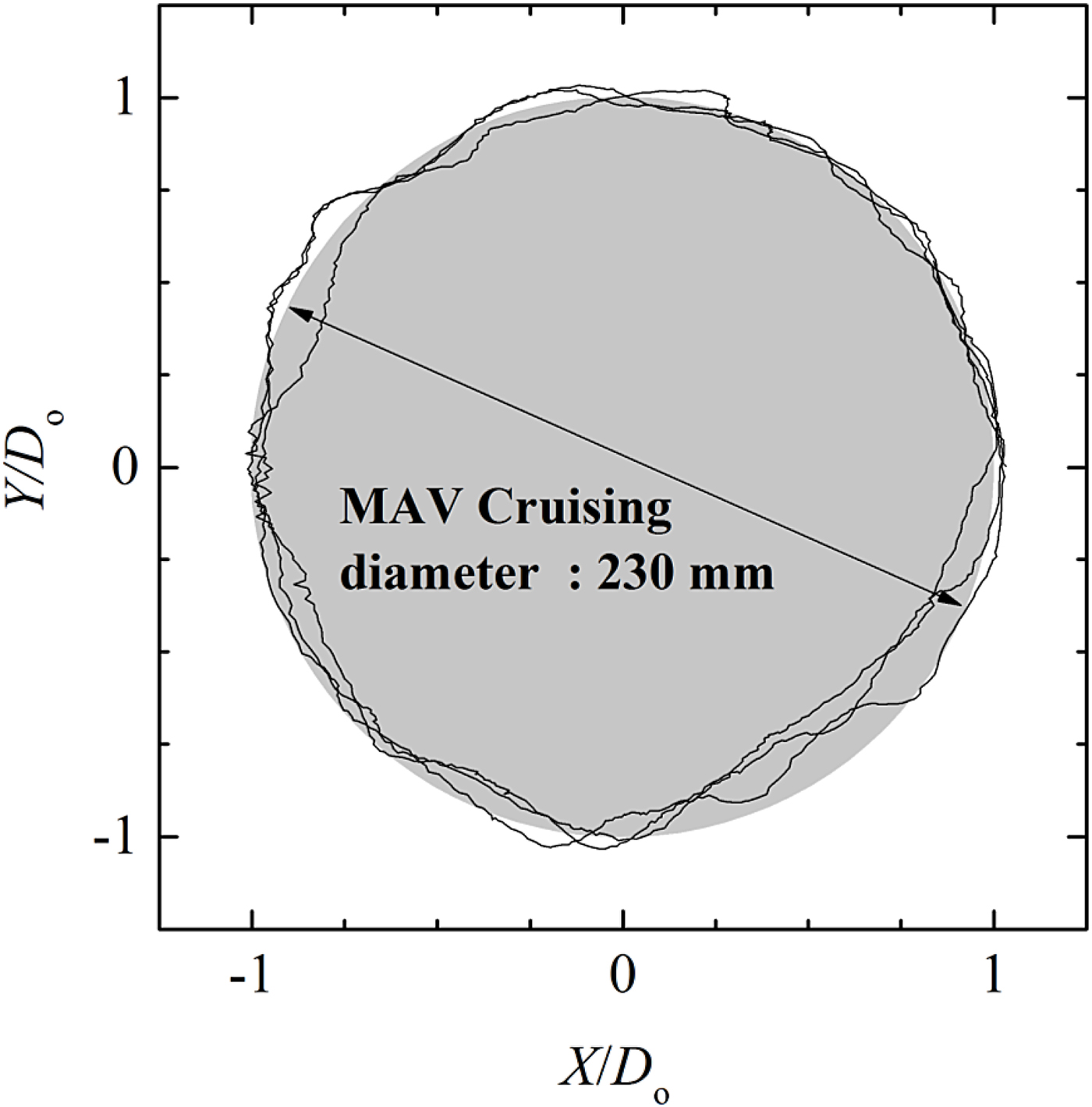
Figure 18 presents the position tracking trace with the MAV operation circle at h = 1500 mm. The x- and y-directions are divided by the operation diameter. The tracking trace was almost on the MAV operation circle. Considering the divergence angle of transmitting beam at 9°, the tracking system accuracy is sufficient for power transmission.
MAV trajectory and the position tracking trace with the dimensionless parameter Y/Do and X/Do at h = 1500 mm.
C) MAV design
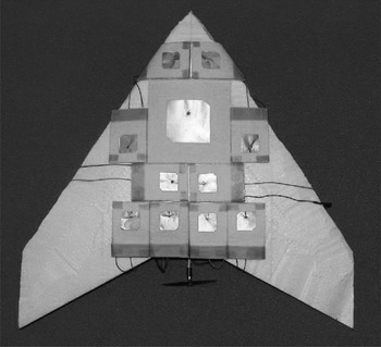
For this study, 10 multiple rectennas were connected in parallel and were loaded on the back-surface of the MAV as presented in Fig. 19. Shinohara and Matsumoto revealed that the output power of parallel connected rectenna array is higher than that of a series connected rectenna array using two rectenna elements [Reference Shinohara and Matsumoto41]. Furthermore, the total output power of the rectenna array decreases concomitantly with increased output difference of rectennas despite the parallel or series connection. Power gathered from each rectenna element was combined at the DC level. The total weight of the MAV was 103 g. The effective area for the single element was 1930 mm2. To demonstrate the power transmission, an electric toy motor with a propeller was connected to the combined DC system. Although the load of the motor at 10 Ω was less than the optimized resistance at 100 Ω for the rectenna, the motor weight was 2.8 g. The minimum operation power was 1 mW. Because of the low input power and light weight, a small DC motor with 10 Ω resistance was used.
Reverse side of the micro aerial vehicle with the 5.8 GHz rectennas and a 2.45 GHz RHCP microstrip patch antenna for the tracking signal.

D) Received power of turning flight MAV and total transmission efficiency
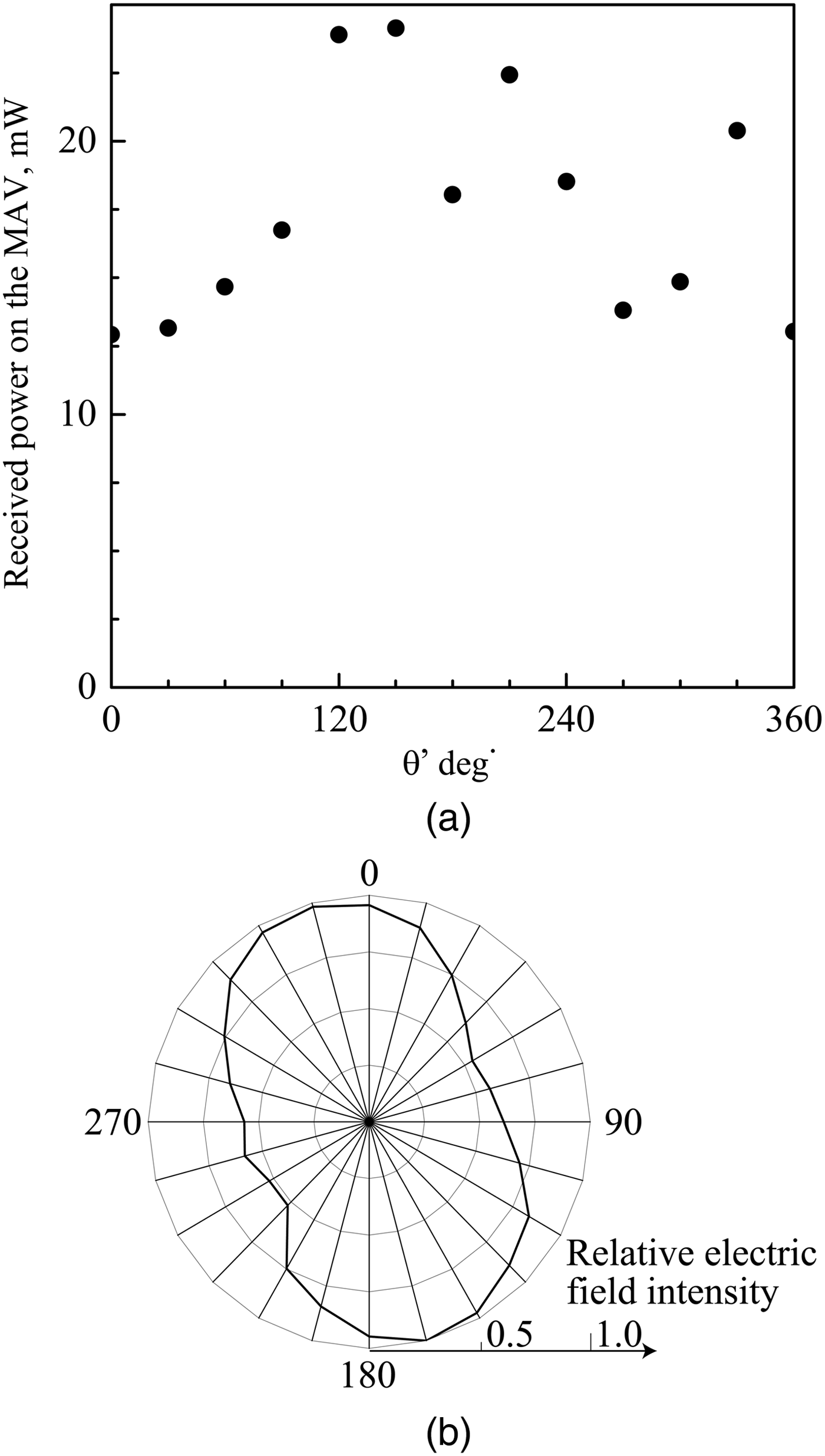
Figure 20 presents the received power of the multiple rectennas as a function of the turning flight angle. As shown in Fig. 20(a), results show that the average and maximum received power of the multiple rectennas were, respectively, 17.6 and 24 mW. Because of the yaw angle dependence for the antenna and transmission wave, the received power on the MAV changed along with the circular position. Because the rectification efficiency depends on the input power, the conversion efficiency fluctuated along with the transmission angle. To evaluate the circular-polarization pattern of the beam, a dipole antenna with the detector was used. The power was recorded for the fixed distance on MAV plane. The circularly polarized field pattern of the transmission horn array antenna at 1500 mm distance from the array antenna aperture is presented in Fig. 20(b). Because the polarization was not completely circular polarization, the angle of maximum input power corresponded to the circularly polarized field pattern of the transmission horn array antenna. The average and maximum total transmission efficiencies (ηT,av and ηT,max ) were measured, respectively, at 0.44 and 0.60%. The total efficiency from the transmitting antenna aperture to the DC output ηT,est is expressed as a product of some efficiency of each component.
 $$\eta _{T,est{\rm} =} \eta _{beam} \times \eta _{pol} \times \eta _{ant} \times \eta _{ret} \times \eta _{RF}.$$
The transmitted power from the horn antenna array was 4.0 W. The radiated power in the main lobe at a 9° beam steering angle per total radiated power ηbeam was 0.33. The main lobe area at 1500 mm transmission distance was 173 000 mm2. The efficient area of received antenna was 1930 mm2 × 10 elements. Therefore, the capture efficiency ηant was 0.112. The efficiency of the polarized wave ηpol and the antenna return loss ηret were, respectively, 0.7 and 0.9. The RF–DC conversion efficiency ηRF was 0.37 at the maximum RF input at 24 mW. Consequently, the total power-transmission efficiency in the present system ηT,est was estimated at 0.86%. The measured total efficiency of power transmission ηT,max was slightly smaller than the estimated efficiency ηT,est because the misalignment between the Gaussian beam center and the multiple rectennas might decrease the efficiency ηbeam and ηant in the measurement. The rectenna connections and output difference of rectennas also affect the lower value of measured total efficiency on the MAV [Reference Shinohara and Matsumoto41].
(a) Received power of turning flight MAV and (b) circular-polarization pattern of the beam.

V. FEASIBLITY ANALYSIS OF WIRELESS POWER TRANSMISSION SYSTEM FOR MAV
To investigate the specifications of wireless power transmission system using radio waves, it is convenient to use a simple calculation of the beam collection efficiency by a circular aperture antenna. Assuming that the influence of atmospheric absorption on radio wave propagation is negligibly small, the radio wave is radiated uniformly by the circular aperture transmitter antenna and received by a circular aperture receiver antenna. By Friis's equation, the beam collection efficiency is obtained approximately as [Reference Shinohara42]
 $$\eta = 1 - e^{ - \tau ^2},\;\tau = \displaystyle{{A_TA_R} \over {{(\lambda d)}^2}},$$
where AT , AR , λ, and d, respectively, represent the aperture area of transmitting antenna, the aperture area of receiving antenna, the wavelength, and the transmission distance. Using Equation (5), the transmitting power can be estimated as
 $$P = \eta _TP_{in}\left[ {1 - \exp \left( { - \displaystyle{{\pi k^2S} \over {16}}} \right)} \right],\;\;k = \displaystyle{{fD_T} \over {cd}},$$
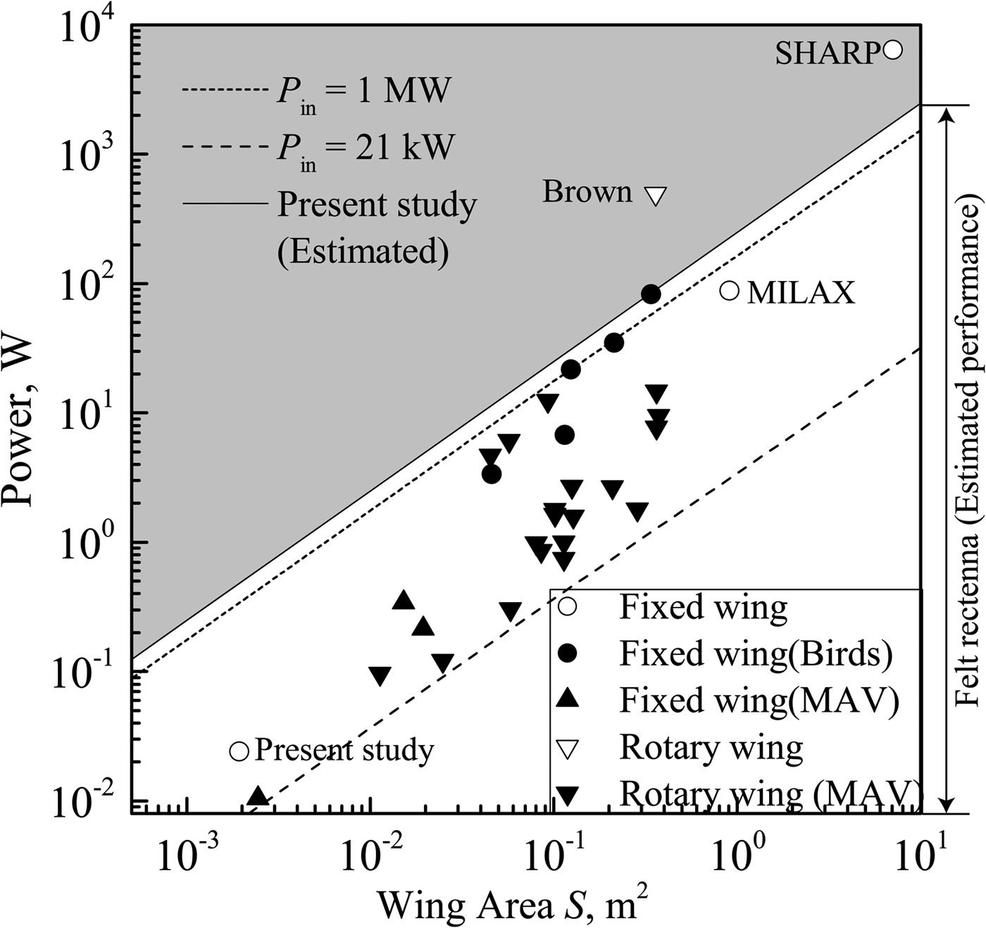
where Pin , S, f, DT , and c, respectively, denote the input power on the transmitting antenna, the wing area, the radio wave frequency, the transmitting antenna diameter, and the speed of light. ηT was assumed at 0.6%. The aperture area of receiving antenna AT is replaced as the wing area S. Figure 21 presents a flight diagram of MAVs and the required power for non-accelerated flight. Flight specifications were obtained from earlier reports of the literature [Reference Pines and Bohorquez1, Reference Mukherjee, Heiges and Matthies16, Reference Shyy, Berg and Ljungqvist43]. Assuming that d, DT , and ηT are, respectively, 50 m, 1 m, and 0.6%, the operation power ranges Pin of 21 kW and 1 MW are presented in Fig. 18. The shade region represents the out-of-operation range for the felt rectenna assuming optimum operation condition with ηRF = 0.58 and ηpol = ηant = ηret = 1. The turning radius at 50 m altitude is estimated as 8 m. Results reveal that the power supply using the felt rectenna with the optimized condition covers most of the MAV requirements.
Flight diagram gives a relation between MAVs and the power transmission estimated by equation (6). The shaded region shows the out-of-operation range for the felt rectenna [Reference Pines and Bohorquez1, Reference Schlesak and Alden5, Reference Fujino6, Reference Mukherjee, Heiges and Matthies16, Reference Shyy, Berg and Ljungqvist43].

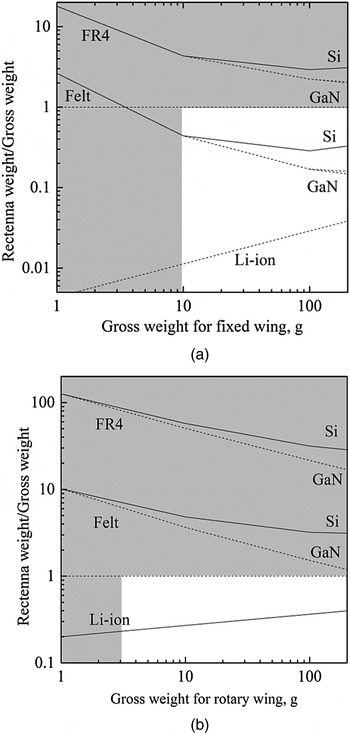
To attempt microwave power transmission, the rectenna performance in terms of the weight is important for MAVs. Figure 22 shows the rectenna weight per gross weight for the fixed wing and the rotary wing. The FR4 and felt substrate and the Li-ion battery are compared. Recently, a GaN Schottky was developed for the microwave rectifier; 5 W input power will be available from GaN Schottky [Reference Takahashi44]. The GaN Schottky diodes are compared with the conventional Si Schottky diode. The shaded region denotes out of MAV operation adopted from Fig. 22. The rectenna weight per gross weight decreases concomitantly with increasing gross weight. For the fixed wing, the weight of felt rectenna with the Si diode is less than the gross weight. Although the rectenna weight is greater than that of the Li-ion battery, the rectenna weight per unit of gross weight with the Si Schottky diode and GaN Schottky diode are, respectively, 0.29 and 0.17 when the gross weight is 100 g. Consequently, it is possible to apply the microwave power transmission for fixed wing MAVs. Furthermore, the GaN Schottky diode enables improvement of the felt rectenna performance. It is difficult to attempt the microwave power transmission for the rotary wing MAVs. The integrated techniques for the rectifier and the high-power Schottky diode might improve the rectenna performance. The microwave power transmission increases the MAV endurance. Consequently, the present paper showed the preliminary flight demonstration of MAVs and presented the possibility of microwave powered transmission. Further MAVs demonstration is important to provide the more accurate feasibility study.
Rectenna weight per unit of gross weight for (a) the fixed wing and (b) the rotary wing. The shade region shows the MAV out-of-operation area.

VI. CONCLUSION
To attempt WPT via microwave for MAVs, the non-woven fabric substrate was used to develop a lightweight and flexible rectenna. A rectification circuit was produced on the back side felt while sandwiching a copper foil as a ground plate. The return loss of microstrip patch antenna RL was increased with the bending angle, RL = 12.3 dB at 45°. The microstrip patch antenna under a 45° bent condition satisfied the low-loss reflection antenna condition. AR <3 dB was maintained when the antenna bend angle was <30°. The maximum conversion efficiency of 58% input power was obtained at 63 mW. In the power range of MAV operation from 13.2 to 24.0 mW, the RF-DC conversion efficiency was 35–43%. Along the bend direction for the longitudinal part of microstrip line, the RF–DC conversion efficiency decreased concomitantly with increasing bend angle. To demonstrate the non-woven rectenna, power transmission using the MAV was performed with the 2.45 GHz retrodirective system. Results show that the average and maximum received power of the multiple felt rectennas on the MAV surface were, respectively, 17.6 and 24 mW. The feasibility of wireless power transmission system via microwaves for MAVs was evaluated. The felt rectenna enables the use of microwave power transmission for fixed wing type MAVs.
ACKNOWLEDGEMENTS
The authors thank Professors Kouji Tanaka and Susumu Sasaki of the Japan Aerospace Exploration Agency for helpful discussion and support. This work was supported in part by a Grant-in-Aid for Young Scientists (b), No. 16K18306, supported by the Ministry of Education, Culture, Sports, Science and Technology (MEXT), Japan.
 Kohei Shimamura received a B.S. degree in Engineering from Keio University, Yokohama, Japan, in 2009; and M.S. and Ph.D. degrees in Science from the University of Tokyo, Chiba, Japan, in 2011 and 2014, respectively. Since 2014, he has been an Assistant Professor in the Department of Engineering Mechanics and Energy, University of Tsukuba, Ibaraki, Japan.
 Hironori Sawahara received a B.S. degree in Engineering from the University of Tsukuba, Ibaraki, Japan, in 2009 and M.S. degree of Science from the University of Tokyo, Chiba, Japan, in 2011.
 Akinori Oda received the M.S. degree of Science from the University of Tokyo, Chiba, Japan, in 2011. He joined DENSO Corporation in 2011, and has worked on production engineering of EHV power module and millimeter-wave radar.
 Shunsuke Minakawa received a B.S. degree in Engineering from the University of Tsukuba, Ibaraki, Japan, in 2016. He is currently in a M.S. course of the University of Tsukuba.
 Sei Mizojiri is currently in a B.S. course of the University of Tsukuba, Ibaraki, Japan.
 Satoru Suganuma is currently in a B.S. course of the University of Tsukuba, Ibaraki, Japan.
 Koichi Mori received, respectively, the B.S., M.S., and Ph.D. degrees from the University of Tokyo, Tokyo, Japan, in 1999, 2001, and 2004. He has been an Associate Professor of the Department of Aerospace Engineering, Nagoya University, Aichi, Japan.
 Kimiya Komurasaki received, respectively, the B.S., M.S., and Ph.D. degrees from the University of Tokyo, Tokyo, Japan, in 1987, 1989, and 1992. He has been a Professor of the Department of Aeronautics and Astronautics, the University of Tokyo, Chiba, Japan.