

I. INTRODUCTION
Recently, perovskite oxide thin films have attracted much attention because of their potential applications in random access memories, thin-film capacitors, and field effect transistors, due to their excellent dielectric, piezoelectric, and ferroelectric properties.Reference Scott1–Reference Martin and Rappe3 Elastic strains from lattice mismatch between substrates and stress-free films are generally used to tune the properties of perovskite oxide thin films, which is named “strain engineering.”Reference Schlom, Chen, Fennie, Gopalan, Muller, Pan, Ramesh and Uecker4
In the past decades, many studies indicated that interfacial defects such as misfit dislocations (MDs) not only affect domain configurations,Reference Hu, Li and Chen5–Reference Liu, Tang, Zhu, Wang and Ma7 but also deteriorate the dielectric, piezoelectric, and ferroelectric properties of perovskite oxide thin films, such as pinning domain walls and reducing the local spontaneous polarization.Reference Chu, Szafraniak, Scholz, Harnagea, Hesse, Alexe and Gosele8–Reference Gao, Nelson, Jokisaari, Baek, Bark, Zhang, Wang, Schlom, Eom and Pan11 Formation of interfacial MDs can relax the elastic strain when the film thickness exceeds the critical value in epitaxial thin films and then reduce the strain tuning ability of substrates.Reference Jain, Harker and Cowley12 Besides, the threading dislocations in films are known to increase the surface roughness of thin films. Nevertheless, a recent study using phase-field simulations demonstrated a beneficial phenomenon that the proper dislocation intensity can reduce the coercive field and meanwhile enhance the remanent polarization of a ferroelectric single crystal.Reference Wu, Wang, Cao and Zhang13 Experimentally, a periodic interfacial MD array in a BiFeO3/LaAlO3(001) nanostructure results in a giant strain gradient and consequently enhances the visible light absorption property.Reference Tang, Zhu, Liu, Wang and Ma14 All these studies indicate that the effects of dislocations on physical properties of perovskite oxide thin films are not clarified so far. Thus, it is essential to systematically investigate the configuration of interfacial MDs and misfit strain relaxation behavior of perovskite ferroelectric thin films to better understand the effect of MDs on the physical properties of perovskite oxide thin films.
For decades, MDs in perovskite ferroelectric thin films have been widely studied. For example, Stemmer et al. observed MDs with Burgers vectors of 1/2a〈010〉 and a〈010〉 in (001)-oriented PbTiO3/MgO and PbTiO3/SrTiO3 thin films, respectively.Reference Stemmer, Streiffer, Ernst and Ruhle15 Other researchers also found MDs with Burgers vectors of a〈010〉, threading dislocations with Burgers vectors of a〈110〉 in (001)-oriented BaTiO3/SrTiO3 thin films,Reference Suzuki, Nishi and Fujimoto16 and MDs with Burgers vectors of a〈110〉 and 1/2a〈110〉 in (001)-oriented Nb:SrTiO3/SrTiO3 thin films.Reference Zhu, Ma, Li, Lu, Chen and Yang17 Similar studies were performed in other (001)-oriented perovskite thin films, such as Pb(Zr, Ti)O3 and SrTiO3.Reference Chu, Szafraniak, Scholz, Harnagea, Hesse, Alexe and Gosele8–Reference Jia, Mi, Urban, Vrejoiu, Alexe and Hesse10,Reference Misirlioglu, Vasiliev, Alpay, Aindow and Ramesh18,Reference Qin, Jia, Urban, Hao and Xi19 Usually, in (001)-oriented perovskite thin films, the interfacial MDs exhibit Burgers vectors of a〈010〉, a〈110〉, 1/2a〈010〉, and 1/2a〈110〉, respectively. All of these dislocations have a line direction of 〈100〉, and they are usually formed by gliding, dislocation reaction, and dislocation half-loop mechanism.Reference Tang, Zhu, Liu, Wang and Ma14–Reference Zhu, Ma, Li, Lu, Chen and Yang17 Nevertheless, so far, most of the studies have focused on the (001)-oriented epitaxial thin films. Experimental observations on MDs and misfit strain relaxation behavior in other oriented perovskite thin films have not been widely studied. Although several reports on the MD configuration and high-density stacking faults in (110)-oriented Nd0.45Sr0.55MnO3,Reference Tang, Zhu, Meng, Zhang and Ma20,Reference Tang, Zhu, Zhang, Zhang and Ma21 interfacial MDs in (111)-oriented (Ba0.7Sr0.3)TiO3, and PbTiO3 thin films were published previously,Reference Shen, Yamada, Lin, Kamo, Funakubo, Wu, Xin and Su22,Reference Xu, Tang, Zhu, Liu, Li, Zhang and Ma23 the misfit strain relaxation behavior for {110}-oriented epitaxial thin films has still not been investigated. Especially, the complex domain structures in (101)-oriented tetragonal ferroelectric PbTiO3 and Pb(Zr0.2Ti0.8)O3 thin films complicate the misfit strain relaxation behavior in these thin films.Reference Mtebwa, Mazzalai, Sandu, Crassous and Setter24,Reference Feng, Tang, Ma, Zhu, Zou, Han, Ma and Ma25 Furthermore, theoretical simulations and experimental studies have shown that dielectric and piezoelectric responses are enhanced due to high domain wall density in (101)- and (111)-oriented tetragonal ferroelectric Pb(Zr0.2Ti0.8)O3 thin films.Reference Xu, Karthik, Damodaran and Martin26–Reference Zhang, Cheng, Yang, Hu and Ouyang28
In this work, using transmission electron microscopy (TEM), including diffraction contrast analysis and aberration-corrected high-angle annular dark field (HAADF) scanning transmission electron microcopy (STEM), we investigate the interfacial MDs and misfit strain relaxation behavior of typical tetragonal ferroelectric PbTiO3 (PTO) thin films deposited on (101)-oriented (La, Sr)(Al, Ta)O3 (LSAT) substrates. Two types of MDs, named 〈111〉 MDs and [010] MDs, are observed. The former are mixed dislocations generated by gliding, and the latter are pure edge dislocations formed by climbing. Detailed analysis indicates that the lattice mismatch between strain-free PTO thin film and LSAT substrate is mainly relaxed by interfacial MDs and the residual misfit strain is relaxed by forming 90° ac domains.
II. RESULTS
A. General information
At room temperature, PTO is a typical tetragonal ferroelectric with the space group of P4mm and lattice parameters of a = b = 0.390 nm and c = 0.415 nm.Reference Glazer and Mabud29 LSAT is a cubic crystal with the space group of  $Fm\bar{3}m$ and lattice parameters of a = b = c = 0.3868 nm.Reference Mateika, Kohler, Laudan and Volkel30 It is worthwhile to mention that LSAT(101) substrate has two different in-plane orthogonal axes of [010] and
 $\left[ {\bar{1}01} \right]$, which are frequently used in TEM observations of (101)-oriented PTO thin films.
B. Microstructures of interfacial MDs
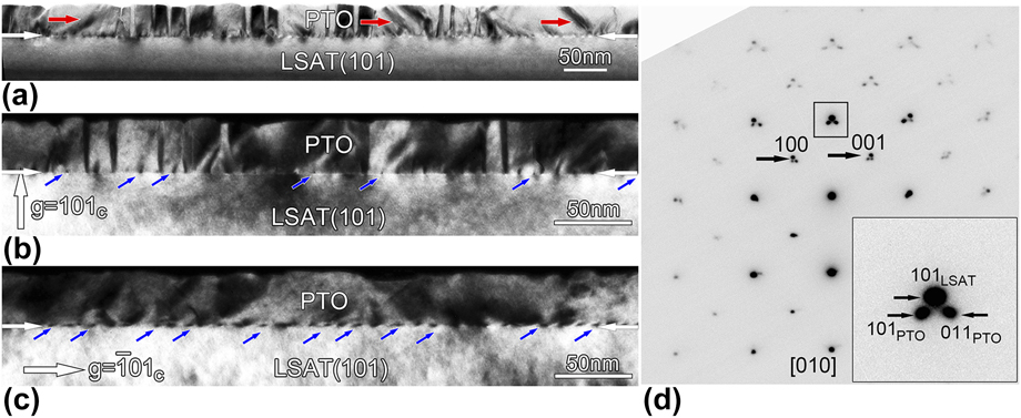
Figure 1(a) shows a cross-sectional bright-field image of [101]PTO thin films taken along the in-plane [010] zone axis of LSAT. The interface between PTO film and LSAT substrate is denoted by a pair of white arrows. The film thickness is about 35 nm. Many vertical stripe domains with alternately bright and dark contrast and a small number of inclined domains (denoted by red arrows) with an inclination angle of about 45° can be seen in the PTO thin film. These domains are 90° c 1/c 2 domains and 90° a/c domains, respectively, as observed in the previous studies.Reference Mtebwa, Mazzalai, Sandu, Crassous and Setter24,Reference Feng, Tang, Ma, Zhu, Zou, Han, Ma and Ma25 The 90° a/c domain wall is indistinct due to non-edge-on effect. Besides, as shown in Fig. 1(a), a high density of black dots appear at the PTO/LSAT(101) interface, which might be interfacial MDs. Figures 1(b) and 1(c) are two-beam dark-field images obtained near the in-plane [010] zone axis of LSAT taken with different reflections of g = 101c and  ${\bf{g}} = \bar{1}{01_{\rm{c}}}$, respectively, where the subscript “c” denotes cubic LSAT substrate. It is seen that the stripe domains are clearly visible when imaged with a reflection of g = 101c, while the stripe domains are invisible when imaged with a reflection of
 ${\bf{g}} = \bar{1}{01_{\rm{c}}}$. This is because of the fact that the diffraction spots of 90° c 1/c 2 stripe domains split remarkably along the out-of-plane direction and slightly in the in-plane direction [Fig. 1(d)], which agrees well with our previous study.Reference Feng, Tang, Ma, Zhu, Zou, Han, Ma and Ma25 Meanwhile, the appearance of interfacial MDs shows a higher density when taken with reflection of
 ${\bf{g}} = \bar{1}{01_{\rm{c}}}$, indicating that there are at least two types of MDs at the PTO/LSAT(101) interface. Figure 1(d) is a selected area electron diffraction (SAED) pattern taken along the [010] zone axis of the 35-nm-thick PTO film. The inset is the enlarged area of out-of-plane (101) diffraction spots corresponding to the white rectangular box in Fig. 1(d). As d 110 = d 101 = 0.274 nm for LSAT, and d 110 = 0.276 nm and d 101 = 0.284 nm for PTO, the relationship of
 $d_{101}^{{\rm{LSAT}}} \approx d_{110}^{{\rm{PTO}}} \lt d_{101}^{{\rm{PTO}}}$ can be deduced. Therefore, in the inset, the above spot can be labeled as 101 of LSAT, while the other two spots are labeled as 101 and 011 of PTO, respectively. This indicates that the PTO film grown on LSAT(101) substrate is (101)-oriented.
Cross-sectional TEM images of 35-nm-thick PTO thin films on LSAT substrates. (a) Bright-field TEM image obtained near the [010] zone axis of LSAT. Some 90° a/c domains appear in PTO thin film as denoted by red arrows. (b) Two-beam dark-field image obtained near the [010] zone axis of LSAT taken with g = 101c. (c) Two-beam dark-field image obtained near the [010] zone axis of LSAT taken with  ${\bf{g}} = \bar{1}{01_{\rm{c}}}$. Note a high density of black dot-like defects is accumulated at the PTO/LSAT(101) interface as denoted by arrows. (d) SAED patterns taken along the [010] zone axis including the PTO film and LSAT substrate. The inset is the enlarged area corresponding to the white rectangular box in (d).
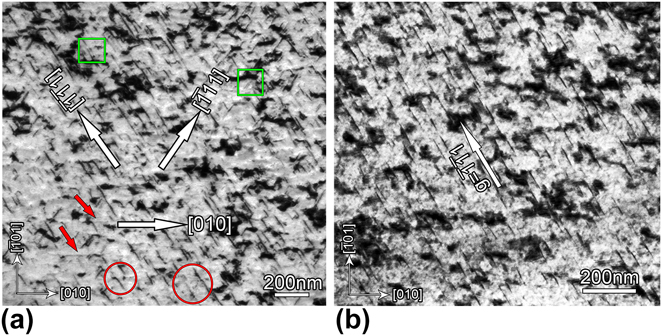
To accurately identify the line directions of the interfacial MDs, plane-view TEM observations are performed. Figure 2(a) is a plane-view bright-field image obtained near the out-of-plane [101] zone axis of LSAT. Three sets of dislocation lines along [010],  $\left[ {\bar{1}\bar{1}1} \right]$, and
 $\left[ {\bar{1}11} \right]$ directions of LSAT are seen, as marked with white arrows. The great majority of dislocation lines are along
 $\left[ {\bar{1}\bar{1}1} \right]$ and
 $\left[ {\bar{1}11} \right]$ directions, while some dislocation lines (pointed by red arrows) are along the [010] direction. Besides, as shown in Fig. 2(a), the spaces of adjacent 〈111〉 dislocation lines in the areas labeled as green rectangles are several nanometers, while the spaces of adjacent 〈111〉 dislocation lines in the areas labeled as red circles are dozens of nanometers, which indicates that the spaces of 〈111〉 dislocation lines are inhomogeneous. This shows that the (101)-oriented PTO thin films grown on LSAT(101) substrates have asymmetric biaxial compressive strains,Reference Feng, Tang, Ma, Zhu, Zou, Han, Ma and Ma25 which might result in the inhomogeneous distributions of 〈111〉 dislocation lines. To analyze the types of dislocations with the dislocation lines along 〈111〉 directions, a two-beam bright-field image is obtained with a reflection of
 ${\bf{g}} = \bar{1}\bar{1}1$, as shown in Fig. 2(b). The dislocation lines along the
 $\left[ {\bar{1}11} \right]$ direction are invisible, while the dislocation lines along the
 $\left[ {\bar{1}\bar{1}1} \right]$ direction are still clearly visible. It is well known that dislocations with a Burgers vector b disappear in a two-beam bright-field image with a reflection of g when it satisfies the invisibility criterion: g ∣ b = 0.Reference Williams and Carter31 Thus, dislocations with dislocation lines
 ${\bi{l}} = \left[ {\bar{1}\bar{1}1} \right]$ do not satisfy the relationship: l ∣ b = 0. Meanwhile, taking into account the crystallographical equivalence between
 $\left[ {\bar{1}\bar{1}1} \right]$ and
 $\left[ {\bar{1}11} \right]$ directions, we propose that MDs with dislocation lines along 〈111〉 directions are not pure edge dislocations.
Plane-view TEM images of 35-nm-thick PTO films on LSAT(101) substrates. (a) The bright field image obtained near the [101] zone axis of LSAT. The main two sets of dislocation lines with directions along  $\left[ {\bar{1}\bar{1}1} \right]$ and
 $\left[ {\bar{1}11} \right]$ were observed. Besides, the dislocation lines with directions along [010] are occasionally identified as denoted by white arrows. (b) Two-beam bright field image obtained near the [101] zone axis of LSAT taken with
 ${\bf{g}} = \bar{1}\bar{1}1$. Note that the dislocation lines with directions along
 $\left[ {\bar{1}11} \right]$ disappear, while the dislocation lines with directions along the
 $\left[ {\bar{1}\bar{1}1} \right]$ still exist.
C. Low-magnification HAADF-STEM imaging and strain field analysis of interfacial MDs
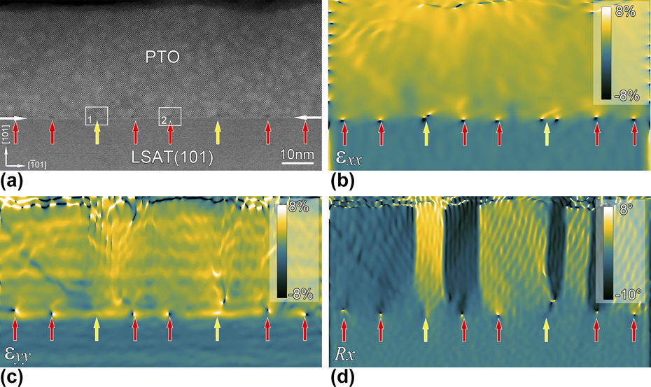
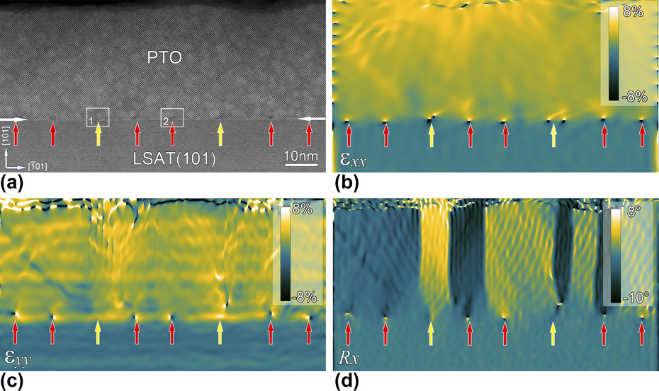
The HAADF-STEM imaging is used to investigate the details of interfacial MDs at atomic scale. Figure 3(a) shows a low-magnification HAADF-STEM image of 35-nm-thick PTO/LSAT(101) films taken along the in-plane [010] direction of LSAT. The intensity of HAADF-STEM image is approximately proportional to Z 2, where Z denotes the atomic number of corresponding elements.Reference Pennycook and Jesson32 The atomic numbers of heavy Pb (82) and light La (57) and Sr (38) atoms are remarkably different, so the interface between the PTO film and LSAT(101) substrate is clearly seen as labeled by a pair of opposite white arrows. An array of interfacial MDs is identified at the interface as denoted by yellow and red arrows, which reveal two different types of MDs. Geometric phase analysis (GPA) is performed to extract the unique strain distributions at the MD cores, which is an effective and accurate method to show complex strain distributions at a long range.Reference Hytch, Snoeck and Kilaas33,Reference Tang, Zhu and Ma34 Figures 3(b)–3(d) are in-plane strain (εxx), out-of-plane strain (εyy), and lattice rotation (R x) maps corresponding to Fig. 3(a), respectively. As shown in Fig. 3(b), many bright dots labeled as both yellow and red arrows appear at the PTO/LSAT(101) interface, which are typical contrast of MDs. However, each MD labeled as a yellow arrow named type I shows two bright dots contrast, while each MD labeled as a red arrow named type II shows one bright dot contrast, which indicates that there are two types of MDs at PTO/LSAT(101) interfaces. The number of type I MDs is very low. Figures 3(c) and 3(d) demonstrate the difference. As shown in the figure, type I MDs lost the dots contrast in Figs. 3(c) and 3(d), while type II MDs still show an obvious dot contrast.
(a) Low-magnification HAADF-STEM image of 35-nm-thick PTO thin films grown on LSAT(101) substrates taken along the [010] direction of LSAT. A pair of horizontal arrows shows the PTO/LSAT(101) interface. Vertical red and yellow arrows indicate two different types of MDs. (b)–(d) GPA showing the strain distributions corresponding to (a). (b) In-plane strain (εxx), (c) out-of-plane strain (εyy), and (d) lattice rotation (R x). Note the strain difference of the two types of dislocations.
D. Atomic scale structures of the interfacial MDs
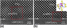
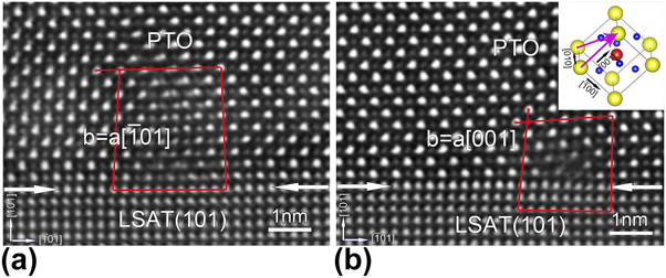
To accurately analyze the Burgers vectors and display the structural details of the interfacial MDs, the atomic scale high-resolution HAADF-STEM images corresponding to two white boxes labeled as “1” and “2” in Fig. 3(a) are obtained which are imaged along the in-plane [010] direction of LSAT, as shown in Figs. 4(a) and 4(b), respectively. As shown in Fig. 4(a), the dislocation core is very sharp, implying that the dislocation is observed in an edge-on condition, so this dislocation might possess a [010] line direction. By drawing a Burgers circuit surrounding this dislocation core, the Burgers vector b is determined to be  $a\left[ {\bar{1}01} \right]$. As mentioned above, MDs usually have perfect Burgers vectors a〈100〉 and a〈110〉 in perovskite thin films.Reference Suzuki, Nishi and Fujimoto16–Reference Qin, Jia, Urban, Hao and Xi19 Thus, in Fig. 4(a), the dislocation has a perfect Burgers vector of
 $a\left[ {\bar{1}01} \right]$ and a dislocation line of [010] direction, which indicated that the type I MDs are pure edge dislocations. Similarly, the Burgers vector of the type II MD can be determined as a[001] by drawing a Burgers circuit as shown in Fig. 4(b). However, the Burgers vector obtained from the [010] direction could not be a real vector since the dislocations might be of mixed type. This Burgers vector of b = a[001] is possibly a projected component of a perfect Burgers vector on (010) plane. Based on this consideration, the perfect Burgers vector of this MD in Fig. 4(b) might be either
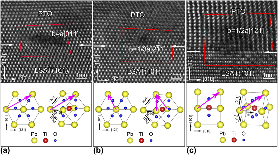
 $a\left[ {0\bar{1}1} \right]$ or a[001], as illustrated (pink arrows) in the inset, which are two common perfect Burgers vectors in perovskite thin films. Furthermore, the dislocation core is a little blurred, which is likely because this image is obtained in a non-edge-on condition. Thus, the dislocation line of type II MDs in Fig. 3(a) is probably not along the [010] direction. Combined with the plane-view TEM images in Fig. 2, it is inferred that dislocation line of the type II MDs might be along 〈111〉 directions. Thus, the atomic scale HAADF-STEM images taken along in-plane 〈111〉 directions of LSAT should be performed as well. Figures 5(a) and 5(b) are atomic scale high-magnification HAADF-STEM images of MDs taken along the in-plane
 $\left[ {\bar{1}\bar{1}1} \right]$ direction of LSAT. By drawing Burgers circuits, the Burgers vectors is determined as a[011] and
 ${1 / {3a\left[ {2\bar{1}1} \right]}}$, respectively. In Fig. 5(a), the MD with a projected component b = a[011] on
 $\left( {\bar{1}\bar{1}1} \right)$ plane has only one perfect Burgers vector of b = a[011], as illustrated in the bottom schematics of Fig. 5(a). However, the MD in Fig. 5(b) with a projected component
 $b = {1 / {3a\left[ {2\bar{1}1} \right]}}$ on
 $\left( {\bar{1}\bar{1}1} \right)$ plane has two possible perfect Burgers vectors, as illustrated in the bottom schematics of Fig. 5(b):
 ${1 / {3a\left[ {2\bar{1}1} \right]}}$ is denoted by a pink arrow in the left projected unit cell model viewed along the
 $\left[ {\bar{1}\bar{1}1} \right]$ direction of LSAT, and two possible perfect Burgers vectors of a[100] and
 $a\left[ {0\bar{1}1} \right]$ are distinguished in the right 3D unit cell model, which have the projected component
 ${1 / {3a\left[ {2\bar{1}1} \right]}}$ on
 $\left( {\bar{1}\bar{1}1} \right)$ plane. To distinguish these two kinds of dislocations with perfect Burgers vectors of a[100] and
 $a\left[ {0\bar{1}1} \right]$, the atomic scale HAADF-STEM imaging of the dislocation structure along the in-plane
 $\left[ {\bar{1}01} \right]$ direction is performed. Along the
 $\left[ {\bar{1}01} \right]$ direction, the former has a projected component b = 1/2a[101], while the latter has a projected component b = 1/2a[121]. Experimentally, many MDs with projected Burgers vector of b = 1/2a[121] are observed along the
 $\left[ {\bar{1}01} \right]$ direction, one of which is shown in Fig. 5(c). It is noteworthy that MDs with projected Burgers vector of b = 1/2a[101] are not observed. Furthermore, the MD with a projected component b = 1/2a[121] from the
 $\left[ {\bar{1}01} \right]$ direction has only one perfect Burgers vector of b = a[011], as illustrated in the bottom schematics of Fig. 5(c). Thus, the perfect Burgers vector of the MD in Fig. 5(b) is not a[100], but
 $a\left[ {0\bar{1}1} \right]$. Besides, the dislocation core in Fig. 5(b) is very sharp, indicating that the dislocation is imaged in an edge-on condition. As a result, the dislocation line of the dislocations with a perfect Burgers vector of
 $a\left[ {0\bar{1}1} \right]$ might be along the observed direction of
 $\left[ {\bar{1}\bar{1}1} \right]$, while the dislocation core in Fig. 5(a) looks blurred, indicating that
 $\left[ {\bar{1}\bar{1}1} \right]$ is not the dislocation line direction of the dislocation with Burgers vector of a[011]. According to the dislocation line patterns in Fig. 2(a), we propose that the MD with perfect Burgers vector of a[011] should have the dislocation line along the
 $\left[ {\bar{1}11} \right]$ direction.
High-resolution HAADF-STEM images taken along the [010] direction of LSAT showing two types of dislocations corresponding to the white rectangular boxes labeled as “1” and “2” in Fig. 3(a). (a) The type I MD with Burgers vector of  $b = a\left[ {\bar{1}01} \right]$. (b) The type II MD with Burgers vector of b = a[001]. Note that the dislocation core is blurred due to non-edge-on effect.
(a) and (b) High-resolution HAADF-STEM images of MDs in Figs. 4(a) and 4(b) taken along the  $\left[ {\bar{1}\bar{1}1} \right]$ direction of LSAT. (c) High-resolution HAADF-STEM image of MD taken along the [010] direction of LSAT. The bottom schematic diagrams illustrate the possible Burgers vectors.
III. DISCUSSION
A. MD formation mechanisms in the PTO/LSAT(101) film system
For the ferroelectric PTO/LSAT(101) thin film system at room temperature, the lattice mismatches along in-plane [010] and  $\left[ {\bar{1}01} \right]$ directions are −0.8% and −4.1%, respectively, which indicates that it has a large lattice mismatch along the
 $\left[ {\bar{1}01} \right]$ direction.Reference Feng, Tang, Ma, Zhu, Zou, Han, Ma and Ma25 However, taking into account the lattice expansion of PTO and LSAT at deposition temperature of 700 °C, the lattice mismatch values can be calculated to be approximately −1.85% along both in-plane [010] and
 $\left[ {\bar{1}01} \right]$ directions.Reference Shirane, Hoshino and Suzuki35,Reference Chakoumakos, Schlom, Urbanik and Luine36 To offset the misfit difference, the formation of either domains or MDs or both is believed to be a main mechanism depending on the film system itself. In the present study, formation of high-density MDs should be a main contributor to relieve the misfit strains.Reference Feng, Tang, Ma, Zhu, Zou, Han, Ma and Ma25
As mentioned above, MDs in PTO/LSAT(101) thin films have Burgers vectors of  $a\left[ {\bar{1}01} \right]$, a[011], and
 $a\left[ {0\bar{1}1} \right]$, whose line directions are along [010],
 $\left[ {\bar{1}11} \right]$, and
 $\left[ {\bar{1}\bar{1}1} \right]$, respectively. Dislocation with Burgers vector of
 $a\left[ {\bar{1}01} \right]$ is a pure edge dislocation, while the rest are mixed dislocations. As reported previously, MDs in perovskite film systems could mainly originate from the film by gliding, climbing, dislocation reaction, or nucleating during the beginning of film growth.Reference Tang, Zhu, Liu, Wang and Ma14–Reference Zhu, Ma, Li, Lu, Chen and Yang17,Reference Tang, Zhu, Meng, Zhang and Ma20,Reference Xu, Tang, Zhu, Liu, Li, Zhang and Ma23 For 〈111〉 MDs (the dislocation lines is along
 $\left[ {\bar{1}11} \right]$ and
 $\left[ {\bar{1}\bar{1}1} \right]$) in this PTO/LSAT(101) thin film system, they should be formed through gliding. Two reasons should be taken into account to interpret this phenomenon. On the one hand, dislocation movements by gliding may form a projected Burgers vector b of
 ${1 / {3a\langle 2\bar{1}1\rangle }}$, while the dislocation movement by climbing leads to a projected Burgers vector b of a〈110〉 when observed along dislocation line directions of 〈111〉.Reference Tang, Zhu, Meng, Zhang and Ma20 On the other hand, it is generally believed that gliding is easier than climbing because of a lower driving force needed. For [010] MDs (the dislocation line is along [010]), the direction of Burgers vector
 $b = a\left[ {\bar{1}01} \right]$ is along the in-plane
 $\left[ {\bar{1}01} \right]$ direction of LSAT, so the slip plane for this MDs is parallel to the PTO/LSAT(101) interface. Based on this consideration, gliding is impossible to result in [010] MDs. Besides, dislocation formation during the deposition of films occurs only when the lattice mismatch is very large. Formation of [010] MDs is almost impossible during film deposition because the lattice misfit is relatively small (about −1.8%) at the deposition temperature of 700 °C.Reference Xu, Tang, Zhu, Liu, Li, Zhang and Ma23 Thus, climbing is probably the only way to form the [010] MDs. Meanwhile, formation of 〈111〉 and [010] MDs might occur at the stage of cooling. Configuration and forming mechanisms of MDs in the present film system agree well with those of our previous study in (110)-oriented Nd0.45Sr0.55MnO3 film,Reference Tang, Zhu, Meng, Zhang and Ma20 which indicates that formation mechanism of MDs has universal relevance for {110}-oriented perovskite thin films.
Why are there a small number of [010] MDs? It can be understood from two aspects. One is that [010] MDs formed through climbing need a larger driving force and more energy than gliding. Climbing generally occurs with thermal diffusion at high temperature.Reference Langjahr, Lange, Wagner and Ruhle37 This is the reason why we have observed a low density of [010] MDs. The other lies in the difference in strain energy. According to the dislocation theory, dislocation strain energy E d of the mixed dislocation per unit length can be calculated via the following formulasReference Jain, Harker and Cowley12:
 $${E_{\rm{d}}} = {{G{b^2}\left( {1 - \nu \;{{\cos }^2}\;\beta } \right)} \over {4\pi \left( {1 - \nu } \right)}}\ln {{2{\rho _{\rm{c}}}h} \over b}\quad ,$$
where G is the shear modulus of elasticity, b is the norm of the Burgers vector, ν is the Poisson’s ratio, h is the thickness of the film, ρc is the dislocation core parameter, and β is the intersection angle between dislocation line and Burgers vector. For [010] or 〈111〉 MDs in PTO thin films, only β is different. For the former β = 90°, and for the latter 0° < β < 90°. It can be deduced that the dislocation strain energy of [010] MDs is larger than that of the 〈111〉 MDs, which prevents the formation of a large amount [010] MDs in the present thin film system.
B. Misfit strain relaxation of the PTO/LSAT(101) film systems
The importance of MD is well known, through which misfit strain is relaxed in perovskite thin films. In the present thin film system, two types of MDs, named [010] MDs and 〈111〉 MDs, are observed. Both of these MDs have the Burgers vector of a〈110〉. Since the two types of MDs have different characteristics, the misfit strain relaxation contributed by MDs should be discussed separately. First, for [010] MDs, the Burgers vector of  $b = a\left[ {\bar{1}01} \right]$ is along the in-plane
 $\left[ {\bar{1}01} \right]$ direction, which is parallel to the PTO/LSAT(101) interface and has no perpendicular component along the interface. Besides, [010] MDs have no components along the in-plane [010] direction. Thus, [010] MDs can only relax the in-plane
 $\left[ {\bar{1}01} \right]$ directional misfit strain and cannot relax the in-plane [010] directional misfit strain. Next, for 〈111〉 MDs, misfit strain relaxation is very complicated because Burgers vectors of b = a[011] or
 $b = a\left[ {0\bar{1}1} \right]$ are inclined to the interface. Taking the MD with Burgers vector of b = a[011] and line direction of
 $\left[ {\bar{1}11} \right]$ for example, to better understand its contributions to the misfit strain relaxation, the perfect Burgers vector of b = a[011] should be decomposed into several components, as illustrated in Fig. 6. The red arrow denotes the perfect Burgers vector of b = a[011], which is decomposed into two components (denoted by blue arrows) according to the following formula:
 $$a\left[ {011} \right] = {1 / {2a\left[ {\bar{1}01} \right] + {1 / {2a\left[ {121} \right]}}}}\quad ,$$
where  ${1 / {2a\left[ {\bar{1}01} \right]}}$ is parallel to the PTO/LSAT(101) interface, which relaxes the in-plane
 $\left[ {\bar{1}01} \right]$ directional misfit strain. The 1/2a[121] component can be further decomposed into two components (denoted by yellow arrows) as shown in the following formula:
 $${1 / {2a\left[ {121} \right]}} = a\left[ {010} \right] + {1 / {2a}}\left[ {101} \right]\quad .$$
A schematic diagram showing the decomposition of Burgers vector. The red arrow denotes perfect Burgers vector; the blue arrows denote the in-plane  $\left[ {\bar{1}01} \right]$ directional component and projection component in (010) plane, which can be further decomposed as shown by yellow arrows.
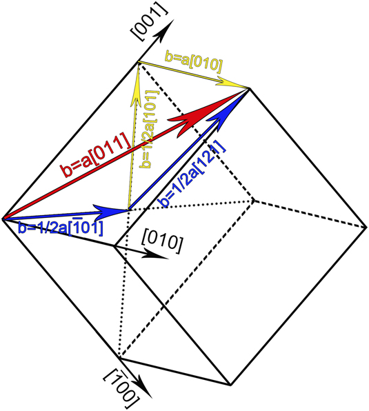
The a[010] component is also parallel to the PTO/LSAT(101) interface and can relax the in-plane [010] directional misfit strain, while the 1/2a[101] component is perpendicular to the PTO/LSAT(101) interface, which could relax shear strains resulting from large lattice rotations between the neighboring 90° domains.Reference Xu, Tang, Zhu, Liu, Li, Zhang and Ma23 Thus, 〈111〉 MDs not only relax the misfit strains of both in-plane  $\left[ {\bar{1}01} \right]$ and [010] directions, but also relax the shear strain in neighboring domains.
As mentioned above, the lattice mismatch along the in-plane  $\left[ {\bar{1}01} \right]$ direction can be calculated to be −4.1%. Thus, the theoretical spacing (S) of 〈111〉 MDs along
 $\left[ {\bar{1}01} \right]$ can be derived from the following equationReference Suzuki, Nishi and Fujimoto16:
 $$S = {b \over f}\quad ,$$
where b is the magnitude of projected Burgers vectors on (010) plane of 〈111〉 MDs and f is the lattice mismatch value between the stress-free thin film and substrate. Thus, the theoretical spacing of 〈111〉 MDs along  $\left[ {\bar{1}01} \right]$ is about 7 nm. However, the average dislocation spacing (D) between adjacent dislocations is measured to be approximately 10.9 nm, which is obtained statistically from numerous cross-sectional high-resolution HAADF-STEM images. The contributed extent (R) of lattice misfit relaxation along
 $\left[ {\bar{1}01} \right]$ only by the formation of interfacial MDs can be calculated according to the following equationReference Suzuki, Nishi and Fujimoto16:
 $$R = {{{b / f}} \over D}\quad .$$
R is calculated to be about 64%, which means that only about 64% misfit strain is relieved by the formation of interfacial MDs. In the present PTO/LSAT(101) film system, stripe 90° c 1/c 2 domains and some 90° a/c domains are observed in the PTO films as shown in Fig. 1. As proposed previously, formation of stripe 90° c 1/c 2 domains can hardly relax the in-plane  $\left[ {\bar{1}01} \right]$ directional misfit strain.Reference Feng, Tang, Ma, Zhu, Zou, Han, Ma and Ma25 Instead, the residual misfit strain could be relaxed by the formation of 90° a/c domains.
Geometrically, 〈111〉 MDs with an average dislocation spacing of 10.9 nm along the $\left[ {\bar{1}01} \right]$ direction also have an average dislocation spacing of 7.8 nm along the in-plane [010] direction, which can relax the in-plane [010] directional misfit strain up to 5.0%. However, at room temperature, the lattice mismatch calculated along the in-plane [010] direction is only about −0.8%. So the tensile stress occurs along the in-plane [010] direction in PTO films, which promotes the nucleation of a domains to compensate the tensile strain field in the [010] direction. This is the reason why there are some 90° a/c domains in this film system. As discussed above, both the interfacial MDs and 90° a/c domains contribute to the misfit strain relaxation along both the in-plane
 $\left[ {\bar{1}01} \right]$ and [010] directions, and also they remarkably interact, which indicates a big difference in strain relaxation mechanisms between the (101)- and (001)-oriented ferroelectric PTO films. Furthermore, the strain relaxation behavior and the formation of a/c domains in (101)-oriented ferroelectric PTO films may also work for the (101)-oriented tetragonal Pb(Zr, Ti)O3 thin films.
IV. CONCLUSION
In this study, we investigate the interfacial MDs and misfit strain relaxation behavior of (101)-oriented ferroelectric PTO epitaxial thin films grown on LSAT(101) substrates using TEM approaches. We find two types of MDs at the interface, which have the majority of contribution to the misfit strain relaxation. One is formed by gliding with the Burgers vectors of a[011] or  $a\left[ {0\bar{1}1} \right]$ and line direction of 〈111〉, which not only simultaneously relaxes the misfit strain of both in-plane
 $\left[ {\bar{1}01} \right]$ and [010] directions, but also relaxes the shear strain in adjacent domains. The other is formed by climbing with the Burgers vectors of
 $a\left[ {\bar{1}01} \right]$ and line direction of [010], which only relaxes the misfit strain of
 $\left[ {\bar{1}01} \right]$ direction. The residual misfit strains are relaxed by the formation of 90° a/c domains. These results may shed some light on the understanding of asymmetric strain relaxation in (101)-oriented perovskite thin films and provide useful information for the growth of the (101)-oriented perovskite thin films.
V. EXPERIMENTAL
The PTO thin films were deposited on single-crystal LSAT(101) substrates by pulsed laser deposition (PLD), using a Coherent ComPexPRO 201FKrF (λ = 248 nm) excimer laser. A sintered PTO target (3 mol% Pb-enriched) was used. Before deposition, the substrate was preheated to 800 °C for 5 min to clean the substrate surface and then cooled down to film-growing temperature. During deposition, an oxygen pressure of 10 Pa, laser energy density of 2 J/cm2, growing temperature of 700 °C, and a repetition rate of 4 Hz were used. After deposition, the film was annealed at 700 °C for 5 min in an oxygen pressure of 3 × 10⁴ Pa and then cooled down to room temperature at a rate of 5 °C/min.
Cross-sectional and plane-view TEM samples for TEM and STEM observations were prepared by slicing, mechanical grinding, dimpling, and finally ion milling by Gatan 691 PIPS (Gatan Inc., Pleasanton, California). Before ion milling, the samples were dimpled down to about 10 μm. The final voltage of milling was less than 0.5 kV for 10 min to reduce the ion beam damage. Plane-view TEM samples were grinded, dimpled, and finally ion-milled only from the substrate side. Bright-field and dark-field TEM images were recorded by Tecnai G2 F30 transmission electron microscope (FEI, Hillsboro, Oregon). All HAADF-STEM images were acquired by aberration-corrected (scanning) transmission electron microscope (Titan G2 60-300 kV microscope (FEI) equipped with double aberration correctors from CEOS and a monochromator operating at 300 kV). Large-scale strain field was extracted by using GPA, carried out using Gatan Digital Micrograph software (Gatan Inc.).
ACKNOWLEDGMENTS
This work is supported by the National Natural Science Foundation of China (Nos. 51571197, 51501194, and 51671194), National Basic Research Program of China (2014CB921002), and the Key Research Program of Frontier Sciences CAS (QYZDJ-SSW-JSC010). Y.L.T. acknowledges the IMR SYNL-T.S. Kê Research Fellowship and the Youth Innovation Promotion Association CAS (No. 2016177). The authors are grateful to Mr. B. Wu and Mr. L.X. Yang for their technical support on the Titan platform of G2 60-300 kV aberration-corrected scanning transmission electron microscope.