





%20--%3e%3c!DOCTYPE%20svg%20PUBLIC%20'-//W3C//DTD%20SVG%201.0//EN'%20'http://www.w3.org/TR/2001/REC-SVG-20010904/DTD/svg10.dtd'%3e%3csvg%20version='1.0'%20id='Layer_1'%20xmlns='http://www.w3.org/2000/svg'%20xmlns:xlink='http://www.w3.org/1999/xlink'%20x='0px'%20y='0px'%20width='64px'%20height='64px'%20viewBox='5.5%20-3.5%2064%2064'%20enable-background='new%205.5%20-3.5%2064%2064'%20xml:space='preserve'%3e%3cg%3e%3ccircle%20fill='%23FFFFFF'%20fill-opacity='0'%20cx='37.785'%20cy='28.501'%20r='28.836'/%3e%3cpath%20fill='%23595959'%20d='M37.441-3.5c8.951,0,16.572,3.125,22.857,9.372c3.008,3.009,5.295,6.448,6.857,10.314%20c1.561,3.867,2.344,7.971,2.344,12.314c0,4.381-0.773,8.486-2.314,12.313c-1.543,3.828-3.82,7.21-6.828,10.143%20c-3.123,3.085-6.666,5.448-10.629,7.086c-3.961,1.638-8.057,2.457-12.285,2.457s-8.276-0.808-12.143-2.429%20c-3.866-1.618-7.333-3.961-10.4-7.027c-3.067-3.066-5.4-6.524-7-10.372S5.5,32.767,5.5,28.5c0-4.229,0.809-8.295,2.428-12.2%20c1.619-3.905,3.972-7.4,7.057-10.486C21.08-0.394,28.565-3.5,37.441-3.5z%20M37.557,2.272c-7.314,0-13.467,2.553-18.458,7.657%20c-2.515,2.553-4.448,5.419-5.8,8.6c-1.354,3.181-2.029,6.505-2.029,9.972c0,3.429,0.675,6.734,2.029,9.913%20c1.353,3.183,3.285,6.021,5.8,8.516c2.514,2.496,5.351,4.399,8.515,5.715c3.161,1.314,6.476,1.971,9.943,1.971%20c3.428,0,6.75-0.665,9.973-1.999c3.219-1.335,6.121-3.257,8.713-5.771c4.99-4.876,7.484-10.99,7.484-18.344%20c0-3.543-0.648-6.895-1.943-10.057c-1.293-3.162-3.18-5.98-5.654-8.458C50.984,4.844,44.795,2.272,37.557,2.272z%20M37.156,23.187%20l-4.287,2.229c-0.458-0.951-1.019-1.619-1.685-2c-0.667-0.38-1.286-0.571-1.858-0.571c-2.856,0-4.286,1.885-4.286,5.657%20c0,1.714,0.362,3.084,1.085,4.113c0.724,1.029,1.791,1.544,3.201,1.544c1.867,0,3.181-0.915,3.944-2.743l3.942,2%20c-0.838,1.563-2,2.791-3.486,3.686c-1.484,0.896-3.123,1.343-4.914,1.343c-2.857,0-5.163-0.875-6.915-2.629%20c-1.752-1.752-2.628-4.19-2.628-7.313c0-3.048,0.886-5.466,2.657-7.257c1.771-1.79,4.009-2.686,6.715-2.686%20C32.604,18.558,35.441,20.101,37.156,23.187z%20M55.613,23.187l-4.229,2.229c-0.457-0.951-1.02-1.619-1.686-2%20c-0.668-0.38-1.307-0.571-1.914-0.571c-2.857,0-4.287,1.885-4.287,5.657c0,1.714,0.363,3.084,1.086,4.113%20c0.723,1.029,1.789,1.544,3.201,1.544c1.865,0,3.18-0.915,3.941-2.743l4,2c-0.875,1.563-2.057,2.791-3.541,3.686%20c-1.486,0.896-3.105,1.343-4.857,1.343c-2.896,0-5.209-0.875-6.941-2.629c-1.736-1.752-2.602-4.19-2.602-7.313%20c0-3.048,0.885-5.466,2.658-7.257c1.77-1.79,4.008-2.686,6.713-2.686C51.117,18.558,53.938,20.101,55.613,23.187z'/%3e%3c/g%3e%3c/svg%3e)
%20--%3e%3c!DOCTYPE%20svg%20PUBLIC%20'-//W3C//DTD%20SVG%201.0//EN'%20'http://www.w3.org/TR/2001/REC-SVG-20010904/DTD/svg10.dtd'%3e%3csvg%20version='1.0'%20id='Layer_1'%20xmlns='http://www.w3.org/2000/svg'%20xmlns:xlink='http://www.w3.org/1999/xlink'%20x='0px'%20y='0px'%20width='64px'%20height='64px'%20viewBox='5.5%20-3.5%2064%2064'%20enable-background='new%205.5%20-3.5%2064%2064'%20xml:space='preserve'%3e%3cg%3e%3ccircle%20fill='%23FFFFFF'%20fill-opacity='0'%20cx='37.637'%20cy='28.806'%20r='28.276'/%3e%3cg%3e%3cpath%20fill='%23595959'%20d='M37.443-3.5c8.988,0,16.57,3.085,22.742,9.257C66.393,11.967,69.5,19.548,69.5,28.5c0,8.991-3.049,16.476-9.145,22.456%20C53.879,57.319,46.242,60.5,37.443,60.5c-8.649,0-16.153-3.144-22.514-9.43C8.644,44.784,5.5,37.262,5.5,28.5%20c0-8.761,3.144-16.342,9.429-22.742C21.101-0.415,28.604-3.5,37.443-3.5z%20M37.557,2.272c-7.276,0-13.428,2.553-18.457,7.657%20c-5.22,5.334-7.829,11.525-7.829,18.572c0,7.086,2.59,13.22,7.77,18.398c5.181,5.182,11.352,7.771,18.514,7.771%20c7.123,0,13.334-2.607,18.629-7.828c5.029-4.838,7.543-10.952,7.543-18.343c0-7.276-2.553-13.465-7.656-18.571%20C50.967,4.824,44.795,2.272,37.557,2.272z%20M46.129,20.557v13.085h-3.656v15.542h-9.944V33.643h-3.656V20.557%20c0-0.572,0.2-1.057,0.599-1.457c0.401-0.399,0.887-0.6,1.457-0.6h13.144c0.533,0,1.01,0.2,1.428,0.6%20C45.918,19.5,46.129,19.986,46.129,20.557z%20M33.042,12.329c0-3.008,1.485-4.514,4.458-4.514s4.457,1.504,4.457,4.514%20c0,2.971-1.486,4.457-4.457,4.457S33.042,15.3,33.042,12.329z'/%3e%3c/g%3e%3c/g%3e%3c/svg%3e)
1. Introduction
When a supersonic flow passes over symmetric wedges, a shock interaction/reflection occurs due to the flow turning. The shock reflection can be either a Mach reflection (MR) or a regular reflection (RR), depending on the flow parameters and wedge geometry. Figure 1 depicts the possible shock reflections between the maximum and minimum values of the height of the trailing edge from the symmetry line (Ht) (Li & Ben-Dor Reference Li and Ben-Dor1997). The Ht value depends on the wedge length  $(w)$, wedge angle
 $(\theta )$ and the height of the wedge leading edge from the symmetry line
 $(H)$, as shown in figure 1(a,b). The wedge length is also an essential parameter, and based on the non-dimensionalised wedge length (
 $w/H$), we can classify wedges as long or short. As depicted in figure 2(a), most research on wedge flow focuses on long wedges where the expansion fan from the trailing edge does not interact with the incident shock wave. As shown in figure 2(b), the expansion fan will interact with the incident shock wave in the short wedges. Due to expansion fan interaction, the incident shock angle in short wedges decreases, and the shock curves continuously from the point where the leading expansion characteristic meets the shock wave to the triple/reflection point.
 ${\rm Ht}_{min}$ and
 ${\rm Ht}_{max}$ for (a) MR and (b) RR.

Schematic diagram for (a) long wedge and (b) short wedge.

The curvature of the incident shock essentially depends on the extent of the expansion fan interaction. Consequently, the incident shock angle at the point of reflection will depend not only on the wedge angle and the flow Mach number but also on the  $w/H$ ratio. Any attempt to predict the shock transitions on short wedges must hence incorporate an accurate model of the incident shock curvature resulting from its interaction with the expansion fan.
1.1. Previous works in shockwave – expansion fan interaction
The interaction of shock waves and expansion waves in one-dimensional flows is the subject of several investigations in high-speed flows (Emanuel Reference Emanuel2001). A comprehensive description of the interaction of shock waves, expansion waves and contact surfaces, mainly in shock tube flows, can be seen in the work of Glass (Reference Glass1991). Li & Ben-Dor (Reference Li and Ben-Dor1996) conducted a study on the interaction between expansion fans and shock waves in symmetric wedge flows. In this work, Li & Ben-Dor (Reference Li and Ben-Dor1996) developed an analytical model to obtain the curvature of the shock wave due to its interaction with the centred expansion wave of the opposite family by using a second-order polynomial. The experimental and numerical validations of this analytical model (Nel & Skews Reference Nel and Skews2019) revealed that while the model prediction was accurate for small interactions, it could not predict shock curvature for stronger interactions. Vuillon, Zeitoun & Ben-Dor (Reference Vuillon, Zeitoun and Ben-Dor1995) numerically studied the  ${\rm RR}\leftrightarrow {\rm MR}$ transitions in the dual solution domain and found that the Mach stem height reduced linearly as the wedge trailing-edge height is increased. From numerical simulations, they also found a value of the trailing edge height
 ${\rm Ht}_{tr}$ in between
 ${\rm Ht}_{max}$ and
 ${\rm Ht}_{min}$. They concluded that when the Ht value is in between
 ${\rm Ht}_{tr}$ and
 ${\rm Ht}_{max}$, the stable configurations were regular reflections and the numerical attempts to establish Mach reflection configurations in this range failed. However, later, Li & Ben-Dor (Reference Li and Ben-Dor1997) found out that the equation used by Vuillon et al. (Reference Vuillon, Zeitoun and Ben-Dor1995) to calculate
 ${\rm Ht}_{max}$ was wrong due to an incorrect assumption and corrected this. Moreover, Vuillon et al. (Reference Vuillon, Zeitoun and Ben-Dor1995) have not considered the transition phenomenon when the expansion fan starts interacting with the incident shock which is the context of the present study. In another study by Hillier (Reference Hillier2007) on the shock-wave/expansion-wave interaction and the transition between regular and Mach reflections, analytical and numerical simulations were carried out to investigate the inviscid interactions of an expansion wave with an incident shock wave of the opposite family. The study was to stabilise a Mach reflection in a parallel duct for different flow conditions. Most of the analytical methods developed in shock reflections focused on predicting the MR configuration and the Mach stem height, a finite length scale in an MR in long wedges (Azevedo & Liu Reference Azevedo and Liu1993; Li & Ben-Dor Reference Li and Ben-Dor1997; Mouton & Hornung Reference Mouton and Hornung2007). In these models, the slip line, which originates from the triple point in a Mach reflection, was assumed to be a straight line. Later, the refinement of the slip line curvature was carried out (Gao & Wu Reference Gao and Wu2010; Bai & Wu Reference Bai and Wu2017) resulting in a better Mach stem prediction, as they considered the expansion waves generated over the slip line and its interaction with the transmitted expansion waves through the reflected shock. Further, numerical studies of a shock reflection in the presence of an upstream expansion wave and a downstream shock wave for two-dimensional flows by Yao, Li & Wu (Reference Yao, Li and Wu2013) reported that the expansion fan delayed the
 ${\rm RR}\leftrightarrow {\rm MR}$ transition at lower Mach numbers (
 $M = 2\unicode{x2013}3.5$) and expedited it at higher Mach numbers.
The analytical models discussed above were all for the interaction of the shock wave with the opposite (either right-running or left-running) family of expansion waves. In contrast, the incident shock in short wedges is curved as a result of the prolonged interaction of the expansion wave of the same family. The study of this type of interaction is significant because the  ${\rm RR}\leftrightarrow {\rm MR}$ transition may only depend on the incident shock angle at the reflection point, which is determined by the shock curvature caused by the interaction. As a result, it is critical to identify the parameters that govern the shock angle at the reflection point, as well as the changes in transition criteria that occur when these parameters change.
Bai (Reference Bai2023) conducted the first analytical and computational studies of the incident shock interaction with the wedge trailing-edge expansion fan of the same family. The shock reflection transitions were quantified for different values of g (wedge trailing-edge height to inlet height (Ht/ $H$), as shown in figure 2b). Bai (Reference Bai2023) developed an analytical model to predict incident shock wave curvature due to expansion wave interaction. The model is based on the interaction of C
 $-$ waves generated from the wedge trailing edge and neglects the reflected C+ characteristics from the interaction point. For short wedges, the shift in the detachment and von Neumann transition lines for various g values were also constructed by Bai (Reference Bai2023). Apart from that, the results for Mach numbers less than two were not provided (refer to figure 6 of Bai Reference Bai2023). For a given
 $M$ and
 $\theta _w$ value, the
 $g^{(D)}$ value or
 $g^{(N)}$ value is found out from the above-mentioned plot of Bai (Reference Bai2023) and then this value is compared with the calculated
 $g$ value to determine whether the shock reflection is an MR or an RR. Although the analytical method is very fast, ignoring the C+ waves in the model assumption may lead to small errors at higher wedge angles especially close to the no-reflection boundary.
In addition to the model of Bai (Reference Bai2023), there is another model that approximates the interaction between shock waves and expansion waves. In 1952, Moeckel (Reference Moeckel1952) introduced a method for determining the shockwave curvature in a non-uniform flow field, particularly for an upstream flow characterised by a Mach number that changes continuously. Moeckel (Reference Moeckel1952) elaborated on the diverse possible interactions that can occur within the flow field and presented analytical frameworks for modelling the flow field, encompassing the interaction between the expansion fan and the shock wave (i.e. either upstream or downstream of the flow). Chisnell (Reference Chisnell1955) studied the interaction of a shock wave with a weak contact discontinuity and gave a first-order relationship between change in shock strength and change in density across the discontinuity, which is integrated to give the shock strength as a function of the initial density of the non-uniform medium in closed form. Subsequently, Whitham (Reference Whitham1958) demonstrated that the works of Moeckel (Reference Moeckel1952) regarding the interaction of an oblique shock wave with a shear layer in steady supersonic flow and Chisnell (Reference Chisnell1955) regarding the propagation of a shock wave down a non-uniform tube are necessarily the same and named it as the Moeckel–Chisnell (MC) method. In the present work, we have applied the MC method to study the shock wave and expansion fan interaction.
In the MC method, the interaction between the expansion fan and the shockwave presents a formidable challenge, rendering it as computationally intensive as that of the method of characteristics (MoC). The inclusion of upstream interaction effects in the MC method for computing shockwave curvature does not result in substantial additional complexity. However, Moeckel (Reference Moeckel1952) showed that effective incorporation of downstream interactions of the expansion fan requires an iterative approach akin to that of MoC. Following this, Moeckel (Reference Moeckel1952) demonstrated that the shockwave curvature can be calculated with minimal error if the influence of reflected first-order waves caused by the downstream expansion fan interacting with the shockwave is ignored. This approximation, i.e. neglecting the first-order reflected waves, is used in developing the shockwave expansion fan interaction model in the present work along with a more precise MoC model. Similar assumptions were successfully used in the development and application of the shock-expansion theory. The magnitude of the error associated with this approximation grows with the increase in wedge angle and Mach number. In terms of error, the Mach number has a more significant impact than the wedge angle. The application of the approximations above in constructing a model for the current study is discussed in § 2.
In the current study, a semi-analytical model is developed using MoC equations and numerical techniques (henceforth referred to as the MoC method throughout this paper), which includes the reflected C+ waves from the incident shock, in contrast to the model of Bai (Reference Bai2023), which only considers C $-$ waves to determine the incident shock curvature and shock angle at the reflection point. This MoC model is used to study the prolonged interaction of an expansion wave with an incident shock wave of the same family to predict the shock wave curvature. The MoC model developed is compared with the model of Bai (Reference Bai2023) and the MC method. Investigations on the shock transition in symmetric short wedges, particularly the shift in the dual solution domain, are also incorporated. We have used the
 $w/H$ ratio as the independent parameter for studying the transition for a range of Mach numbers from 1 to 5, which led to three distinct classifications for the shock transitions in short wedges, in dual solution domains.
The MoC model is compared with a well-validated in-house computational fluid dynamics (CFD) model, which is an inviscid, two-dimensional (2-D), structured finite volume solver with a fifth-order WENO scheme (Paramanantham, Janakiram & Gopalapillai Reference Paramanantham, Janakiram and Gopalapillai2022). The  ${\rm RR}\leftrightarrow {\rm MR}$ transition lines are expected to be altered by the interactions of the expansion wave with the shock wave due to the small wedge lengths. The reflections above and below the transition lines for short wedges are verified by comparing them with shadowgraph images from experiments.
2. Shock wave expansion fan interaction – analytical modelling
The MC method and MoC are employed to model the shockwave/expansion fan interaction, and the MoC results are compared to validate the accuracy of the MC model. In this section, we will examine the development of the MoC and MC methods for shock expansion interaction.
2.1. Method of characteristics
The shock–expansion interaction is modelled with the MoC which is clearly explained by Zucrow & Hoffmann (Reference Zucrow and Hoffmann1977) for steady, two-dimensional rotational flow. The model assumptions are that the flow is steady, compressible, inviscid, two-dimensional (planar) and rotational as it is a curved shock. The entropy is constant only along the streamlines. The basic configuration of the incident shock–expansion fan interaction model is shown in figure 3. The characteristic and compatibility equations for two-dimensional, isentropic, rotational and supersonic flow are given in table 1. The details of the variables in table 1 and their implementation are explained in Appendix A in detail.
Shock–expansion fan interaction model using MoC.

Steady, two-dimensional, isentropic, rotational supersonic flow.

2.1.1. Interior points
The initial value line for the MoC is the first characteristic expansion line from the trailing edge (point D in figure 3), which terminates at the intersection of the incident shock wave and the first expansion line (point B). The solution algorithm is initiated by giving a small increment of flow turn angle downstream from point D. The flow properties at point D are determined using the Prandtl–Meyer relations. The C $-$ curve from point D and the C+ curve from point B intersect at point B1 as shown in figure 3. The rearward running streamline C
 $_o$ intersects the line DB (line connecting initial data points) at point S. The properties at point S are obtained by linear interpolation. Three distinct characteristic lines are intersecting at point B1 (viz. one streamline and two Mach lines). As shown in table 1, there are two compatibility equations valid along the streamline and one compatibility equation along each Mach line. The flow properties and location at point B1 are obtained by numerically solving the above-mentioned characteristic and compatibility equations from data points B and D, along with that for the streamline passing through point S.
2.1.2. Points on the curved shock
The curved shock is obtained by solving discrete points on the shock. Since MoC is not valid across the shock, the solution point at the shock curvature is obtained by iteratively computing the local pressure ratio across the shock. Post-shock properties are calculated with the local incoming Mach number and the assumed pressure ratio across the shock. These flow properties should satisfy the compatibility equation along the C $-$ curve originating from the interior point B1. The iterations stop when this condition is satisfied. The local shock angle is obtained, and the
 $x$ and
 $y$ coordinates of the curved shock are obtained by solving the characteristic equations. Subsequent points on the curved shock are obtained by incrementing the next flow turn angle at point D and repeating the above steps. One of the algorithms calculates the interior points in the flow field, while the other determines the discrete points along the shock curvature. Here,
 $\phi _2$ and
 $\theta _{eff}$ represent the shock angle and effective turn angle at the reflection point R, respectively, as shown in figure 3. The analytical model developed does not consider the possibility of Mach reflection and is valid only for regular reflection. The detailed algorithm is described in Appendix A.
2.2. Moeckel–Chisnell (MC) method
The MC method consists of finding the shockwave curvature due to the non-uniformities in the flow field. The current approach takes into account a straightforward interaction between expansion waves and shockwaves by disregarding any first-order or second-order reflected waves on the flow field. Figure 4 depicts a schematic of the interaction between the expansion fan and shockwave used in the current model. The locations upstream and downstream of the incident shock wave are denoted by 0 and 1, respectively. The expansion fan is partitioned into N waves in the present model, with Mach number and pressure variations following the Prandtl–Meyer relation. The naming convention for the flow field across the expansion waves is identical to that of the incident shockwave, as depicted in figure 4. The interaction point of the nth expansion wave with the shock wave is denoted as n, as shown in figure 4.
Schematic of shock expansion wave interaction for Moeckel–Chisnell method.

The flow field downstream of the shockwave in Region 1 is determined by applying the oblique shock relations described in (2.1)–(2.3). The expansion fan turn angle is assumed to be equivalent to the wedge angle.
 \begin{gather} \dfrac{p_1}{p_0} = \dfrac{2\gamma}{\gamma+1}M_0^2\sin^2{\phi} - \dfrac{\gamma - 1}{\gamma + 1}, \end{gather}
 \begin{gather} \tan \theta = \frac{M_0^2\sin{\phi}\cos{\phi} - \cot{\phi}}{1 + M_0^2 \left( \dfrac{\gamma + 1}{2} - \sin^2{\phi} \right)}, \end{gather}
 \begin{gather} M_1^2 = \dfrac{(\gamma+1)^2 M_0^4\sin^2{\phi} -4(M_0^2\sin^2{\phi}-1)(\gamma M_0^2\sin^2{\phi}+1)}{[2\gamma M_0^2\sin^2{\phi} - (\gamma-1)][(\gamma-1)M_0^2\sin^2{\phi}+2]}. \end{gather}
The incremental Prandtl–Meyer angle  $(\Delta \nu )$ of any expansion wave is therefore calculated by (2.4). The PM angle is used to compute the pressure and Mach number downstream of the expansion wave as given in (2.5)–(2.8).
 \begin{gather} \Delta \nu = \frac{\theta_w}{N}, \end{gather}
 \begin{gather} \nu_n = \Delta \nu*n + \nu(M_{n-1}), \end{gather}
 \begin{gather} \nu_n = \sqrt{\frac{\gamma+1}{\gamma-1}}\tan^{-1}{\sqrt{\frac{\gamma-1}{\gamma+1}(M^2_n-1)}} - \tan^{-1}{\sqrt{M^2_n-1}}. \end{gather}
The pressure  $(\,p_n)$ calculated from the Prandtl–Meyer relation is taken as the pressure at the interaction point of the expansion wave with the shock wave. This pressure is used to compute the shock wave angle using the oblique shock relation given in (2.9). According to the analysis by Moeckel (Reference Moeckel1952), the reflection of first-order waves resulting from the interaction between the expansion fan and the shockwave (shown as a dotted red line in figure 4) is negligible and thus disregarded in the model. This method simplifies the computation of the expansion waves downstream of the flow field because it does not interact with any other waves in the flow field.
 $$\begin{gather} \dfrac{p_n}{p_{n-1}} =\frac{\left(1 + \dfrac{\gamma-1}{2}M^2_{n-1}\right)^{{\gamma}/({\gamma+1})}}{\left(1 + \dfrac{\gamma-1}{2}M^2_n\right)^{{\gamma}/({\gamma+1})}}, \end{gather}$$
 $$\begin{gather}\theta_n = \theta_{n-1} - \Delta \nu*n , \end{gather}$$
 $$\begin{gather}\phi_n = \sin^{-1}\left[\frac{1}{M_0} \sqrt{\left[ \frac{\gamma+1}{2\gamma}\left(\frac{p_n}{p_0}-1\right)+1 \right]}\right]. \end{gather}$$
After determining the shock angle, the point of interaction between the shock wave and the expansion wave can be calculated using (2.10)–(2.12). The procedure is executed until the  $y$ coordinate becomes zero. This method gives the entire shock curvature with the expansion fan interaction, and works very well, though it has some approximate assumptions as discussed in the sections above. For this reason, the more accurate MoC method is used for constructing the transition lines as explained in the subsequent sections.
 $$\begin{gather} \frac{Y_{n-1} - Y_n}{X_{n-1} - X_n} =- \tan{\phi_n}, \end{gather}$$
 $$\begin{gather}\frac{Y_C - Y_n}{X_C - X_n} = \tan{(\theta_n + \mu_n)}, \end{gather}$$
 $$\begin{gather}\mu_n = \sin^{-1}{\frac{1}{M_n}}. \end{gather}$$
3. Shockwave expansion fan interaction – validation with CFD results
For the numerical simulations, a 2-D, inviscid, finite volume, high order shock capturing code is employed. To obtain high-order accuracy and capture the shockwaves without oscillations, the algorithm employs WENO reconstruction. Since the viscous effects are negligible, the inviscid simulations are adequate to explore the shock expansion interaction. The code uses the HLLC approximate Riemann solver for the flux calculation and  $4$th-order Runge–Kutta ordinary differential equation (ODE) solver to march in time. Further details regarding the numerical method can be found in the literature (Thara Reshma et al. Reference Thara Reshma, Vinoth, Rajesh and Ben-Dor2021; Paramanantham et al. Reference Paramanantham, Janakiram and Gopalapillai2022). The computational domain is illustrated in figure 5. The inlet of the domain is taken to be 60 mm. We maintain the wedge length at 20 mm. The domain measures 200 mm in length. Figure 5 further displays the boundary conditions used for the present numerical simulations. The domain is discretised with
 $650 \times 100$ cells in the
 $x$ and
 $y$ directions, respectively. The validation of the analytical model with CFD is carried out by superimposing the curved shock locus of the more accurate MoC results and the computational results, as shown in figure 6(a). It reveals that the MoC prediction agrees very well with the CFD results qualitatively. The same is done by varying the Mach number,
 $w/H$ ratio and the wedge angle. The Mach number versus the non-dimensional shock reflection distance (shown in figure 3) (
 $R/H$) for different
 $w/H$ ratios, obtained from analytical and CFD results, are plotted. Figure 6(b) shows one such plot of Mach number versus
 $R/H$ for the
 $w/H$ ratio 0.33 for different wedge angles. Similarly, the shock angle obtained at the reflection point using the MoC method is compared with that obtained in CFD, as shown in figure 7. It is seen that the maximum difference between the analytical and CFD results is less than 2 %.
Schematic of computational domain used for the present simulations.

(a) Superimposed image of MoC and computational result. (b) Validation curve for  $w/H=0.33$ in terms of
 $R/H$ ratio.

Validation curve for  $w/H=0.33$ in terms of shock angle at reflection point.

4. Shockwave expansion fan interaction – validation with experimental results
4.1. Supersonic wind tunnel – experimental set-up
A supersonic wind tunnel is designed and installed to conduct experiments on flow over short wedges. As the investigations are about shock reflections and expansion fan interactions in short wedges, the wind tunnel design should yield a clean flow without strong Mach waves in the test section. The nozzle is a contoured 2-D planar convergent-divergent nozzle with an aspect ratio of  $86\ {\rm mm}\times 150\ {\rm mm}$. The experiments are conducted in such a way as to minimise the edge effects by choosing a bigger aspect ratio wedge and suitable clearance from the side walls to push the shockwave boundary layer interaction downstream (Hornung & Robinson Reference Hornung and Robinson1982). The test section size has a span of 150 mm to accommodate these requirements. The nozzle contours are designed with the MoC method with boundary layer corrections so as to obtain a uniform flow at the test section. The wedges are attached to the top and bottom walls, which have a span of 100 mm and a length of 140 mm. A clearance of 15 mm each from the top and bottom wall is achieved by a spacer of 15 mm thickness, which is machined in the wedge. This spacer, as shown in figure 8, enables the wedge to offset the boundary layer thickness and thus ensures the start of incident shock from the tip of the wedge. Two Mach profiles for the c–d nozzle are manufactured and calibrated to 2.48 and 2.88 Mach numbers.
Experimental set-up with wedge.

The stagnation pressure at the settling chamber is controlled by a pressure-regulating valve and the tunnel is started by opening a pneumatically controlled ball valve. The total inlet pressure is measured by a piezo-resistive pressure sensor with a range of 0–20 bar at a sampling rate of 2 kHz. The Z-type shadowgraph imaging is done using an iX CAMERAS i-SPEED 726 at 3000 fps equipped with a Carl Zeiss 100 mm f/2 Makro-planar T* 2/100 lens. The light source is a CAVITAR CAVILUX smart UHS laser with a 30 ns pulse width.
4.2. Experimental validation of the MoC model developed
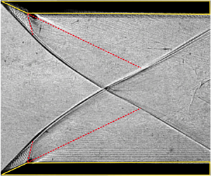
Figure 9(a–c) shows the comparison of shadowgraph images with the MoC results by superimposing both images. In figure 9(a), the shock curvature which is shown in red colour line is the MoC result and the black colour line indicates the shock captured by the shadowgraph method. The flow properties are  $M = 2.48$,
 $\theta _w = 22.69^{\circ }$ and
 $w/H = 0.30$. The pixel size in the shadowgraph image is calibrated with reference to a known dimension in the image. The distance between the tip of the top wedge and bottom wedge (refer to figure 8) is accurately measured using a Vernier gauge. In the shadowgraph image, this distance was identified and measured in terms of pixels. This procedure was done for three different shadowgraph images (refer to figure 9a–c), and one pixel is calibrated to be
 $0.56\pm 0.02\ {\rm mm}$. To find the
 $R/H$ value, the centre pixel at the reflection point in the image is identified and the horizontal distance from this point to the vertical line drawn through the tip of the wedges is taken in terms of pixels. This distance multiplied by the calibration factor
 $0.56\pm 0.02\ {\rm mm}$ will give the distance
 $R$, while the distance
 $H$ is already known. The same is done for all three images and the
 $R/H$ values are calculated and shown in table 2. Similarly, the approximate shock angle at the reflection point is found using the edge detection technique which uses the ‘difference of Gaussians’ algorithm and is particularly effective at detecting edges. The
 $R/H$ value and the local shock angle at the reflection point predicted by the MoC model and that obtained from the shadowgraph images for three different cases are shown in table 2. Table 3 shows a comparison of the
 $R/H$ values and the shock angle at the reflection point, predicted by three different models (the method of Bai (Reference Bai2023), MC method and MoC method). From table 3, it is evident that the reflection point and the shock angle at the reflection point vary for the three different models as the Mach number and the wedge angle increase.
Validation of analytical shock curvature with the experimental shadowgraph image for three short wedges.

Analytical (MoC) and experimental results for  $R/H$ and the local shock angle at reflection point.

 $R/H$ value and the local shock angle at the reflection point for three different models.

5. Results and discussion
The transition of the shock reflection in a short wedge depends on the extent of the interaction of the expansion fan with the incident shock wave. Due to the interaction of the expansion fan, the incident shock is weakened, resulting in a decrease in the shock angle at the reflection point compared with the case where there is no interaction. Therefore, the transition angle between RR and MR is modified. The value of the shock angle at the point of reflection depends on the degree of interaction of the expansion fan, or the  $w/H$ ratio, while
 $M$ and
 $\theta$ remain constant. As stated by Li & Ben-Dor (Reference Li and Ben-Dor1997), the transition angle is typically determined using the detachment criterion for
 ${\rm RR}\rightarrow {\rm MR}$ transition or the von Neumann criterion for
 ${\rm MR}\rightarrow {\rm RR}$ transition.
5.1. Transition lines – comparison with previous studies
Before discussing the results obtained using the present model, it would be appropriate to compare the results obtained with the previous models developed for the same flow phenomenon (Bai Reference Bai2023). It is important to know the deviation in obtaining the shock angle and the flow deflection angle at the reflection point using the model of Bai (Reference Bai2023). The model of Bai (Reference Bai2023) uses the parameter  $g$ to construct the transition lines. The analytical model developed by Bai (Reference Bai2023) only considers the interaction of C
 $-$ waves from the trailing edge and does not fully include the effect of reflected C+ waves from the incident shock wave. This approximation would create small errors in prediction of the shock angle at the reflection or triple point since the reflected C+ waves perturb the incoming adjacent C
 $-$ waves. When the C+ waves are also used to model the flow, as done in this work (MoC method), the slope of the incident shock in the vicinity of the reflection point will be higher when compared with the case where only the C
 $-$ waves are used (Bai Reference Bai2023). Therefore, when the flow is modelled using both the C+ and C
 $-$ waves, the shock angle at the reflection point will be higher when compared with that obtained using the model of Bai (Reference Bai2023) (refer to tables 4 and 5). Hence, this small error affects the prediction of the transition wedge angle at which the
 ${\rm RR}\leftrightarrow {\rm MR}$ transition takes place (i.e. for a given Mach number, the transition happens earlier for the MoC method compared with the model of Bai (Reference Bai2023). This error is evident near to the no-reflection line (red dashed line), as shown in figure 10. The black lines represent the
 $g$ lines constructed using the method suggested in the work of Bai (Reference Bai2023), whereas the blue lines are those constructed using the present MoC method. The maximum error is calculated by taking the wedge angle corresponding to the intersection point of the
 $g$ line (black colour) with the no-reflection boundary (red dashed line) and comparing it with that obtained using the MoC method, which is quantified and shown in tables 4 and 5. The point of intersection of the
 $g$ lines and the no-reflection line is different, as seen in figure 10.
Maximum error for  $g$ lines based on detachment criterion.

Maximum error for  $g$ lines based on von Neumann criterion.

Transition lines for different values of  $g$ based on (a) the detachment criterion and (b) von Neumann criterion.

Thus, it is evident that while the modelling approach developed by Bai (Reference Bai2023) matches the MoC method extremely well, there is a small but significant error near the no-reflection boundary. In the following sections, we will quantify the transition angles for the short wedges for various  $w/H$ ratios using the MoC method described in § 2 and validate these results with higher-order numerical simulations and shadowgraph images from experiments.
5.2. Transition lines – detachment criterion validation
The delay in the transition criterion, or the upwards shift in the detachment criterion line in figure 11(a) for the short wedge, can be attributed to the attenuation of the incident shockwave. The extent of the delay in this transition is determined by the  $w/H$ ratio. The determination of the detachment condition involves the solution of MoC for a specified Mach number
 $(M)$, wedge angle (
 $\theta$) and
 $w/H$. The detachment angle is generally shifted to higher angles for the shorter wedges and ends at the no-reflection domain. The no-reflection domain is the region above the red dashed line. Figure 11(a) shows the shift in the detachment criterion for a
 $w/H$ ratio of 0.5. The blue line represents the modified detachment criterion resulting from the interaction of the expansion fan with the incident shockwave, whereas the black solid line represents the detachment condition for long wedges in the absence of expansion fan interaction. Point S in figure 11(a) depicts the beginning of the interaction between the expansion fan and the incident shock wave for a given
 $w/H$ ratio. The deviation of the detachment condition occurs after this value, and for values below the interaction point (S), it remains the same as the long wedge. The point of shift (S) always depends on the extent of interaction and thus depends on the
 $w/H$ ratio. Interesting observations in the point of shift (S) for various
 $w/H$ ratios will be examined towards the end of this section. The transition line obtained from the MoC is validated with numerical simulations for
 $M = 3$ flow over a supersonic wedge; three cases are considered by keeping the Mach number constant and varying the wedge angle to comprehend the type of reflection obtained from the numerical simulations. The wedge angles are set to
 $\theta _w = 20^{\circ }, 25^{\circ }, 30^{\circ }$, respectively (points A, B and C in figure 11a), and
 $w/H$ is set to 0.5 (short wedge case) and 0.81 (long wedge case). Figure 11(b–e) depict the numerical Schlieren of the short wedge flow fields at points A, B and C, and the long wedge flow field simulation at point B. It can be seen from figure 11(b–e) that the shock reflections corresponding to points A and B are regular reflections, and C is the Mach reflection for the short wedge, while for point B, it is a Mach reflection for the long wedge. This confirms the shift of the transition line for a short wedge, making a regular reflection at point B, which was an erstwhile Mach reflection for the long wedge.
CFD results. (a) Transition line – Shift in detachment criterion for  $w/H = 0.5$. Flow configurations corresponding to points (b) A, (c) B, (d) C (all short wedges) and (e) case without interaction (long wedge), where
 $M =3$,
 $w/H = 0.5$ and
 $\theta = 20 ^{\circ }, 25 ^{\circ }, 30 ^{\circ }$, respectively, for short wedges, and
 $M=3$,
 $w/H = 0.81$ and
 $25^{\circ }$ for the long wedge.

The experimental validation of the shift in the transition line from the  $\theta _D$ curve is validated from the shadowgraph images from the experiments. Experiments were done for flow variables corresponding to P, Q and R as shown in figure 12(a), where the
 $w/H$ ratio is 0.30. At points P and Q, the flow variables are
 $M = 2.48$, and wedge angles are
 $\theta = 28.07 ^{\circ }$ and
 $22.69 ^{\circ }$, respectively. Point P is just above the blue colour transition line (
 $w/H =0.30$), as seen in figure 12(a), which results in an MR flow configuration as verified by the shadowgraph image in figure 12(b) from the experiment. Point Q is below the transition line, which results in an RR, as verified by the image in figure 12(c). At point R, the
 $w/H$ ratio is 0.617 (long wedge), where
 $M = 2.48$ and
 $\theta = 20.29 ^{\circ }$. This is above the
 $\theta _D$ curve (black colour), which should give an MR as validated by the image in figure 12(d). It is worth mentioning that the shock configuration is an MR for a long wedge (point R) and an RR for a short wedge (point Q). This confirms that the transition line has shifted to higher wedge angles when we use a short wedge. Thus, from the experiment results, it is clear that the transition line drawn for
 $w/H = 0.3$ predicts the
 ${\rm RR}\rightarrow {\rm MR}$ transition correctly. The slight asymmetry seen in the Mach stem in figure 12(b) is due to the small offset in the leading edge of the bottom wedge when compared with the top wedge (+0.3 mm), whereas that in figure 12(d) is due to a small error in the wedge angle (
 $\pm 0.2^{\circ }$).
Experimental results. (a) Transition line – Shift in detachment criteria for  $w/H = 0.30$. Flow configurations corresponding to points (b) P, (c) Q (both short wedges) and (d) R (long wedge); where
 $M =2.48$,
 $w/H = 0.30$ and
 $\theta = 28.07 ^{\circ }, 22.69 ^{\circ }$, respectively, for short wedges, and
 $M=2.48$,
 $w/H = 0.617$ and
 $20.29^{\circ }$ for the long wedge.

Similarly, experiments are done for Mach number 2.88 and  $w/H$ ratio 0.52, as shown in figure 13. At points S and T, the flow variables are
 $M = 2.88$, and wedge angles are
 $\theta = 28.07 ^{\circ }$ and
 $22.69 ^{\circ }$, respectively. Similar to the previous experiment, point S is just above the blue colour transition line (
 $w/H$ =0.52) and point T is below the transition line, as seen in figure 13(a). Point S corresponds to an MR flow configuration as verified by the shadowgraph image in figure 13(b) from the experiment. Point T is below the transition line, which results in an RR, as verified by the image in figure 13(c).
Experimental results. (a) Transition line – Shift in detachment criteria for  $w/H = 0.52$. Flow configurations corresponding to points (b) S and (c) T (both short wedges); where
 $M =2.88$,
 $w/H = 0.52$ and
 $\theta = 28.07 ^{\circ }, 22.69 ^{\circ }$, for points S and T, respectively.

Figure 14 demonstrates that for all  $w/H$ ratios, a combination of
 $M$–
 $\theta _w$ exists for which the interaction begins, and the transition line shifts from that point. Figure 14 shows that
 $w/H = 0.33$ begins to deviate from the detachment condition line at point S, where
 $M = 1.74$ and
 $\theta _w = 9.6^{\circ }$. The shift ends at the no-reflection condition at point E corresponding to
 $M = 3.38$ and
 $\theta _w = 36.3^{\circ }$. For
 $w/H = 0.33$, the region under the curve SEPD will be a combination of pure RR and dual solution domain, which eliminates pure MR flow configurations for any combination of Mach number and wedge angle in the region. If a
 $w/H$ ratio as small as 0.05 is used for the wedge, it can be seen from the figure 14 that we can even eliminate the pure Mach reflection completely and ensure that the entire
 $M$–
 $\theta _w$ plane will have regular reflection. Thus, the development of transition conditions for a shorter wedge has far-reaching implications that one can select a domain in which only a regular reflection occurs or control the size of the Mach reflection configuration by adjusting the
 $w/H$ ratio.
Transition line – Shift in detachment criterion for different  $w/H$ ratios.

From figure 14, it can be observed that for values of  $w/H$ ratio typically greater than 0.50, the point of shift (S) occurs at Mach numbers greater than 2, and for
 $w/H$ values less than 0.5, the point of shift (S) occurs at Mach numbers close to or less than 2. In fact, from the oblique shock relations, it is evident that for Mach numbers less than 2, the shock angle is comparatively more than that with Mach numbers greater than 2 for the same wedge angle. Thus, for Mach numbers less than 2, the point of intersection of the incident shock and the first expansion wave from the trailing edge (point B in figure 3), will occur only at very small wedge length
 $(w)$. Thus, in the case of bigger values of wedge length or larger
 $w/H$ ratios, and for flow Mach numbers say less than 2, the incident shock angle will meet the symmetry line before the first expansion wave intersects the incident shock. This flow characteristic is the same as that occurs in a long wedge. Thus, the transition line will remain the same as that for a long wedge unless the intersection occurs which leads to shock angle reduction due to interaction effects.
Figure 15 depicts the polar shock representation of a long and short wedge with a  $w/H$ ratio of 0.33. The incoming flow has a Mach number of 3 and a wedge angle of
 $30^{\circ }$. The post-shock Mach number at the reflection point for a long wedge is 1.41, while that for a short wedge is 2.04. The post-shock Mach number at the reflection point for a short wedge is higher due to the effective shock angle reduction at the reflection point due to the trailing edge expansion fan interaction. The shock polar also reveals that in the short wedge, due to the expansion fan interaction, there is a decrease in the required flow turn angle (
 $19.1^{\circ }$) at the reflection point, even though the wedge angle (
 $30^{\circ }$) remains unchanged. For a long wedge, the
 $\theta _{max}$ for the post-shock Mach number of 1.41 is
 $9.62^{\circ }$, whereas for the short wedge mentioned above, the post-shock Mach number is 2.04 and the
 $\theta _{max}$ is
 $23.65^{\circ }$.
Shock polar representation for  $w/H=0.33$.

Thus, at the reflection point, the required flow turn angle for a short wedge is  $19.1^{\circ }$, which is less than the
 $\theta _{max}$ value of
 $23.65^{\circ }$. This results in a regular reflection. The shock polar yields the MR solution corresponding to the long wedge and the RR solution corresponding to the short wedge.
5.3. Dual solution domain in short wedges
Another significant transition criterion in the wedge flows is the von Neumann criterion. Intuitively, it makes sense to assume that as the  $w/H$ ratio decreases, the von Neumann criterion line also shifts towards higher wedge angles, similar to the detachment condition. The dual solution domain, which is the region between the detachment criterion line and the von Neumann criterion line, also undergoes this shift. To comprehend the change in the dual solution domain, transition lines for the von Neumann criterion were also drawn for various
 $w/H$ ratios. The von Neumann criterion line for the short wedge is more complex than the detachment criterion, owing to the existence of the weak Mach reflection domain below Mach numbers 2.202 for air, which is marked as point B (bifurcation point) in figure 16(a). The shifts in the dual solution domain are divided into three categories as: Type I dual solution domain, in which the shift due to interaction occurs after the von Neumann point; Type II dual solution domain, where the detachment criterion line shift occurs before the von Neumann point; and Type III dual solution domain, where the von Neumann point itself has shifted due to high interaction and intersects the no-reflection line resulting in no dual solution domain. These peculiar flow phenomena are discussed in detail in the forthcoming sections below.
Dual solution domains for short wedges and long wedges (refer to the legend). (a)  $w/H=0.7$ shown in orange colour and long wedge shown in green colour; (b)
 $w/H=0.5025$ shown in blue colour and long wedge shown in green colour.

5.3.1. Type I dual solution domain
In the type I domain, the von Neumann point ‘B’ is identical to the long wedge flows, and the von Neumann criterion follows the long wedge path prior to expansion fan interaction and then shifts to higher wedge angles once the expansion fan interaction commences. The region above the red dashed line indicates a no-reflection domain where the shock waves are not attached to the wedge. To explain the shift in the dual solution domain, the whole dual solution region (region between the von Neumann criterion transition line and the detachment criterion transition line) is colour coded and shown in the legend of the figures for quick reference. For instance, in figure 16(a,b), the green colour region indicates the dual solution domain for long wedges (wedge with no expansion fan interaction with the incident shock). The dual solution domain region for  $w/H$ ratio 0.7 is shown as orange colour in figure 16(a). Note that this region overlaps the dual solution region for the long wedge (i.e. the orange colour overlaps the green colour). All these regions can be quickly identified from the legend of figure 16(a). Similarly, the dual solution region for
 $w/H$ ratio 0.5025 is shown as blue colour in figure 16(b) and the dual solution domain for long wedge is shown as green colour. The nature of the shift is explained as follows.
The von Neumann criterion ( $\theta _N$) line and detachment criterion (
 $\theta _D$) line for
 $w/H$ ratio 0.7 is shown in figure 16(a). The paths OBS
 $_D$D and OBS
 $_N$N represent the
 $\theta _D$ and
 $\theta _N$ lines for long wedges. Both the transition lines follow the same path as that for a long wedge, up to the points of shift (S
 $_D$ and S
 $_N$ for the detachment line and von Neumann line, respectively), then follow a different path as (S
 $_D$–D’ and S
 $_N$–N’) for a short wedge. The paths OBS
 $_D$D’ and OBS
 $_N$N’ represent the
 $\theta _D$ and
 $\theta _N$ line for a short wedge. The point of the shift of the
 $\theta _D$ line is at point S
 $_D$, where
 $M = 3.03$ and wedge angle
 $\theta _W =21.66^{\circ }$, whereas the point of the shift of the
 $\theta _N$ line is at point S
 $_N$, where
 $M = 3$ and wedge angle
 $\theta _W =$19.66
 $^{\circ }$. As the
 $w/H$ value decreases from 0.7, the point of shifts S
 $_D$ and S
 $_N$ moves to the direction of the von Neumann point B, and merges with the point B, where
 $M = 2.202$,
 $\theta _W=$15.15
 $^{\circ }$ and the
 $w/H$ ratio is 0.5025, as shown in figure 16(b). Thus, short wedges with
 $w/H$ ratios greater than 0.5025 will give a Type I dual solution domain. The characteristic of this type is that the weak Mach reflection or von Neumann point B remains the same for all
 $w/H$ ratios greater than 0.5025 since both the points of shift from the detachment line and von Neumann line S
 $_D$ and S
 $_N$ occur after point B.
5.3.2. Type II dual solution domain
As illustrated in figure 17, the type II dual solution domain occurs when the detachment condition occurs prior to the von Neumann point B for  $w/H$ ratios less than 0.5025. Consequently, the type II domain begins at
 $w/H$ = 0.5025 and ends at
 $w/H$ = 0.21, where the von Neumann point (B) reaches the no-reflection line (point B”’ in figure 17). The dual solution domains for
 $w/H$ ratios 0.25, 0.33, 0.5025, and long wedge are shown in figure 17. In the figure, for the long wedges, paths OBD and OBN represent the
 $\theta _D$ and
 $\theta _N$ lines, respectively. The dual solution region for the long wedge is colour coded as green. Path OBD’
 $_{(0.5)}$, OBN’
 $_{(0.5)}$, represents the same for short wedge of
 $w/H$ ratio 0.5025. The dual solution region for the short wedge with a
 $w/H$ ratio of 0.5025 is colour coded as blue. This ratio corresponds to the start of the Type II dual solution domain. The dual solution regions for different
 $w/H$ ratios can be easily identified by referring to the legend in figure 17.
Dual solution domains for long and short wedges.

For short wedge with  $w/H$ ratio 0.33, the
 $\theta _D$ line and
 $\theta _N$ line follow the path OB'D’
 $_{(0.33)}$ and OB'N’
 $_{(0.33)}$, respectively, as shown in figure 17. The dual solution region for this short wedge with
 $w/H$ ratio of 0.33 is colour coded as red. The dual solution region for this case is quite interesting. The detachment criterion line intersects the no-reflection line at point 3 and then follows the no-reflection line boundary (red dashed line) and ends at D’
 $_{(0.33)}$. A major part of the dual solution domain is between the no reflection line boundary and the
 $\theta _{N'0.33}$ line. Thus, in this case where the
 $w/H$ ratio is 0.33, the pure Mach reflection is confined to a very small region in the
 $M$–
 $\theta _w$ plane, which is in between the no-reflection line (red dashed line) and the curve O-S
 $_{D(0.33)}$-3. In § 5.2 (refer figure 14), it has been seen that pure Mach reflections can be completely turned into regular reflections for very small
 $w/H$ ratios. In the following discussion, we will find out a
 $w/H$ ratio to completely avoid the dual solution domains.
The  $\theta _D$ line and
 $\theta _N$ line for
 $w/H$ ratio 0.25 are shown as path OB”1 and OB”2, respectively. The dual solution domain for
 $w/H=0.25$ is extremely small, as seen in the zoomed-in picture in figure 17. The dual solution domain is hardly visible for wedges with
 $w/H$ ratios less than 0.25. Thus, for short wedges with
 $w/H$ ratios less than 0.5025, the von Neumann point B shifts in the direction of the no-reflection domain and eventually meets the no-reflection line at point B”’, where the
 $\theta _D$ line of
 $w/H$ ratio 0.21 intersects with the no-reflection line. Moreover, the characteristic nature of Type II dual solution domains is that, as the
 $w/H$ value is reduced from 0.5025 to 0.21, the dual solution domain diminishes and shifts towards the no-reflection domain.
5.3.3. Type III dual solution domain
The von Neumann solution does not exist for long wedges for Mach numbers less than 2.202, where the wedge angle  $\theta _w=$15.15
 $^{\circ }$. However, in short wedges, as the
 $w/H$ ratio decreases, the wedge angle corresponding to the von Neumann point moves to higher wedge angles. The limiting case of this shift in wedge angle is when the von Neumann point intercepts the no-reflection line shown as point B”’ in figure 17. The value of the
 $w/H$ ratio whose
 $\theta _D$ line passes exactly through this point B”’ will give the limiting point of von Neumann solutions in short wedges. The value calculated is very close to 0.21, neglecting the numerical errors. The
 $\theta _D$ line for
 $w/H$ ratio 0.21 is shown in figure 17 as path OB”’, in which point S
 $_{D(0.21)}$ is the point of the shift from the
 $\theta _D$ line, where
 $M=1.44$ and
 $\theta =5.3^{\circ }$. The von Neumann point is at point B”’, where
 $M=2.202$ and wedge angle
 $\theta =25.93^{\circ }$. Thus, the
 $M$–
 $\theta _w$ parameter space where the value of
 $w/H$ is less than 0.21 characterises the type III domain. Type III domain differentiates itself from the other two domains as no dual solution domain exists in this type, and only pure MR and pure RR exist. However, the region for pure MR is confined to a very small space in the
 $M$–
 $\theta _w$ plane.
5.3.4. Locus of the von Neumann points
Shifting the von Neumann point is one of the defining characteristics of the short wedge flows. It is evident from the preceding discussion that for  $w/H$ ratios less than 0.5025, the von Neumann point moves, and figure 18 illustrates the locus of shift of the von Neumann points in the red dashed line (the line connecting points
 $S_{D(0.5025)}$ and
 $B_{0.21}$ in figure 18) for various
 $w/H$ ratios. This demarcation line divides the
 $M$–
 $\theta _w$ space into two distinct areas. Dual-domain solutions do not exist on the left-hand side of the line, but exist on the right. The shift in von Neumann points in the
 $M$–
 $\theta _w$ parameter space follows a straight line passing through the
 $x$-intercept where
 $M=2.202$. Although the dual solution domain exists on the right-hand side of the above-mentioned straight line, the domain close to this line is hardly visible due to the interaction effects, as shown in the enlarged views of regions B1 and B2 in figure 18. To confirm the shift in von Neumann point B, shock polars of short wedges with actual wedge angle and effective wedge angle (turn angle at reflection point) are drawn. Figure 19 shows the shock polar for
 $w/H$ ratio 0.33 at the von Neumann point B
 $_{0.33}$ (refer to region B2 in figure 18). The solid blue line indicates r-polar for the actual wedge angle used, and the dashed blue line shows the same for the effective wedge angle
 $\theta _{eff}$ at the reflection point R (refer to figure 3). At point B
 $_{0.33}$, the wedge angle is 20.18
 $^{\circ }$ and due to interaction, this is reduced to 15.15
 $^{\circ }$. Thus, the von Neumann shift in short wedge flows is validated with the shock polar. Further investigations are required to comprehend the shock reflection configurations and the flow behaviour in Type I, Type II and Type III interactions in the flow over short wedges.
Locus of bifurcation points for various  $w/H$ ratios.

Shock polar for  $M=2.202$,
 $w/H$ ratio 0.33.

6. Conclusion
The shock reflection phenomena on short wedges have been investigated using analytical, computational and experimental methods. The interaction of the expansion fan emanating from the trailing edge of the short wedge with the incident shock wave is found to curve the incident shock. The curving of the incident shock wave leads to the change of shock angle at the reflection/triple point, consequently leading to a shift in the transition line. The transition lines plotted for different  $w/H$ ratios from 0.05 to 0.8 show that the shift in transition lines depends on the extent of interaction. The plot is useful in finding the detachment/von Neumann criterion for any Mach number between 1 and 5 for a particular
 $w/H$ ratio. Moreover, we can control the appearance of MR or its configuration for a particular Mach number by selecting the suitable (
 $w/H$) ratio from the transition lines generated. As the extent of expansion fan interaction with the incident shock increases, the dual domain shifts its location. Based on the pattern of shift the dual solution regimes are classified into Type I, Type II and Type III domains. The dual solution domain eventually diminishes as a function of
 $w/H$ ratio, facilitating the control of the
 ${\rm MR}\leftrightarrow {\rm RR}$ hysteresis process.
Declaration of interests
The authors report no conflict of interest.
Appendix A. Analytical modelling
This section explains in detail the algorithm developed and governing equations used to find the curvature of the incident shock due to the interaction of the trailing edge expansion waves of the same family. The reference book for developing the algorithm is Zucrow & Hoffmann (Reference Zucrow and Hoffmann1977).
The present study assumes steady, two-dimensional planar flow of a perfect gas which is rotational in nature. Two algorithms are developed, one to find the interior points in the flow field and the other to find the discrete points on the shock. The incoming flow is assumed to be horizontal. After the initial deflection of the flow at leading edge of the wedge, the flow near the trailing edge turns back to horizontal direction due to the expansion fans from the trailing edge. To achieve this, the shoulder of the wedge is made parallel to the line of symmetry. The coordinate system used in the solving algorithm and the framework of number system to denote the position in the flow field is as shown in figure 20.
Framework for solution algorithm in MoC.

The input to the code is Mach number ( $M_0$), wedge angle (
 $\theta _w$) and
 $w/H$ ratio. The stagnation pressure (P
 $_0$) and temperature (T
 $_0$) are assumed to find the flow property values. With this input, the
 $x$,
 $y$ coordinates of the trailing edge, point D
 $(1,1)$, as shown in figure 20, are calculated. The first expansion line is drawn from point D after finding the Mach angle as
 $\mu = {\rm arcsin}(1/M_1)$, where
 $M_1$ is the Mach number post shock. This will intersect the incident shock at B
 $(1,2)$ as shown in figure 20. The flow property values of pressure (
 $p$), density (
 $\rho$), velocity (
 $V$), flow turn angle (
 $\theta$) are calculated at point B using the oblique shock relations.
To begin the algorithm, a small turn angle  ${\rm d}\theta$ is assumed to happen at the trailing edge (point D). For this flow turn angle, the flow property values are calculated at point D
 $(2,1)$ from the Prandtl–Meyer relations and isentropic relations shown in (A1)–(A2). Note that at point D, although the
 $(x,y)$ location remains the same, the flow property value changes depending on the turn angle in each step. Now the initial data points are D
 $(2,1)$ and B
 $(1,2)$. With these points, the next interior point B
 $_1$
 $(2,2)$ is calculated as follows:
 $$\begin{gather} \nu_{i} = \sqrt{\frac{\gamma+1}{\gamma-1}}\tan^{-1}{\sqrt{\frac{\gamma-1}{\gamma+1}(M^2_i-1)}} - \tan^{-1}{\sqrt{M^2_i-1}}, \end{gather}$$
 $$\begin{gather}\dfrac{p_i}{p_{01}} ={\left(1 + \frac{\gamma-1}{2}M^2_i\right)^{({\gamma-1})/{\gamma}}}, \end{gather}$$
where
 \begin{equation} i=1,2,3,\ldots\quad \text{at point}\ D. \end{equation}
From the characteristic equations given in table 1, the following four ((A4)–(A7)) are written in the finite difference form. These equations are simultaneously solved for obtaining values x $_S$, y
 $_S$, x
 $_{B1}$ and y
 $_{B1}$. The properties such as
 $V,\theta,p$ and
 $\rho$ at point S are obtained by linear interpolation (line DB). Note that as shown in (A11) and (A12), the value of
 $\theta _S$ is computed by the iterative method. For each iteration, the value of
 $\theta _S$ is linearly interpolated and substituted in (A4), and the value of x
 $_S$ is computed till the difference from this value and the previous value is minuscule.
 $$\begin{gather} \dfrac{(y_S - x_S)}{(y_{B1} - x_{B1})} = \lambda_0 , \end{gather}$$
 $$\begin{gather}\dfrac{(y_{B1} - x_{B1})}{(y_D - x_D)} = \lambda_+ , \end{gather}$$
 $$\begin{gather}\dfrac{((y_{B1} - x_{B1})}{(y_B - x_B)} = \lambda_- , \end{gather}$$
 $$\begin{gather}\dfrac{(y_S - x_S)}{(y_B - x_B)} = \lambda_{DB}\quad (\text{slope of line DB}), \end{gather}$$
where
 $$\begin{gather} \lambda_+= \tan(\theta+\mu), \end{gather}$$
 $$\begin{gather}\lambda_-= \tan(\theta-\mu), \end{gather}$$
 $$\begin{gather}\lambda_0 = \tan(\theta_S) , \end{gather}$$
 $$\begin{gather}{\rm where}\quad \theta_S = \dfrac{(\theta_D + \theta_B)}{2} \quad(\text{first guess}), \end{gather}$$
 $$\begin{gather}{\rm and}\quad \theta_S = \dfrac{(\theta_S + \theta_{B1})}{2} \quad (\text{next iteration}). \end{gather}$$
The compatibility equations along the C $-$ and C+ lines can be written in the finite difference form as
 $$\begin{gather} Q_+(\,p_{B1}-p_B) + (\theta_{B1}-\theta_B) = 0, \end{gather}$$
 $$\begin{gather}Q_-(\,p_{B1}-p_D) - (\theta_{B1}-\theta_D) = 0, \end{gather}$$
where
 \begin{equation} Q_+= \dfrac{\sqrt{M^2_B-1}}{\rho_B V^2_B} \quad {\rm and}\quad Q_-= \dfrac{\sqrt{M^2_D-1}}{\rho_D V^2_D}. \end{equation}
The compatibility equations along the stream line C $_0$ can be written in the finite difference form as
 $$\begin{gather} R_0(V_{B1}-V_S) + (\,p_{B1}-p_S) =0, \end{gather}$$
 $$\begin{gather}(\,p_{B1}-p_S) - A_0(\rho_{B1}-\rho_S) =0, \end{gather}$$
where
 \begin{equation} R_0 = \rho_S V_S \quad {\rm and}\quad A_0 = a^2 = \dfrac{\gamma p_S}{\rho_S}. \end{equation}
Equations (A13)–(A17) can be solved to get values  $p,\theta, \rho$ and V, at point B
 $_1$. The values found till now, including the location of B
 $_1$
 $(2,2)$ and the flow property values
 $V, \theta, p$ and
 $\rho$ at that location, form the predictor values of an Euler predictor algorithm. Improved values (corrector) for the location B
 $_1$
 $(2,2)$ and the corresponding flow property values
 $V, \theta, p$ and
 $\rho$ at that location may be obtained by repeating the steps discussed above for the Euler predictor algorithm by using average values of
 $V, \theta, p$ and
 $\rho$ along each characteristic line. For instance, for C+ characteristic line, the values may be recalculated by taking the average as
 \begin{equation} \lambda_+= \tan(\theta_{+} +\mu_+), \end{equation}
where
 \begin{align} p_+= \dfrac{(\,p_B+p_{B1})}{2},\quad \theta_+= \dfrac{(\theta_B+\theta_{B1})}{2},\quad V_+= \dfrac{(V_B+V_{B1})}{2},\quad \rho_+= \dfrac{(\rho_B+\rho_{B1})}{2}. \end{align}
Additionally, sound velocity, Mach number and Mach angle can be averaged as
 \begin{equation} a_+=\sqrt{ \dfrac{\gamma p_+}{\rho_+}} ,\quad M_+= \dfrac{V_+}{a_+} ,\quad \mu_+= a\sin\dfrac{1}{M_+}. \end{equation}
Thus, the modified Q $_+$ can be calculated as
 \begin{equation} Q_+= \dfrac{\sqrt{M^2_{+}-1}}{\rho_+ V^2_+}. \end{equation}
The coefficients  $\lambda _-, \lambda _0, Q_-,R_0$ and
 $A_0$ are determined in a similar manner. The corrector can be iterated to achieve the required accuracy level. The above steps are repeated till the required convergence is met. This completes the interior point calculation algorithm.
The next point in the framework is C  $(2,3)$, which is a point on the curved shock. Since the MoC equations are not valid across the shock, oblique shock relations are used across the shock, and the characteristic and compatibility equations are used post shock to solve this point. At this point C
 $(2,3)$, the shock angle has reduced from
 $\phi _1$ to
 $\phi _2$ due to the expansion wave interaction as shown in figure 20. The subsequent part of this algorithm is developed to find out the modified shock angle and the flow properties post shock at point C. This is obtained by an iterative method which is explained as follows.
First, a pressure ratio across the shock at that vicinity is assumed. The best guess is the pressure at point B  $(1,2)$. In fact, in the MC approach, this pressure is taken as the post-shock pressure and the shock angle is calculated accordingly. Here, we use the pressure at B
 $(1,2)$ to find the pressure ratio across the shock as (
 $p_B/p_\infty$) and use that value as the first guess. With the incoming Mach number (
 $M_\infty$) and assumed pressure ratio (
 $p_B/p_\infty$), the shock angle (
 $\phi _2$) and the flow turn angle
 $\theta _C$ at point C
 $(2,3)$ is calculated. For the C
 $-$ characteristic line from B
 $_1$
 $(2,2)$ to C
 $(2,3)$, the compatibility equation given in table 1 is written in the finite difference form as
 \begin{equation} Q_-(\,p_{B1}-p_C) - (\theta_{B1}-\theta_C) = 0, \end{equation}
where
 \begin{equation} Q_-= \dfrac{\sqrt{M^2_{B1}-1}}{\rho_{B1} V^2_{B1}}. \end{equation}
The  $\theta _C$ value calculated at point C from the first guess is then incorporated into (A23) and the pressure (
 $p_C)$ at C is calculated. This pressure should match with the post-shock pressure calculated from the guess. The procedure is repeated till the required convergence is met. Its worth mentioning that the C
 $-$ characteristic line starting from point D, which ends at the curved shock, is slightly modified by the C+ lines which are generated from the incident curved shock. To find the next local shock angle
 $\phi _3$, the next characteristic line is generated for the next increment in flow turn angle (
 ${\rm d}\theta$) at the point indicated as D
 $(3,1)$ as shown in figure 20. The flow property values
 $V, \theta, p$,
 $M$ and
 $\rho$ at locations
 $(3,1)$,
 $(3,2)$,
 $(3,3)$ and
 $(3,4)$ are calculated and the local shock angle (
 $\phi _3$) at location
 $(3,4)$ is obtained using the algorithm mentioned above. To construct the curvature of the shock, the adjacent shock angles are averaged. The algorithm is executed till the flow at point D has become horizontal, or the curved shock hits the line of symmetry. The exact point of intersection of the curved shock with the line of symmetry, (x
 $_{int}$,y
 $_{int}$) as shown in figure 20, is obtained by a linear interpolation between the points
 $(3,4)$ and
 $(4,5)$. The shock angle (
 $\phi _R$), flow turn angle (
 $\theta _{eff}$) and all the flow properties at this intersection point are obtained by linear interpolation.
The minimum step size ( ${\rm d}\theta$ in degrees) required for the accurate prediction of the curvature of the incident shock is found out by reducing the value of (
 ${\rm d}\theta$) from 0.1
 $^{\circ }$ to 0.005
 $^{\circ }$ and computing the corresponding
 $R/H$ values and shock angle
 $\phi _R$ at the reflection point for each case. The results for two cases are shown in table 6 and the optimum step size (
 ${\rm d}\theta$) for executing the algorithm is taken as 0.03
 $^\circ$.
MoC results to find the convergence in step size ( ${\rm d}\theta$).


 Open access

