I. INTRODUCTION
Nanotechnology has played a significant role in the development of useful engineering devices and in the synthesis of new classes of materials. For the reliable design of miniaturized devices and for the structural applications of nano- or microsized materials, nanotechnology has always called for an understanding of the mechanical properties of materials at small length scales.Reference Nix, Greer, Feng and Lilleodden1 Recently, micropillars, which are commonly fabricated by focused-ion-beam (FIB) milling, have been used extensively to study size effects on the mechanical properties of materials without significant strain gradients.Reference Uchic, Dimiduk, Florando and Nix2–Reference Volkert and Lilleodden4 However, FIB irradiation generates various defects, such as dislocation loops, precipitates, Ga+ ion implantation, and amorphous layers near the free surfaces, which might be expected to alter the mechanical properties.Reference Kiener, Motz, Rester, Jenko and Dehm5 When the sample dimensions are reduced to the submicrometer scale, the FIB-damage effects might be particularly significant because of the high volume fraction of the damaged material. For these reasons, specimen preparation techniques that do not involve FIB irradiation are desired, not only to avoid the effects of FIB damage on the mechanical properties being studied but also to provide a non-FIBed reference that can be used to study the effects of FIB irradiation systematically.
Several synthesis techniques, which do not use FIB irradiation, have been developed for producing high-quality mechanical test samples; these include the directional solidification/matrix etching technique,Reference Bei, Shim, George, Miller, Herbert and Pharr6 the molecular-beam epitaxy method,Reference Richter, Hillerich, Gianola, Mönig, Kraft and Volkert7 the electroplating method,Reference Jennings, Burek and Greer8 and the liquid-Reference Sadan and Kaplan9 or solid-dewettingReference Mordehai, Kazakevich, Srolovitz and Rabkin10 techniques. BCC Mo-alloy pillars produced by chemical etching of the matrix from directionally solidified NiAl–Mo eutectic composites have been especially informative because the pillars are dislocation-free in the as-solidified state and the dislocation density can be altered by prestraining the compositeReference Bei, Shim, Pharr and George11 before the pillars are made. Pristine Mo-alloy pillars show size-independent yield strengths over a wide range of pillar sizes. Their yield strengths are very close to the ideal, theoretical strength, unlike FIB-milled Mo pillarsReference Bei, Shim, George, Miller, Herbert and Pharr6 which are much weaker and also exhibit size-dependent strengths. Prestrained Mo-alloy pillars show a dramatic decrease in yield strength. Heavily prestrained (11% strain) pillars show bulk-like behavior with smooth stress–strain curves and conventional strain hardening.Reference Bei, Shim, Pharr and George11 Furthermore, FIB milling reduces the strength of Mo-alloy pillars down to that of 11% prestrained pillars.Reference Shim, Bei, Miller, Pharr and George12 In sum, this set of experiments on BCC Mo-alloy pillars was especially important and influential because it allowed for the systematic study of the effects of FIB irradiation and prestraining on the mechanical properties of these pillars. Here, we describe a similar study of the mechanical properties of a pure, FCC metal crystal, gold, and the effects of FIB irradiation and prestraining on those properties.
Recently, we have successfully produced FCC single-crystalline pure Au microparticles on a sapphire substrate by the solid-state diffusion dewetting technique.Reference Mordehai, Kazakevich, Srolovitz and Rabkin10 The size of these microparticles is in the range from 200 nm to 1 μm (top diameter), and each microparticle has a flat top surface with a <111> orientation. In our previous research,Reference Mordehai, Lee, Eckert, Srolovitz, Nix and Rabkin13 we were able to study the apparent size effects of pristine microparticles using microcompression tests. In the present article, we study the effects of three different types of postgrowth treatments. These include the effects of prestraining, FIB irradiation, and FIB irradiation after prestraining. The stress–strain behaviors for these three different conditions are used to examine the effects of initial defect structures and FIB damage on the mechanical properties of Au microparticles with/without mobile dislocations.
II. EXPERIMENTAL
A. Sample preparation and mechanical tests
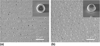
Polycrystalline Au thin films, 10 nm thick, were deposited using magnetron sputtering on a <0001> sapphire substrate. Then, the films were annealed at 900 °C (T m,Au = 1064 °C) for 10 h in air. At this high temperature, Au atoms agglomerate to form microparticles via solid-state diffusion. Figure 1 shows the distribution of Au microparticles on a sapphires substrate. There is a large spectrum in shape and size. All microparticles have a flat top surface with a <111> normal, which has the threefold rotational crystallographic symmetry. However, some microparticles do not retain a symmetric shape but are elongated. Thus, the microparticles, which are symmetric in shape and also relatively tall, were selected for mechanical testing, as seen in the insets of Fig. 1. A more detailed description of the microparticle formation was provided in Ref. Reference Mordehai, Kazakevich, Srolovitz and Rabkin10. All secondary electron microscope (SEM) images in this article were obtained with the operating voltage of 5 kV.
Secondary electron microscope (SEM) images of Au microparticles synthesized by a solid-state-diffusion dewetting technique; (a) top view and (b) 52° tilted view. The insets show the individual Au microparticle with the ∼600 nm top diameter. The small triangle in the inset of (a) indicates the threefold rotational symmetry of <111> axis.

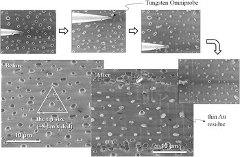
The white triangle in Fig. 2 indicates the size of the flat-punch tip of our nanoindenter. The tip size is much larger than the average distance between microparticles. To avoid compressing multiple microparticles during the mechanical tests, selected Au microparticles were isolated mechanically using the tungsten Omniprobe micromanipulator of the FEI Strata 235DB dual-beam FIB machine (FEI). To minimize the effects of geometrical difference on the data, we tried to find Au microparticles with the self-similar shape. Figure 2 shows the mechanical isolation process. Because the adhesion between the microparticles and the sapphire substrate is relatively strong, Au residues remained on the substrate after mechanical isolation.
Mechanical isolation process using a tungsten Omniprobe micromanipulator. The white triangle indicates the size of the flat-punch tip used in this study.

The compression tests were performed using an Agilent Technologies nanoindenter XP with a flat-punch tip with a projected area of an equilateral triangle, 8 μm on a side. All tests were performed under a constant nominal displacement rate of 2 nm/s. Load–displacement data were measured after a thermal drift became less than 0.05 nm/s. Because of the complex geometry of the microparticle, the stress distribution is not homogeneous. Yielding is expected to occur at the top surface with the smallest cross section. Thus, the stress was calculated by dividing the applied load by the initial top area. This nominal stress at the top surface does not represent a nonuniform stress field in the Au microparticles, but this simple calculation could provide some insight to study size effects on the strength of Au microparticles. In our previous study, we showed that size effects for pristine microparticles, which were evaluated by this simple calculation, can be explained in terms of the size dependence of the critical stress for dislocation nucleation in the presence of strain gradients.Reference Mordehai, Lee, Eckert, Srolovitz, Nix and Rabkin13 The constraining effects caused by the friction at the top surface and the adhesion at the bottom surface are ignored in this stress calculation. The finite element analysis revealed that the constraining effects at the top and bottom of Au microparticles do not affect the stress fields near the top surface significantly.Reference Mordehai, Lee, Eckert, Srolovitz, Nix and Rabkin13 The elastic modulus of the <0001> sapphire substrate (435 GPa) is much greater than that of the <111> Au microparticle (116 GPa). As a consequence, the elastic displacement of the sapphire substrate, which is calculated by the Sneddon punch equation, is negligible compared to the total displacement. Thus, we used the nominal axial strain, which was calculated simply by dividing the total displacement by the initial height.
B. FIB irradiation and prestraining
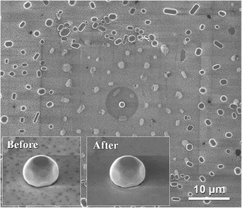
To study the effects of FIB irradiation on the yield strength, the FEI Strata 235DB dual-beam FIB machine was used with an operating voltage of 30 kV. The Au microparticles with the top diameter from 200 nm to 1 μm were exposed to the Ga+ ion beam. First, the Au microparticle was scanned at 12,000 times magnification in the ion-beam mode to find the exact position of the target microparticle. Then, to avoid the heavy dose of Ga+ ions, which may cause the significant change in shape, a 10 pA beam was applied through the 5-μm diameter circular pattern for 7 s. The pattern size is much larger than the microparticle sizes to reduce the current density of the ion beam. Figure 3 shows a dark circular area around the target microparticle which was FIB-irradiated. The insets show no significant difference in shape before and after the FIB irradiation at our SEM resolution.
SEM images of the Au microparticle exposed to the Ga+ ion beam through the 5-μm diameter circular pattern. The insets show the Au microparticle before and after the ion-beam exposure, and there is no significant change in shape.

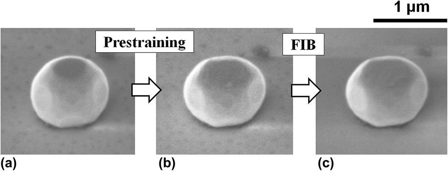
Just after yielding, pristine Au microparticles always collapse rapidly, resulting in a huge dislocation avalanche. Thus, it is necessary to take special precautions in prestraining to prevent the huge strain bursts from occurring. We developed a nanohammering technique to accomplish this. We used the continuous stiffness mode of the nanoindenter with a large amplitude (8 nm) and a high frequency (140 Hz). If the sample height is h and the stiffness and irregular shape of Au microparticles are ignored, the effective engineering strain rate can be approximated as (8 × 140 s−1 × 2)/h = 2240/h s−1. The number 2 considers the up and down motion of the indenter tip. However, it is difficult to obtain the true strain rate because the true strain rate is spatially and temporally heterogeneous due to the stochastic propagation of highly localized strain bursts and the irregular shape of microparticles. This hammering method allows the indenter tip not only to lose contact with the microcrystal after yielding but also to transfer a high impact to the microcrystal during a short time period. Thus, we were able to introduce a certain amount of plastic strain without the huge strain burst. Au microparticles with a top diameter of ∼400 nm were prestrained. Figures 4(a) and 4(b) show the particle shape before and after prestraining; the lateral dimension naturally increased with plastic deformation. The amount of prestrain was rather variable since we could not precisely control the strain bursts. So, we studied a range of prestrains from 10 to 40%.
(a) The pristine, (b) prestrained, and (c) prestrained/FIB-irradiated Au microparticle. The Au microparticle in these SEM images is the identical one.
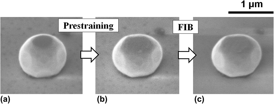
It is of interest to study the effects of FIB damage layers on prestrained microparticles. It is an open question whether the defects in the FIB damage layers would weaken or harden the prestrained Au microparticles. Thus, we first prestrained Au microparticles with a top diameter of 400 nm to introduce mobile dislocations and then exposed them to the Ga+ ion beam at the same condition described above. The experimental procedure is illustrated in Fig. 4.
III. RESULTS
A. Effects of FIB irradiation and prestraining
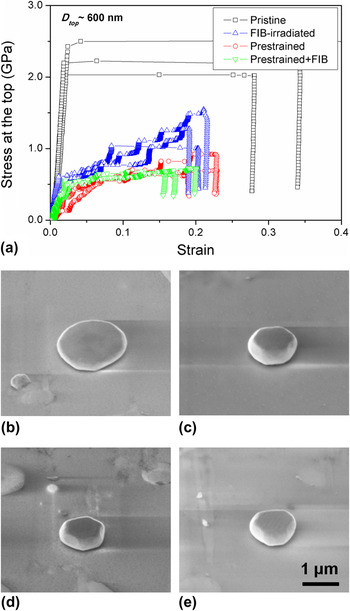
Figure 5 shows the stress–strain curves for the pristine, FIB-irradiated, prestrained, and prestrained/FIB-irradiated Au microparticles with a top diameter of ∼600 nm. Pristine Au microparticles exhibit elastic loading followed by a huge initial strain burst, and Fig. 5(b) shows a pancake shape after the mechanical test. The yield strengths of pristine Au microparticles are much higher than the yield strengths of the other three cases. The stress–strain curves for pristine Au microparticles with various sizes were provided in Ref. Reference Mordehai, Lee, Eckert, Srolovitz, Nix and Rabkin13
(a) Stress–strain curves of the pristine, FIB-irradiated, prestrained, and prestrained/FIB-irradiated Au microparticles. The SEM images show the deformed shapes of microparticles for the four cases in the stress–strain curves; (b) pristine, (c) FIB-irradiated, (d) prestrained, and (e) prestrained/FIB-irradiated Au microparticles after the mechanical tests.

Both FIB irradiation and prestraining reduce the yield strength of the Au microparticles significantly. Furthermore, the stress–strain curves become jerky and similar to the behavior seen for FIB-milled micropillars.Reference Lee, Han and Nix14 These results are also similar to those for FIB-milled or prestrained Mo-alloy pillars.Reference Bei, Shim, Pharr and George11, Reference Shim, Bei, Miller, Pharr and George12Figures 5(c) and 5(d) show the deformed Au microparticles for FIB irradiation and prestraining, respectively. Because the strain bursts are relatively small, the microparticles could be deformed in a relatively stable manner and pancaking was avoided.
The stress–strain curves of prestrained microparticles are similar with those of prestrained/FIB-irradiated ones. The existence of surface damage evidently does not alter the stress–strain behavior of Au microparticles with preexisting mobile dislocations. Therefore, while FIB irradiation affects the yield strength and the stress–strain behavior of pristine microparticles significantly, it does not affect the properties of prestrained microparticles.
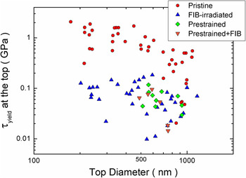
Figure 6 shows the shear yield strength of these microparticles as a function of the top diameter of the crystal. The shear yield strength was obtained by multiplying the yield strength by the Schmid factor for the <111> loading axis, assuming uniaxial loading. In our experiment, it is easy to detect the point of yielding from the stress–strain curve because most stress–strain curves clearly show distinct transitions between elastic and plastic deformation at the first strain burst. Thus, we used the yield strength rather than the flow stress, which is commonly used in most micropillar studies. The pristine microparticles show an apparent size dependence of the yield strength. However, the existence of size effects for the prestrained and the FIB-irradiated microparticles could not be determined due to the wide scatter in the data. However, the reduction of yield strengths by prestraining and FIB irradiation is clearly observed.
The shear yield strength as the function of sample top diameter for the pristine, FIB-irradiated, prestrained, and prestrained/FIB-irradiated Au microparticles.

B. Some concerns in the data analysis
The stress levels in the stress–strain curves of prestrained Au microparticles are overestimated due to a shape effect. Pristine or FIB-irradiated microparticles are nearly devoid of mobile dislocations. Thus, yielding would occur by the heterogeneous nucleation of dislocations at the edges of the top surface where the cross section is smallest. In this case the use of the stress at the top surface of the microcrystal would be appropriate. However, in the case of prestrained and prestrained/FIB-irradiated microparticles, mobile dislocations would exist over the entire sample volume, with the consequence that a dislocation source might operate near the center of the microparticle where the stress is lower than that reported in Fig. 5.
FIB irradiation produced a decrease in yield strength similar to that for prestraining. The decrease is expected to depend on the dose of the Ga+ ion beam. In this article, we studied only one dose condition, as described in Section II.B. Thus, the similarity of stress–strain curves between prestrained and FIB-irradiated microparticles might be fortuitous.
IV. DISCUSSION
A. The effects of FIB irradiation
FIB irradiation is known to produce various kinds of defects near the free surface. Precipitates or amorphous layers could cause hardening since they could prevent the motion of mobile dislocations.Reference Kiener, Motz, Rester, Jenko and Dehm5 However, if a specimen does not have mobile dislocations, the plasticity would initiate at the free surface by dislocation nucleation. The surface damage caused by FIB irradiation, such as surface roughness or injected dislocation loops, would be expected to reduce the yield strength of a defect-free crystal. In the present study, FIB irradiation reduced the yield strength of pristine microparticles very significantly. Therefore, the FIB damage appears to facilitate dislocation nucleation at the free surface, as expected. However, the origin of the jerky stress–strain behaviors of FIB-irradiated microparticles is uncertain. Even though the specimen does not contain a bulk source, the intermittent nucleation of dislocations at the damage layer can produce the jerky stress–strain behavior.Reference Greer and Nix15 Also, bulk sources (single-pinned or double-pinned source) can also produce jerky stress–strain curves as typically seen for large micropillars. Brinckmann et al. showed remarkably similar size distributions of displacement bursts between dislocation-starved Au nanopillars and dislocation-containing Ni micropillars, both of which were FIB-milled.Reference Brinckmann, Kim and Greer16 Thus, it is not easy to identify the origin of jerky stress–strain behavior only from the stress–strain curves. According to our prestraining experiments, some amount of plastic deformation would introduce mobile dislocations into the microparticles. Because of the low aspect ratio of microparticles, compared to micropillars, dislocations could then be piled-up and multiplied as seen in the low aspect ratio Au micropillars.Reference Lee, Han and Nix14 Even though dislocation pile-up does not occur, however, some mobile dislocations could interact with each other and produce a bulk source. Therefore, the strain bursts at the early stage of deformation would be produced by the surface nucleation due to lack of initial mobile dislocations, but a bulk source would come into play at the later stage of deformation. The transmission electron microscope images of microparticles at different strains would be needed to clarify the strains at which a dislocation network forms and bulk sources start to operate.
We compared the ion dose conditions to which the microparticles have been subjected with that of the typical micropillar production. According to the Stopping and Range of Ions in Matter (SRIM) calculation,Reference Ziegler, Biersack and Littmark17 the penetration depth of Ga+ ion beam for microparticles is about two times higher than that of micropillars. For the given number of applied Ga+ ions, the number of implanted ions for microparticles is about three times higher than that of micropillars. Thus, our microparticle might be more damaged than the micropillar. However, we have to consider the current density of the beam since we used the large circular pattern to reduce the current density. According to the calculation of the current densities in the Appendix, the total applied ion dose to the micropillar is about 10 times higher than that to the microparticle. In sum, if we consider all the conditions described above, we can roughly conclude that our ion dose condition is not significantly different from the typical FIB milling condition of micropillars.
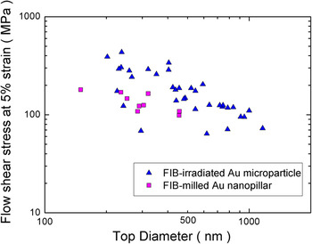
To examine the reasoning above, the flow stresses at 5% strain of FIB-irradiated Au microparticles were compared with those of Au nanopillars. It is typically difficult to define the yield strength of Au nanopillars because it is not easy to find the true initial strain burst from the stress–strain curves due to the machine noise or very small strain bursts at the early stage of deformation. Thus, we used the flow stress rather than the yield strength here for comparison. Here, we hypothesize that the underpinning mechanism for the size effect for the FIB-irradiated Au microparticle and Au nanopillars is dislocation starvation/surface nucleation for the early stage of deformation, as discussed above. The size of both samples is in the submicrometer range, and there are very few initial mobile dislocations. Thus, the flow stress of both samples would be governed by the critical stress for dislocation nucleation at the FIB-damage layers near the top surface, due to the tapered geometries of both samples.Reference Greer and Nix15 The flow stresses of both samples were calculated in the same way as the load divided by the top area. So, it would be appropriate to compare the flow stresses of Au microparticles with those of Au nanopillars. Figure 7 shows that the flow stresses at 5% strain of FIB-milled Au nanopillars are within the range of the data of FIB-irradiated Au microparticles. Thus, the ion dose condition in this study produces an effect that is similar to that in processing of Au nanopillars.
The flow shear stress at 5% strain as the function of sample top diameter for the FIB-milled Au microparticle and the FIB-milled Au nanopillars.

Note that the flow stresses for microparticles at 5% strain clearly show a size effect. By contrast, for the case of the yield strength in Fig. 6, the scatter is so large that any size effect would be buried in the scatter of the data. In micropillar plasticity, the strain hardening rate of small microparticles is higher than that of large ones. Thus, the flow stress of smaller microparticles is higher than that of larger ones at 5% strain. As a result, the size effect for the flow stress at 5% strain is more visible than that of for the yield strength. In fact, the yield strength of FIB-irradiated microparticles should also depend on the ion dose. As a future study, it would be worthwhile to study the effect of ion dose systematically. Auger electron spectroscopy would also be desirable to quantify the amount of Ga+ ion implantation.Reference Greer and Nix15
B. The effects of prestraining and prestraining/FIB irradiation
The similarity of the stress–strain curves for prestraining and prestraining/FIB irradiation indicates that FIB irradiation does not alter the mechanical properties of Au microparticles with preexisting mobile dislocations. There are some possible hardening mechanisms that could be associated with FIB irradiation: solid solution hardening, precipitation hardening, and amorphous layer hardening.Reference Kiener, Motz, Rester, Jenko and Dehm5 However, our results show that these potential hardening effects are not significant even at the submicron scale, where the volume fraction of damage layer is not negligible. Whereas the whole side surface of micropillars is FIB-milled, only the top half of the surface of microparticles was exposed to the Ga+ ion beam due to the sphere-like geometry. Nevertheless, the half fraction of area is large enough for mobile dislocations to interact with the damage layers. Thus, the various defects at the free surface may not effectively prevent the escape of mobile dislocations.
Our results are also consistent with former studies. Greer and Nix intentionally reduced the amount of implanted Ga atoms using argon plasma etching and found that the flow strength of Au micropillars did not change after argon plasma etching.Reference Greer and Nix15 Also, El-Awady et al. performed parametric studies of the effects of precipitates using dislocation dynamics and found a negligible effect on the size–strength scaling law.Reference El-Awady, Woodward, Dimiduk and Ghoniem18 These studies support our conclusion that once the dislocation network forms in the volume, its evolution is not affected significantly by the presence of the FIB damage layer even at the submicron scale. In this study, however, dislocation structures of prestrained Au microparticles are not examined in detail. For a rigorous study, the evolution of dislocation structures needs to be studied for the different amount of prestraining. Transmission electron microscope images would be desirable to understand the effects of prestraining on the formation of a bulk dislocation source.
V. CONCLUDING REMARKS
We have studied the effects of FIB irradiation and/or prestraining on the mechanical properties of nearly defect-free Au microparticles on a sapphire substrate. Whereas a pristine Au microparticle yields near at the theoretical strength and shows a huge strain burst, the FIB-irradiated microparticles showed a dramatic reduction of the yield strengths and jerky stress–strain curves. These results imply that the existence of FIB damage layer facilitates the dislocation nucleation at the free surface and that the dislocation sources are intermittently operated. According to the SRIM calculation and simple analysis, the ion dose condition in this study is similar to that of the typical micropillar production. As a consequence, the flow stresses at 5% strain of microparticles are similar with those of micropillars. Furthermore, a nanohammering method allowed us to prestrain Au microparticles by 10–40% height reduction, and the significant decreases of yield strengths were observed, along with jerky stress–strain curves. However, FIB irradiation does not alter the stress–strain behavior of prestrained Au microparticles, which contain mobile dislocations. The motion of preexisting mobile dislocations would not be affected significantly by the various defects created by FIB radiation even at the submicron scale.
ACKNOWLEDGMENTS
S-W. Lee and W.D. Nix were supported by the Office of Science, Office of Basic Energy Sciences of the U.S. Department of Energy under Contract No. DE-FG02-04ER46163. D. Mordehai was supported in part by a Fine Fellowship. Partial support of the Russell Berry Nanotechnology Institute at the Technion is heartily acknowledged.
APPENDIX
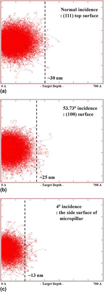
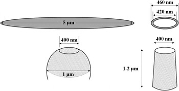
We used the Stopping and Range of Ions in Matter (SRIM) simulation to study the penetration depth and the number of implanted Ga+ ions. According to the SRIM calculation, the penetration depths of Ga+ ion beam are ∼30 nm for {111} plane and ∼25 nm for {100} plane for Au microparticles. Figure A1 shows that the penetration depth at 4° incidence (the side surface of micropillars) is about one-third of penetration depth at 90° incidence (the top surface of microparticles). The simulation results also provide the number of implanted and backscattered ions. For a given number of applied ions, the total number of implanted ions for the normal incidence is about three times higher than that of 4° incidence. Thus, our microparticle appears to be more damaged than the micropillar. However, we have to consider the current density of the beam since we used the large circular pattern to reduce the current density. The schematic in Fig. A2 shows the geometry of micropillar and microparticle for the calculation of current densities. Suppose that the Au microparticle with a top diameter of 400 nm and a central diameter of 1 μm is exposed to the 10 pA beam for 7 s. Since we used a 5-μm diameter circular pattern, the current density of the beam is (10 pA)/ (π × (2.5 μm)2) = 0.51 C/(m2 s). Then, the total dose of Ga+ ions per unit area can be obtained by multiplying the current density by the beam exposure time. So, the total dose per unit area is (0.51 C/(m2 s))/(1.6 × 10−19 C) × (7 s) = 2.23 × 10¹⁹ ions/m2 for 7 s. Assume that the concentric circular pattern is used for the micropillar with D ∼ 400 nm, a similar top diameter. For the final milling process, suppose that the inner diameter of concentric pattern is 420 nm and the outer diameter is 460 nm. In this case, the current density is (10 pA)/[π × ((230 nm)2 − (210 nm)2)] = 362 C/(m2 s). For 1 s final thinning, the total ion dose per unit area is 362 C/(m2 s)/(1.6 × 10−19 C) × (1 s) = 2.3 × 10²⁰ ions/m2 for 1 s.
Suppose that the spherical shape of microparticle with the top and center diameters of 400 nm and 1 μm, respectively. Then, the side surface area, which is exposed to FIB, can be obtained by subtracting the cap area from the area of hemisphere. The beam exposed area of microparticle is the sum of the top surface and the side surface, which is π(200 nm)2 + [2π(500 nm)2− π((200 nm)2 + (42 nm)2)] = 1.57 × 10⁶ nm2. In the case of pillar geometry with the same top diameter of 400 nm, let us assume that the aspect ratio (L/D) is three, there is no tapering, and only the side surface is exposed to FIB. Then, the side surface area is 2π(200 nm)(3 × 400 nm) = 1.51 × 10⁶ nm2. Thus, the beam exposed area is similar for the both geometries. Consequently, for the given top diameter, the ion dose of micropillars is about 10 times higher than that of microparticles due to the 10 times higher current density and the similar surface area. Here, the calculations were done for D ∼ 400 nm, but even for the different diameters, the difference in beam exposed areas does not differ significantly.
Results of Stopping and Range of Ions in Matter (SRIM) calculations for 30 keV Ga ion implantation into pure Au at (a) glancing incidence (35.3°) for the {100} top plane, (b) normal incidence (90°) for the {111} top plane, and (c) glancing incidence (4°) for the side surface of nanopillar. The total 10,000 ions collided with the gold surface in these simulations.

The schematic of the Au microparticle and the Au nanopillar with a top diameter of 400 nm for the calculation of the total ion doses. The dimensions of ion-beam patterns are shown above samples. The shaded areas are the surfaces which are exposed to Ga+ ion beam.