1. INTRODUCTION
The enhancement of microwave power density at a certain distance is one of most significant problems in the development and application of high power microwave (HPM) technology. There are many devices whose outputs reach GW levels (Zhang et al., Reference Zhang, Zhong, Jin, Shu, Cao and Zhou2009, Reference Zhang, Jin, Yang, Zhong, Shu, Zhang, Qian, Yuan, Li, Fan, Zhou and Xu2011; Gao et al., Reference Gao, Qian and Ge2011; Cao et al., Reference Cao, Zhang and He2009; Xiao et al., Reference Xiao, Zhang, Zhang, Li, Zhang, Song, Hu, Sun and Huo2010; He et al., Reference He, Cao, Zhang, Wang and Ling2011; Gold et al., Reference Gold and Nusinovich1997; Eltchaninov et al., Reference Eltchaninov, Korovin, Rostov, Pegel, Mesyats, Rukin, Shpak, Yalandin and Ginzburg2003; Korovin et al., Reference Korovin, Kurkan, Loginov, Pegel, Polevin, Volkov and Zherlitsyn2003). Whereas the increase of the power of these deices is limited by the power capacity and radio frequency breakdown problems (Zhang et al., Reference Zhang, Zhong, Jin, Shu, Cao and Zhou2009, Reference Zhang, Jin, Yang, Zhong, Shu, Zhang, Qian, Yuan, Li, Fan, Zhou and Xu2011). The spatial power combining is a feasible approach that the frequency and phase difference among the microwave sources should be the same. The relativistic klystron amplifier (RKA), of high power, high efficiency, and steady amplitude and phase, is one candidate for the microwave power combining source (Friedman et al., Reference Friedman, Krall, Lau and Serlin1988, Lau et al., Reference Lau and Friedman1990). However, scaling the RKAs to higher frequencies (such as X-band) results in lower power and efficiency. The relation between the output power P and the microwave frequency f can be described as P × f −2 (Friedman et al., Reference Friedman, Pasour and Smithe1997). The triaxial klystron amplifier (TKA) was proposed by Naval Research Laboratory (NRL) to overcome the limitations mainly resulting from a finite geometry in the relativistic klystron amplifier (RKA) at higher frequencies (such as X-band) (Serlin et al., Reference Serlin and Friedman1994; Friedman et al., Reference Friedman, Pasour and Smithe1997; Pasour et al., Reference Pasour, Smithe, Friedman and Phillips1999, Reference Pasour, Smithe, Ludeking, Gold and Nusinovich2003). The TKA usually has a large inner conductor to enhance the power capacity as long as the inner and outer walls are close enough to the cut-off operation mode. Therefore, the design and optimization is a time-consuming process in the particle-in-cell (PIC) simulation. The theory investigation is an effective approach to shorten the design duration. We have developed an improved small-signal theory on beam-cavity interaction based on the transmission line model of space charge waves and the theory of Krall and coworkers (Qi et al., Reference Qi, Zhang, Zhong, Zhang, Bai, Zhang and Bai2012). The improved small-signal theory can predict the first-order harmonic current well by which the optimal position of the buncher cavity can be confirmed. However, the small-signal theory will lose its effectiveness when the modulation voltage exceeds a certain value that is usually less than one-tenth of the beam voltage. Namely, the improved small-signal theory can not guide the position of the output cavity for the interaction between the beam and the buncher cavity is a nonlinear and large-signal process. Therefore, there is a need to develop a large-signal theory for the TKA to describe the bunching of a beam after interacting with a buncher cavity.
There have been many theoretical works investigating propagation of the large-signal theories of RKAs (Wallander, Reference Wallander1968; Paul, Reference Paul1971; Uhm, Reference Uhm, Park and Armstrong1993, Reference Uhm1997; Friedman et al., Reference Friedman, Krall, Lau and Serlin1988). Although the theories of RKAs are no longer reasonable in the TKA for the introduction of inner conductor changes the boundaries that an intense relativistic electron beam (IREB) will experience, the thoughts and methods are still available. Among the large-signal theory of RKAs, the theory developed by NRL is significant for it gives an analytical expression of the harmonic current and there is no need to program a code to update the harmonic current and the velocity time by time. We will adopt the similar method to develop the large-signal theory of bunching in the TKA. Whereas the NRL's theory can give the bunching current of an IREB with velocity modulation only, it does not give out the transient velocity in the bunching process and can not dispose the bunching problems of an IREB with both velocity and density modulation. Namely, the NRL's theory can calculate the harmonic current in an input cavity of the RKA in both the weak and strong drive case, while not for the bunching behavior after a pre-modulated beam interacting with the buncher cavity. Generally, an input cavity is driven by a weak signal that introduces small nonuniformities in the electron velocity distribution that are translated, after propagation, into density modulation. The pre-modulated IREB excites a buncher cavity downstream and build up a bigger voltage across the cavity gap that will modulate the beam further and enhance the density modulation. Therefore, a large-signal theory should also calculate the harmonic current after an IREB, with initial velocity and density modulation, interacting with a large voltage or a buncher cavity.
2. THE LARGE-SIGNAL THEORY OF BUNCHING
Assuming that an annular IREB is in a perfectly conducting coaxial drift tube, with an inner radii r i, an outer radii r o and an infinite length. We suppose that the beam is infinitely thin, of radius r b, current I 0, velocity υ 0 and guided by an infinite axial magnetic field. The electric field in the coaxial drift tube only varies on the radius r
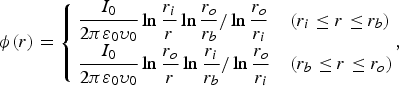 $${\rm \phi} \lpar r\rpar = \left\{\matrix{\displaystyle{{I_0 \over 2{\rm \pi} {\rm \varepsilon}_0 {\rm \upsilon}_0}} \ln \displaystyle{{r_i \over r}} \ln \displaystyle{{r_o \over r_b}} / \ln \displaystyle{{r_o \over r_i}} &\lpar r_i \leq r \leq r_b\rpar \cr \displaystyle{{I_0 \over 2{\rm \pi} {\rm \varepsilon}_0 {\rm \upsilon}_0}} \ln \displaystyle{{r_o \over r}} \ln \displaystyle{{r_i \over r_b}}/\ln \displaystyle{{r_o \over r_i}} &\lpar r_b \leq r \leq r_o \rpar}\comma \; \right.$$
where ɛ0 is the permittivity in the vacuum. From the conservation of energy, one obtains
 $${\rm \gamma}_{inj} = {\rm \gamma}_0 + I_0 /I_s {\rm \beta}_0 = {\rm \gamma}_0 + {\rm \alpha}_0 {\rm \gamma}_0^3\comma \;$$
 $\rm where \;{\rm \alpha} _0\,=\,{\rm I}_0 /\lpar {\rm I}_{\rm s} {\rm \gamma} _0^3 {\rm \beta} _0 \rpar \comma \; {\rm I}_{\rm s} \,= \displaystyle{{2{\rm \pi} {\rm m}_0 {\rm c}^3 \over {\rm e}}} \ln \displaystyle{{{\rm r}_{\rm o} \over {\rm r}_{\rm i}}}/\ln \displaystyle{{{\rm r}_{\rm o} \over {\rm r}_{\rm b}}} \ln \displaystyle{{{\rm r}_{\rm b} \over {\rm r}_{\rm i}}}\comma \; {\rm \gamma}_0 \;= \lpar 1 - {\rm \beta} _0^2\rpar ^{ - 1/2}\comma \; {\rm \beta}_0 = {\rm \upsilon}_0 /c\comma \; {\rm \gamma}_{inj} = 1 + \displaystyle{{eV_b} \over {m_0 c^2}}$, and V b are the total energy and the beam voltage at the injection, respectively. m 0, υ 0, and c are the rest mass of the electron, the electron drift velocity and the velocity of light in the vacuum, respectively.
Assuming the transient current and the transient velocity at z = z 1 are as follows, respectively,
 $$I\lpar z_1\comma \; {\rm \tau}\rpar = I_0 \left(1 + M\lpar z_1\comma \; {\rm \tau}\rpar \right)\comma \;$$
 $${\rm \upsilon} \lpar z_1\comma \; {\rm \tau} \rpar = {\rm \upsilon}_0 \left(1 + m\lpar z_1\comma \; {\rm \tau}\rpar \right)\comma \;$$
where τ is the time when an electron fluid element reaches z 1. Assuming the radius of the beam remains unchanged. According the definition of the current, the charge density at z 1 can be obtained
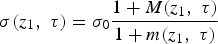 $${\rm \sigma} \lpar z_1\comma \; {\rm \tau}\rpar = {\rm \sigma}_0 \displaystyle{{1 + M\lpar z_1\comma \; {\rm \tau} \rpar \over 1 + m\lpar z_1\comma \; {\rm \tau} \rpar }}$$
where σ0 is the charge density of the un-modulated IREB.
Here we introduce a Larangian variable χ(t,τ) to represent the displacement of the electron fluid element resulting from the presence of the modulation voltage. We now introduce a long wavelength assumption under which the electric potential can be described as Eq. (1). The equation that the displace χ(t,τ) approximately satisfied can be attained as the form of the Newton's second law (Friedman et al., Reference Friedman, Krall, Lau and Serlin1988)
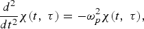 $$\displaystyle{{d^2 \over dt^2}} {\rm \chi} \lpar t\comma \; {\rm \tau}\rpar = - {\rm \omega}_p^2 {\rm \chi} \lpar t\comma \; {\rm \tau}\rpar \comma \;$$
where ωp2 = (σ(z 1, τ)/γ03) ω2 (−1 + 1/β02). Assuming the electron fluid element is modulated by a voltage Vsin(ωt) at z 1. The modulation coefficient of the velocity of the electron fluid element may be approximated as follows
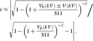 $$\eqalign{{\rm \varepsilon} &\approx \left\vert \sqrt{1 - \left(1 + {V_b \lpar kV\rpar \pm V\lpar kV\rpar \over 511} \right)^{-2}} \bigg{/} \right. \cr &\quad \left. \sqrt{1 - \left(1 + {V_b \lpar kV\rpar \over 511} \right)^{-2}} - 1 \right\vert.}$$
The sign is positive for the modulation coefficient when the modulation voltage accelerates the electron fluid element, and negative for the modulation coefficient when the modulation voltage decelerates the electron fluid element. For a narrow gap, the transmit effect may be neglected. The electron fluid element receives a velocity modulation by the modulation voltage
 $$\mathop{{\rm \chi}}\limits^{\bullet} = {\rm \varepsilon} {\rm \upsilon} \lpar {\rm \tau} \rpar \sin \lpar {\rm \omega} {\rm \tau} + {\rm \phi}_0\rpar \comma \;$$
which depends on the phase difference φ0 of the modulation voltage when the electron fluid element arrives at z 1. Apparently, the displacement of the electron fluid element introduced by the presence of the modulation voltage is zero when the beam instantaneously experiences the modulation voltage. Therefore, the displacement χ(t, τ) at the time t can be obtained by integrating Eq. (8)
 $${\rm \chi} \lpar t\comma \; {\rm \tau} \rpar = \lpar {\rm \varepsilon} {\rm \upsilon}_0 /{\rm \omega}_p \rpar \sin \lpar {\rm \omega} {\rm \tau} + {\rm \varphi}_0 \rpar \sin {\rm \omega} _p \lpar t - {\rm \tau}\rpar.$$
Thus, the position and the velocity υ (t,τ) of the electron fluid element at the time t can be obtained
 $$z\lpar t\comma \; {\rm \tau} \rpar = {\rm \upsilon} \lpar {\rm \tau} \rpar \lpar t - {\rm \tau} \rpar + \lpar {\rm \varepsilon} {\rm \upsilon} _0 /{\rm \omega}_p \rpar \sin \lpar {\rm \omega} {\rm \tau} + {\rm \phi}_0\rpar \sin {\rm \omega}_p \lpar t - {\rm \tau}\rpar \comma \;$$
 $${\rm \upsilon} \lpar t\comma \; {\rm \tau} \rpar = {\rm \upsilon} \lpar {\rm \tau} \rpar + {\rm \varepsilon} {\rm \upsilon}_0 \sin \lpar {\rm \omega} {\rm \tau} + {\rm \phi}_0 \rpar \cos {\rm \omega}_p \lpar t - {\rm \tau} \rpar.$$
According the law of charge conservation before and after the beam being modulated
 $$I_{\rm I} \lpar z_1\comma \; {\rm \tau} \rpar d{\rm \tau}=I_{{\rm II}} \lpar z\comma \; t\rpar dt.$$
One obtains the transient current at z
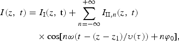 $$\eqalign{I\lpar z\comma \; t\rpar &= I_{\rm I} \lpar z\comma \; {\rm t}\rpar + \sum_{n = - \infty}^{+\infty} I_{{\rm II}\comma n} \lpar z\comma \; t\rpar \cr &\quad \times \cos \lsqb n{\rm \omega} \lpar t - \lpar z - z_1 \rpar / {\rm \upsilon} \lpar {\rm \tau} \rpar \rpar + n{\rm \varphi}_0\rsqb \comma \; }$$
where
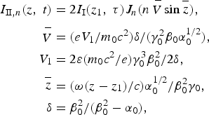 $$\eqalign{I_{{\rm II}\comma n} \lpar z\comma \; t\rpar &= 2I_{\rm I} \lpar z_1\comma \; {\rm \tau}\rpar J_n \lpar n\mathop{V}\limits^{-} \sin \mathop{z}\limits^{-}\rpar \comma \; \cr \mathop{V}\limits^{-} &= \lpar eV_1 / m_0 c^2\rpar {\rm \delta} / \lpar {\rm \gamma}_0^2 {\rm \beta}_0 {\rm \alpha}_0^{1/2}\rpar \comma \; \cr V_1 &= 2{\rm \varepsilon} \lpar m_0 c^2 /e\rpar {\rm \gamma} _0^3 {\rm \beta}_0^2 /2{\rm \delta}\comma \; \cr \mathop{z}\limits^{-} &= \lpar {\rm \omega} \lpar z - z_1\rpar / c\rpar {\rm \alpha}_0^{1/2}/ {\rm \beta}_0^2 {\rm \gamma}_0\comma \; \cr {\rm \delta} &= {\rm \beta}_0^2 / \lpar {\rm \beta}_0^2 - {\rm \alpha}_0\rpar \comma \; }$$
and J n is the Bessel functions on the order of n. The current of the beam when it arrives at z 1 can also be described as follows
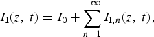 $$I_{\rm I} \lpar z\comma \; t\rpar = I_0 + \sum_{n = 1}^{+ \infty} I_{{\rm I}\comma n} \lpar z\comma \; t\rpar \comma \; $$
where I 1,n (z 1, τ) is the transient harmonic current at z 1 and time τ. Form Eq. (14), the total n-th harmonic current can be obtained that contains the n-th harmonic currents brought by the first and second modulation voltages.
 $$I_n \lpar z\comma \; t\rpar = I_{{\rm I}\comma n} \lpar z\comma \; t\rpar + I_{{\rm II}\comma n} \lpar z\comma \; t\rpar .$$
Eqs. (10), (11), and (15) are the results of the large-signal theory of bunching in the TKA that describe the position and the velocity of the electron fluid element and the n-th harmonic current of the beam, respectively.
3. VERIFICATION OF THE LARGE-SIGNAL THEORY BY PIC SIMULATION
3.1. Bunching of an IREB with Velocity Modulation Only
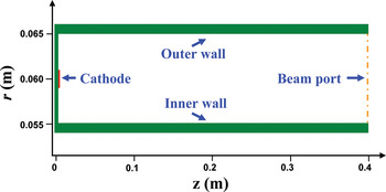
The velocity-modulated IREB propagates through a coaxial drift tube where the velocity non-uniformity will be transformed into density non-uniformity in the TKA. Therefore, the large-signal theory of bunching of the IREB with velocity modulation only can be verified in a coaxial tube. Figure 1 presents the coaxial tube in the simulation, left of which locates an annular cathode and right of which is open for the beam. The beam voltage is modulated at the injection as follows
 $$V = V_b + V_1 \sin \lpar {\rm \omega} t\rpar \comma \;$$
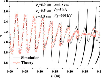
where the modulation voltage V 1 is on the order of magnitude with the beam voltage. The transient relativistic factor of the beam varied drift distance is attained by PIC codes (see Fig. 2). The theory results calculated by Eqs. (10) and (11) are also presented in Figure 2. The simulation and theory results are well consistent at the primary stage and begin to vary when the electron overtaking happens. In the theory calculation, we consider a certain number N of the electron during certain time Δt and investigate the bunching characteristic of these electrons. The density of the circles in Figure 2 represents the density of the electrons. However, the electrons not in the Δt will enter the calculation due to the electron overtaking phenomenon. Namely, there will be more numbers (>N) of electrons in the duration actually that will influence the behaviors of the electrons in the calculation duration, and we do not consider this influence in the theory derivation. Therefore, the difference between the simulation and the theory increases when the electron overtaking happens.
(Color online) A coaxial tube.

(Color online) The transient relativistic factor.

The first-order harmonic current attained by the theory and PIC simulation are shown in Figure 3a. The theoretic results are well in agreement with the simulation results, especially at the ascent stage. However, the optimum drift distance and the maximum value vary with numerical results when the modulation voltage exceeds about half the beam voltage, for there is strong electron-overtaking on the beam. In the theory, we assume that the charge of the electrons keeps unchanged in an arbitrary duration in deriving the harmonic current. Namely, the theory can not well predict the harmonic current when the electron overtaking occurs. It can be seen that the electron overtaking occurs at z ≈ 0.15 m in Figure 2 and the difference of the first-order harmonic current between the simulation and theory increases rapidly at about the same place in Figure 3a when the modulation voltage is 200 kV. Figure 3b shows the compare of the second-order harmonic current obtained by the theory and PIC simulation. The theory is shown to agree well with the PIC simulations at the ascent stage of the second-order harmonic current, whereas the optimum drift distance and the maximum value vary much with numerical results. In this theory, the velocity-modulation is directly expressed by the voltage modulation, and the velocity-modulation coefficient is linearly approximated as Eq. (9). Nevertheless, the velocity-modulation coefficient should contain high-order terms. The second-order term may be treated as a linear modulation at a higher frequency that equals to two times the modulation frequency of the modulation voltage. Therefore, the second-order term of the velocity-modulation coefficient will play a role in the second-order harmonic current. Whatever, we mainly concern the first-order harmonic current which will directly influence the generation of high power microwave, and the theory can well accomplish this task.
(Color online) The normalized harmonic current with velocity modulation only. (a) First-order harmonic current (b) Second-order harmonic current.

3.2. Bunching of the IREB with both Velocity and Density Modulation
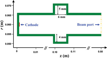
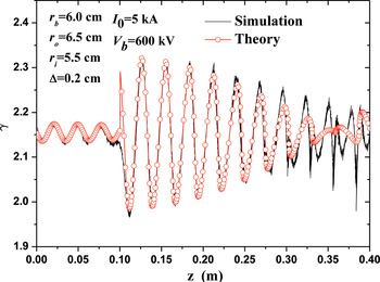
The interaction between a modulated IREB and a buncher cavity is a nonlinear and large-signal process, thus the large-signal theory can be verified by the PIC simulation of a buncher cavity. A buncher cavity, of resonance frequency 9.4 GHz, is modeled as shown in Figure 4. An IREB, of the beam current 5 kA, the beam voltage 600 kV, is emitted from the annular cathode, and then drifts a distance before entering the buncher cavity. At the injection, the beam is modulated by a voltage that is assumed to have an implicit time dependence of V 1sin(2πft). The initial modulation voltage V 1 and frequency f are set to 10 kV and 9.4 GHz to equivalent the situation of an X-band input cavity. As presented in Figures 5 and 6, the beam receives an initial velocity modulation at the injection and then drifts in the coaxial tube where the velocity non-uniformity transforms into the density non-uniformities. The beam obtains both the velocity and density modulation before entering the buncher cavity. The pre-modulated beam will excite the buncher cavity and induces a voltage V 2 across the gap of the cavity which will modulate the beam further.
(Color online) A buncher cavity with coaxial tube.

(Color online) The transient relativistic factor of an IREB with both velocity and density modulation.

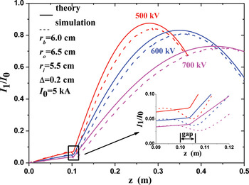
(Color online) The normalized first-order harmonic current of an IREB with both velocity and density modulation.

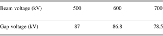
As shown in Figure 5, the transient relativistic factor calculated by the theory is in compliance with the simulation result. The modulation voltage V 2 in the theory is obtained by the PIC codes (see Table 1). The phase difference φ0 in Eq. (8) is assumed to be 0.34 π. Namely, there is a phase difference in the voltage of the buncher cavity excited by a modulated beam which may be obtained by the theory of Uhm (Reference Uhm, Park and Armstrong1993). As shown in Figure 5, the electrons should have been accelerated at the position of the buncher cavity while they decelerate inversely which may result from the phase difference of the voltage of the cavity.
The voltage of the outer gap of the buncher cavity at different beam voltage.
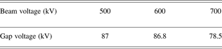
Figure 6 presents the first-order harmonic current with different beam voltages obtained by the simulation and the theory. The modulation voltage V 2 at different beam voltages in the theory is replaced by the voltage of the outer gap of the buncher cavity that is obtained in the simulation (see Table 1). The results are all obtained in the steady state and without consideration of the transient behavior of the buncher cavity. In the theory, the gap of the cavity is assumed to be infinite narrow that could not be in practice. Therefore, the position of the buncher cavity for the theory is set to be 13 mm, which is the coordinate of the middle of the buncher cavity actually. The theoretic results are well consistent with the simulation results that they have approximate optimum drift distance and maximum value, even at the descend stage. Whereas the theoretic results are about 8% bigger than the simulation results at the ascend stage, and the first-order harmonic current in the simulation slightly decreases at the beam entering the buncher cavity and then quickly increases as the propagation distance increases. In the derivation of the harmonic current, we have considered the phase difference φ0 between the induced voltage of the cavity and the velocity-modulated beam. It concludes that the bunching current depends on the phase difference. Namely, the phase difference will influence the harmonic current after the beam interacting with the modulation voltage. It can be seen that the electrons decelerate at the position of the buncher cavity and influence the modulation phase to the beam by the cavity (see Fig. 5). It may be noted that the phase difference mainly influence the current and velocity characteristic of the beam obtained by the previous modulation voltage or the previous cavity and do not affect the harmonic current generated by this cavity. Therefore, According to Eqs. (13) and (15), the first-order harmonic current after the beam interacting with the buncher cavity may be improved further as follows
 $$I_n \lpar z\comma \; t\rpar =I_{{\rm I}\comma n} \lpar z\comma \; t\rpar \cos \lpar n{\rm \varphi} _0 \rpar +I_{{\rm II}\comma n} \lpar z\comma \; t\rpar .$$
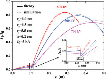
The normalized first-order current is calculated according the formula above and the phase difference is set to be 0.34 π to coincide with the assumption when calculating the transient relativistic factor. As shown in Figure 7, the improved theoretic results are almost perfectly agreement with the simulation results and it may be proved that the assumption of phase difference between the induced voltage of the buncher cavity and the beam is rational and self-consistent.
(Color online) The normalized first-order harmonic current calculated by the improved theory.

4. CONCLUSION
This paper extends the nonlinear theory of the RKA developed by NRL to the TKA situation. Further, we analyze the bunching behavior, including the harmonic current and the transient velocity, of an IREB with both velocity and density modulation. Additionally, the theory expresses the velocity modulation directly by the voltage modulation which is easier to be attained and controlled in practice. Consequently, the large-signal theory of bunching in this paper could deal with more general situations such as the bunching of a modulated IREB after interacting with a buncher cavity of the TKA. We perform a few checks on the large-signal theory by PIC simulation. We firstly simulate an IREB with a voltage modulation propagating in a coaxial tube. It is noted that the theory can predict the first-order harmonic current well but not for the second-order harmonic current. We secondly simulate the bunching of an IREB, with both velocity and density modulation, after interacting with a buncher cavity. The theoretic results are well in agreement with the simulation results, whereas the theoretic results are about 8% bigger than the simulation results at the ascend stage. A conceivable improved theory is discussed lastly and it may conclude that the improved theory can decrease the difference between the results obtained by the theory and the simulation.
This paper is a primary investigation on the bunching of a beam in the TKA, and it should be developed further, including improvement of the large-signal theory, transient analysis of the buncher cavity excited by a pre-modulated IREB, description of the interaction between an IREB and a buncher cavity and so on.
ACKNOWLEDGMENTS
This work was supported by the National High Technology Research and Development Program of China and the Outstanding Graduate-student Innovation Fund of National University of Defense Technology (Grant No. B120705).