




I. INTRODUCTION
Contrary to metals with high symmetry crystal structures in which the dislocation slip plays a dominant role in plastic deformation, for metals with low symmetry hexagonal close-packed (hcp) structures, deformation twinning strongly influences their mechanical properties. Reference Reed-Hill and Buchanan1–Reference Kelley and Hosford5 In hcp metals, except for the pyramidal slip systems, the basal and the prismatic slip systems are unable to accommodate the strain along the c-axis. Thus, all the twinning modes in hcp which provide a strain component along the c-axis are crucially important for strain accommodation.
A significant difference between the twinning modes in hcp and those twinning modes in cubic metals is that, the magnitude of the Burgers vectors of the elementary twinning dislocations (b T) is usually only a small fraction of the Burgers vector of matrix dislocations. Reference Christian and Mahajan6 Twin growth is mediated by zonal dislocations Reference Christian and Mahajan6–Reference Li and Ma10 that involve at least two twinning planes simultaneously, in contrast to twinning in cubic metals where twin growth is mediated by a partial dislocation on each twinning plane. Reference Li, Cao, Ramesh and Ma11,Reference Mahajan and Chin12 But the configurations of the zonal twinning dislocations are quite complex and their structures are not fully understood.
In face-centered-cubic metals, twinning can be accomplished by a homogeneous shear mediated by the glide of Shockley partials, without the need for any extra atomic movements. The parent atoms can be directly carried to the twin positions by the homogeneous shear. In sharp contrast, in hcp metals a homogeneous shear alone is unable to complete the twinning process and atomic shuffling is required to achieve the correct twin orientation relationship. Reference Christian and Mahajan6,Reference Li and Ma10,Reference Bilby and Crocker13 However, describing the shuffles of individual atoms in each twinning mode is non-trivial and so far no detailed analysis has been reported.
For hcp titanium (Ti) and zirconium (Zr),
 $\left\{ {11\bar 22} \right\}\left\langle {11\bar 2\bar 3} \right\rangle$
twinning mode has been observed and characterized in experiments.
Reference Rapperport14–Reference Mason, Bingert, Kaschner, Wright and Larsen17
Using interferometry, Rapperport
Reference Rapperport14
and Paton and Backofen
Reference Paton and Backofen15
measured the magnitude of the twinning shear (s) and the reported value is close to 0.22. This value leads to the conjecture that the twinning dislocation for this particular twinning mode should be a three-layer zonal, and complex shuffles must be involved, but detailed description of the shuffles were not provided.
Reference Christian and Mahajan6
For this small magnitude of twinning shear, the corresponding K
2 plane, i.e., the second invariant plane should be
 $\{ 11\bar 2\bar 4\}$
.
Reference Christian and Mahajan6,Reference Bilby and Crocker13
However, the experimentally measured magnitude of the small twinning shear (∼0.22) and the predicted
 $\{ 11\bar 2\bar 4\}$
K
2 plane cannot be verified in atomistic simulations. Using pair potential for Zr, Serra and Bacon
Reference Serra and Bacon18
studied the motion of a
 $\left\{ {11\bar 22} \right\}$
twin boundary (TB). They found that, under the shear strain, the mobile twinning dislocation only involves a single twinning plane, not the predicted three-layer zonal twinning dislocation, and the artificially constructed three-layer dislocation is immobile. The K
2 plane obtained in their simulation was the (0001) basal plane and not the
 $\{ 11\bar 2\bar 4\}$
plane. If the K
2 plane was (0001), then the magnitude of the twinning shear would be 1.26 which is so large that it was deemed unlikely according to the classical twinning theory.
Reference Christian and Mahajan6
The magnitude of any twinning shear should be smaller than unity. More recently, Li et al.
Reference Li, El Kadiri and Horstemeyer19
simulated TB migration of
 $\left\{ {11\bar 22} \right\}\left\langle {11\bar 2\bar 3} \right\rangle$
twinning by using the embedded atom method (EAM)
Reference Daw and Baskes20,Reference Daw and Baskes21
potential for Ti. Again the simulation results showed that the K
2 plane is (0001), and the twinning dislocation is not a three-layer zonal twinning dislocation. The axial ratios for Ti (1.588) and Zr (1.593) are very close, and the
 $\left\{ {11\bar 22} \right\}$
twinning mechanism should be the same. Thus, irrespective of the interatomic potentials used in the simulations, the twinning elements for this particular twinning mode predicted in the classical theory cannot be reproduced. Several puzzling issues hence arise regarding these discrepancies between the prediction of the classical theory, the experimental measurements and the atomistic simulations. It is not possible for a twinning mode to have two different K
2 planes and hence two different magnitudes of the twinning shear. If the experimentally measured value of s is accurate, then all the atomistic simulation results of
 $\left\{ {11\bar 22} \right\}\left\langle {11\bar 2\bar 3} \right\rangle$
twinning would be incorrect; if the atomistic simulations are correct, then the predicted K
2 plane and the measured twinning shear would be questionable; but another question arises: given the fact that the magnitude of any twinning shear should be less than unity, how to reconcile this conflict of the seemingly large twinning shear (s = 1.26) with the classical twinning theory?
The purpose of this work is to study the mechanism of TB migration and the TB structure of
 $\left\{ {11\bar 22} \right\}\left\langle {11\bar 2\bar 3} \right\rangle$
twinning mode, using molecular dynamics simulations. In particular, atomic shuffles were analyzed in great detail for the first time. Such an analysis is critically important for understanding any twinning mechanism in hcp, and the results obtained shed new light on deformation twinning in hcp.
II. SIMULATION METHOD
EAM type potentials
Reference Daw and Baskes20,Reference Daw and Baskes21
for Ti-Al alloys were used in the simulations in this work. These interatomic potentials were developed by Zope and Mishin.
Reference Zope and Mishin22
Using the potentials for Ti, we simulated
 $\left\{ {11\bar 22} \right\}\left\langle {11\bar 2\bar 3} \right\rangle$
twinning in Ti,
Reference Li, El Kadiri and Horstemeyer19
pyramidal dislocation slip and
 $\left\{ {10\bar 12} \right\}\left\langle {10\bar 1\bar 1} \right\rangle$
twinning, and the results were satisfactory. In this work, we use the same potentials to investigate the mechanism of
 $\left\{ {11\bar 22} \right\}\left\langle {11\bar 2\bar 3} \right\rangle$
twinning.
To construct
 $\left\{ {11\bar 22} \right\}\left\langle {11\bar 2\bar 3} \right\rangle$
twins, two single crystals were first created, and then they were bonded together such that the
 $\left\{ {11\bar 22} \right\}\left\langle {11\bar 2\bar 3} \right\rangle$
twin orientation relationship is satisfied. The system was then relaxed before an external shear strain was applied. The initial configuration of a
 $\left\{ {11\bar 22} \right\}\left\langle {11\bar 2\bar 3} \right\rangle$
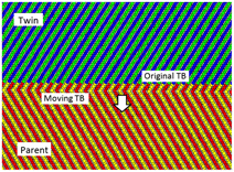
twin was shown in Fig. 1. The box size was 40 × 40 × 40 nm3, containing a total number of atoms of about 2.6 million. Figure 1 only shows a small cross-section of the twins in the simulation. The twinning plane
 $\left\{ {11\bar 22} \right\}$
and the basal planes are all perpendicular to the figure plane. The zone axis is
 $\left\langle {1\bar 100} \right\rangle$
. To track the structural evolution during TB migration, the basal planes of the twin and the parent are colored in green/blue and red/yellow, respectively, such that the …ABABAB… hcp stacking sequence is revealed. This color scheme was retained throughout the simulations and the analysis such that the lattice transformation
Reference Niewczas23
during twinning can be readily recognized. Specifically, the color scheme is very helpful in identifying what plane the parent basal plane has been transformed to. The TB is indicated by the pink block arrow pointing to the twinning direction
 ${\eta _1} = {1 \over 3}\left\langle {11\bar 2\bar 3} \right\rangle$
.
Relaxed, initial configuration of a
 $\left\{ {11\bar 22} \right\}\left\langle {11\bar 2\bar 3} \right\rangle$
twin. The mirror symmetry is well defined. The TB and the twinning direction are marked with the pink arrow. The basal planes of the parent and the twin are colored in red/yellow and green/blue, respectively, to represent the …ABABAB… stacking sequence of hcp lattices. A shear strain was applied to drive the twin grow.

A shear strain was generated by moving the atoms of the top surface at a constant displacement rate a/10,000 per time step (a is the lattice parameter of Ti, 0.29508 nm). Thus the shear strain rate in the simulation is approximately 108 per second. The temperature was maintained at 10 K during simulation. This low temperature reduces thermal noise in structural analysis. The time step size was chosen as 4.0 fs. Free surfaces were applied to all three dimensions.
III. SIMULATION RESULTS
Under the shear strain, the
 $\left\{ {11\bar 22} \right\}$
TB migrates downward, as shown in the 2-D view of the TB in Fig. 2. During migration, the TB well matches the twinning plane. The twin thickens layer by layer as the red and yellow atoms are sheared to the twin lattice. Note that, the parent basal planes (represented by the red/yellow atoms) are sheared and transformed to the basal plane of the twin (represented by the blue/green atoms). This process indicates that the K
2 plane in the simulations is indeed (0001), instead of the
 $\{ 11\bar 2\bar 4\}$
which was predicted in the classical theory.
Reference Christian and Mahajan6,Reference Bilby and Crocker13
After migration, the atoms on both sides of the TB are mirrored about the moving TB.
2-D view of migration of the
 $\left\{ {11\bar 22} \right\}\left\langle {11\bar 2\bar 3} \right\rangle$
TB under the shear strain. The TB migrates downward layer by layer. The TB coincides with the twinning plane during migration. Note that the basal planes of the parent are transformed to the basal planes of the twin, indicating that the second variant plane K
2 is (0002), not the predicted
 $\left\{ {11\bar 2\bar 4} \right\}$
.

To better understand the nature of TB migration and the twinning dislocations in
 $\left\{ {11\bar 22} \right\}\left\langle {11\bar 2\bar 3} \right\rangle$
mode, we plotted 3-D views of the structure of the interface. To plot 3-D view of the TB during TB migration, first we selected a thin slice of the system that comprises the moving TB, i.e., part of the parent and part of the twin were selected, and then the coordination number of each atom in the selected slice was calculated. This serves to reduce the computing time. Those atoms with a coordination number different than twelve were plotted as a red circle, and they are located at the TB and the free surfaces. We plotted atoms on the free surfaces and in the perfect lattice points, i.e., those with a coordination number of 12, as little blue dots such that the TB was highlighted.
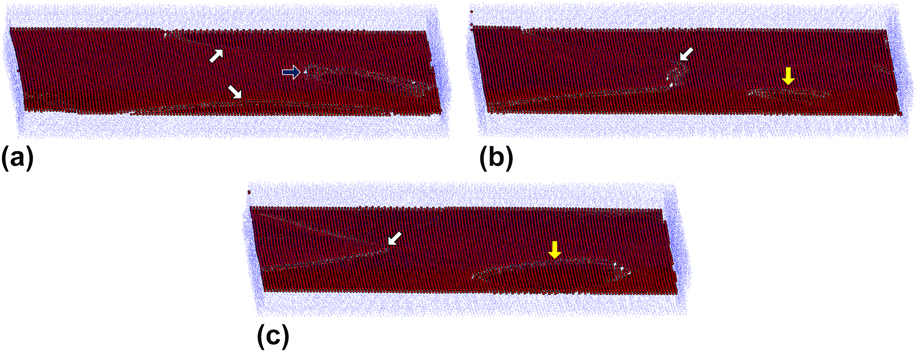
Figure 3 shows 3-D plots of twinning dislocations generated during TB migration in
 $\left\{ {11\bar 22} \right\}\left\langle {11\bar 2\bar 3} \right\rangle$
twinning. Multiple dislocations are nucleated in a single twinning plane [Fig. 3(a)]. Two dislocation lines (indicated by the white block arrows) are nucleated at the intersections of the TB and the free surfaces because these locations have higher free energies and are more favored for dislocation nucleation. These two dislocations are mostly screwed as the lines are nearly parallel to the twinning vector. Interestingly, a dislocation loop is also nucleated in the same twinning plane, along with the two dislocation lines. This loop is nucleated inside the twinning plane and expands toward the free surfaces. The two dislocation lines and the dislocation loop have the same Burgers vector. When these dislocations meet as they expand, they connect and merge into a single dislocation, as indicated by the white block arrow in Fig. 3(b). Meanwhile, a new dislocation loop (indicated by the yellow block arrow) is nucleated but in the neighboring twinning plane one layer below. The dislocations on the two neighboring twinning planes continue to glide toward the free surfaces [Fig. 3(c)]. The TB progressively migrates downward as the dislocations on each twinning plane exit to the surfaces. Note that each of these dislocation lines and loops only involves a single
 $\left\{ {11\bar 22} \right\}$
twinning plane.
3-D view of the structure of the TB of
 $\left\{ {11\bar 22} \right\}\left\langle {11\bar 2\bar 3} \right\rangle$
twinning in time sequence. Only a thin slice comprising the TB is shown. The TB is highlighted as red circles. (a) Nucleation of dislocation lines at the intersections of the TB and the free surfaces (indicated by two white block arrows). A dislocation loop (indicated by the black block arrow) is also nucleated at the TB. The dislocation lines and loop have the same twinning Burgers vector. (b) The dislocation lines glide toward each other and the dislocation loop expands. When they meet, they merge into a single dislocation (indicated by the white block arrow). Meanwhile, a new dislocation loop (indicated by the yellow block arrow) is nucleated in the neighboring twinning plane one layer below. (c) The dislocation line and the dislocation loop on two consecutive twinning planes glide in the same time, causing the TB to migrate.
IV. ANALYSIS AND DISCUSSION
The simulation results in this work reveal that the K
2 plane in the atomistic simulations is (0001) (Fig. 2) and not the predicted and widely accepted
 $\left\{ {11\bar 2\bar 4} \right\}$
.
Reference Christian and Mahajan6
During twin growth, the glide of twinning dislocations mediates the migration of the TB, but the twinning dislocations are not the predicted three-layer zonal. The twinning dislocations are nucleated as loops at the TB. Recently, Li et al.
Reference Li, El Kadiri and Horstemeyer19
simulated
 $\left\{ {11\bar 22} \right\}\left\langle {11\bar 2\bar 3} \right\rangle$
twinning in a relatively small box size and observed paired arcs of extended zonal dislocations with the magnitude of Burgers vectors of ∼0.08 nm. The two partials have Burgers vectors
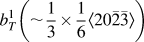 $b_T^1\left( { \sim {1 \over 3} \times {1 \over 6}\left\langle {20\bar 2\bar 3} \right\rangle } \right)$
and
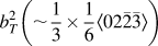 $b_T^2\left( { \sim {1 \over 3} \times {1 \over 6}\left\langle {02\bar 2\bar 3} \right\rangle } \right)$
, respectively, but the partials add up to an overall Burgers vector:
 $b_T^1 + b_T^2 \to 2{b_T}\left( { \sim {1 \over 3} \times {1 \over 3}\left\langle {11\bar 2\bar 3} \right\rangle } \right)$
. It was anticipated that the paired arcs would become dislocation loops if the box size is sufficiently large as in this work. These atomistic simulation results seem at odds with the predicted three-layer twinning dislocations.
Reference Christian and Mahajan6
Li et al.
Reference Li, El Kadiri and Horstemeyer19
showed that the magnitude of the twinning dislocation in the simulations actually equals ∼0.08 nm, indicating that atomic shuffling is involved while the single layer twinning dislocations are gliding. If there were no shuffling, then the magnitude of the twinning dislocation should be
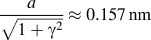 ${a \over {\sqrt {1 + {\gamma ^2}} }} \approx 0.157\,{\rm{nm}}$
, giving rise to a twinning shear of 1.26 which is unrealistically large. Thus, nearly half of the distance for a parent atom to reach the twin position is accomplished by shuffling, suggesting that only a portion of the distance is accomplished by the homogeneous shear. Because shuffling is only a local activity near the TB and makes no contribution to the twinning shear, the twinning shear for this twinning dislocation should equal b
T
/d ≈ 0.66 (d is the interplanar spacing of the twinning plane
 ${\gamma \over {2\sqrt {1 + {\gamma ^2}} }}$
), instead of 1.26. In the following, we provide a detailed analysis on the atomic shuffling involved in this particular twinning mode.
In the literature, three possible K
2 planes were reported:
 $\{ 11\bar 2\bar 4\}$
,
Reference Christian and Mahajan6,Reference Bilby and Crocker13–Reference Paton and Backofen15
(0001),
Reference Serra and Bacon18,Reference Li, El Kadiri and Horstemeyer19
and
 $\{ 11\bar 2\bar 2\}$
.
Reference Hall24
We provide analyses of shuffles for all three K
2 planes, such that comparison between these proposed twinning mechanisms can be made. According to the classical twinning theory,
Reference Christian and Mahajan6
when the K
2 plane is determined, then the twinning shear and the atomic shuffles are determined correspondingly. The choice of the K
2 plane is not necessarily unique, i.e., multiple crystallographic planes can be possible K
2 plane, but only one of them is most favorable structurally and energetically. A general, empirical criterion for the selection of the K
2 plane is “a small magnitude of twinning shear and simple shuffles”.
Reference Christian and Mahajan6
Thus, experimental measurement of the twinning shear becomes important in determining the actual K
2 plane.
A. Shuffling for
 ${{\bi K}_{\bf2}} = \{ {\bf 11}\bar {\bf 2}\bar {\bf 4}\}$

The concept of linear mapping in the classical twinning theory makes it possible to analyze atomic shuffles in any twinning mode. During twinning, the homogeneous shear maps the parent lattice to the twin lattice by transforming a direction/plane of the parent to a direction/plane of the twin, linearly. Thus, a one-to-one lattice correspondence can be established between the parent and the twin. It is worth noting that this linear mapping requires the K
1 and the K
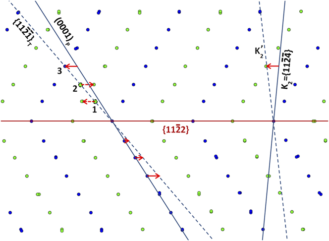
2 planes to be invariant during twinning. First, we analyze the shuffles in the plane of shear. The documented twinning shear [s ≈ 0.22 (Refs. Reference Christian and Mahajan6, Reference Rapperport14, and Reference Paton and Backofen15)] would have a Burgers vector of the elementary twinning dislocation s·d ≈ 0.027 nm on each twinning plane when a homogeneous shear takes place. This process is shown in Fig. 4 in which the basal planes of the twin (the top crystal) and the parent (the bottom crystal) are colored in green/blue alternately. To the right of the diagram, the
 ${K_2} = \left\{ {11\bar 2\bar 4} \right\}$
and the corresponding
 $K_2^\prime$
are shown. The red arrow between them represents the magnitude of the Burgers vector (0.082 nm) and this dislocation must comprise three consecutive
 $\left\{ {11\bar 2\bar 4} \right\}$
planes and hence is a three-layer zonal dislocation to reduce the twinning shear, as suggested by Christian and Mahajan,
Reference Christian and Mahajan6
Mendelson
Reference Mendelson9,Reference Mendelson25
and Kronberg.
Reference Kronberg26
To the left of the diagram, a parent basal plane is experiencing the homogeneous shear. Since a homogeneous shear must be an affine shear,
Reference Christian and Mahajan6
the basal plane must experience the same homogeneous shear as does the K
2 plane. Preferably the atoms on the parent basal plane would be sheared to the twin lattice; however this cannot be accomplished by the homogeneous shear. The three red arrows below the
 $\left\{ {11\bar 2\bar 4} \right\}$
twinning plane represent the homogeneous shear and the shortest arrow has a magnitude of 0.027 nm, which is extremely small (less than one 10th of the lattice parameter a). After the homogeneous shear, the atoms of the parent basal plane are sheared to the positions marked as 1, 2 and 3 in the twin along the dashed line which is the trace of the
 $\left\{ {11\bar 2\bar 1} \right\}$
plane of the twin, but only Position 3 is right at the twin lattice. Positions 1 and 2 are shown by the dashed circles filled with green. It is clear that complex shuffles are required for atoms in Positions 1 and 2 to reach the twin lattice, because crystallographically one parent basal plane must split into three consecutive
 $\left\{ {11\bar 2\bar 1} \right\}$
planes of the twin, as shown in Fig. 4. For Position 1, the atom must shuffle toward the left with a magnitude of about three times that of the shear (∼0.027 nm). For Position 2, the atom must shuffle opposite to position 1, i.e., toward the right. These shuffles are indicated by the dashed red arrows. Christian and Mahajan
Reference Christian and Mahajan6
pointed out that “rather complex” shuffles are needed for this twinning mode if K
2 is
 $\left\{ {11\bar 2\bar 4} \right\}$
.
Complex atomic shuffling is required for
 $\left\{ {11\bar 22} \right\}\left\langle {11\bar 2\bar 3} \right\rangle$
twinning if the K
2 plane is
 $\left\{ {11\bar 2\bar 4} \right\}$
. To the right, the K2 and the K’
2 are marked with a solid and a dashed line. To the left, a basal plane of the parent (the solid line) is sheared to the
 $\left\{ {11\bar 2\bar 1} \right\}$
plane of the twin (the dashed line) after a homogeneous shear, which is marked by three solid arrows below the twinning plane. However, the homogeneous shear cannot carry all the atoms to the twin lattice. As indicated by the two dashed arrows, after the homogeneous shear, the atom at Position 1 must shuffle to the left with a magnitude about three times the shear. The atom at Position 2 must shuffle to the right with a magnitude larger than the shear. After the shuffling, the atoms on the parent basal plane now reside on three consecutive
 $\left\{ {11\bar 2\bar 1} \right\}$
planes of the twin. The shuffles off the plane of shear (the figure plane) are shown in Figure 5.
The maximum shuffle in the plane of shear can be approximated as the difference between the distance for an atom in the parent lattice to be carried to the twin lattice and the magnitude of elementary b
T
, and this equals
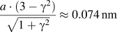 ${{a\cdot(3 - {\gamma ^2})} \over {\sqrt {1 + {\gamma ^2}} }} \approx 0.074\,{\rm{nm}}$
, which is about triple the magnitude of Burgers vector of the elementary twinning dislocation. But these complex shuffles are not enough because shuffles off the plane of shear are required as well. The shuffles in the direction perpendicular to the plane of shear are analyzed below.
The shear and shuffle in the plane of shear cannot completely transform the basal plane of the parent to the
 $\left\{ {11\bar 2\bar 1} \right\}$
plane of the twin. As shown in Fig. 5, the atomic shuffles off the plane of shear are complex too, if the K
2 plane is
 $\left\{ {11\bar 2\bar 4} \right\}$
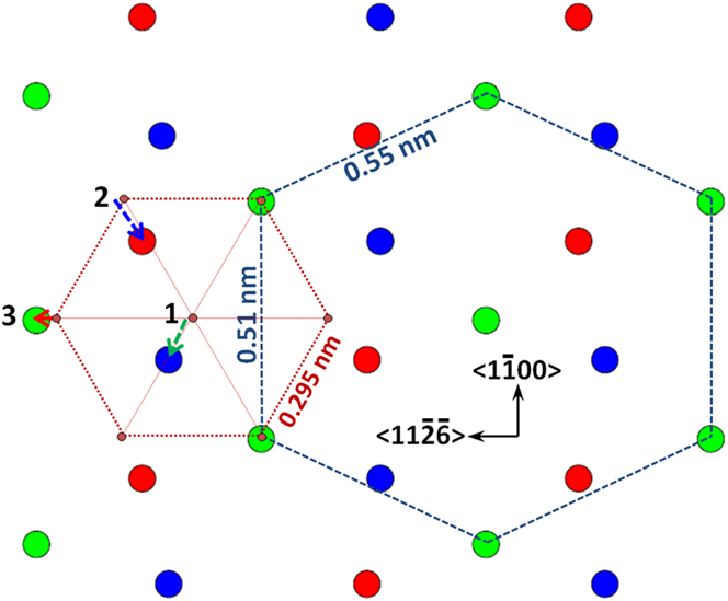
. In Fig. 5, the projection view of three consecutive
 $\left\{ {11\bar 2\bar 1} \right\}$
planes (red/green/blue) of the twin along the normal direction is shown. A basal hexagon delineated by the dotted lines which connect the smaller circles filled with red is superimposed with the green
 $\left\{ {11\bar 2\bar 1} \right\}$
plane. The shuffling components in the
 $\left\langle {1\bar 100} \right\rangle$
direction can now be revealed. For position 3, the parent atom can be sheared to the twin position directly (indicated by the solid red arrow). For position 1, a large shuffle (indicated by the dashed green arrow) is required with a component perpendicular to the η1, i.e., along
 $\left\langle {1\bar 100} \right\rangle$
. For position 2, a similar component (indicated by the dashed blue arrow) is required as well. But the component in the twinning direction is opposite (also shown in Fig. 4). Note that these shuffles are much larger than the magnitude of the Burgers vector of the elementary twinning dislocation. Together with the shuffles shown in Fig. 4, the basal plane must undergo prohibitively complex shuffles to be reconstructed into the
 $\left\{ {11\bar 2\bar 1} \right\}$
planes. The atoms in position 1 and 2 must shuffle in different directions. For Position 1, the atom must have an overall magnitude of shuffle of about 0.12 nm, which is ∼4.4 times that of the magnitude of the Burgers vector of the elementary twinning dislocation (∼0.027 nm). In sharp contrast, for position 3, no shuffle is needed. Such a huge difference in shuffles at local positions makes
 $\left\{ {11\bar 2\bar 4} \right\}$
unfavorable K
2 plane for
 $\left\{ {11\bar 22} \right\}\left\langle {11\bar 2\bar 3} \right\rangle$
twinning because atoms must experience very different local energy landscape and the required, well-coordinated atomic shuffling cannot be accomplished readily.
In addition to the shuffles in the plane of shear, complex shuffles are also required off the plane of shear, if the K
2 plane is
 $\left\{ {11\bar 2\bar 4} \right\}$
for
 $\left\{ {11\bar 22} \right\}\left\langle {11\bar 2\bar 3} \right\rangle$
twinning. Projection view of three consecutive
 $\left\{ {11\bar 2\bar 1} \right\}$
planes (red/green/blue) of the twin along the normal direction is shown. A basal hexagon (the dotted lines) is superimposed with the green
 $\left\{ {11\bar 2\bar 1} \right\}$
plane, such that the shuffling components in the
 $\left\langle {1\bar 100} \right\rangle$
direction can be seen. After shear, large shuffles at Position 1 and 2 (indicated by the dashed green and blue arrows) are needed to reach the twin lattice. Together with the shuffles shown in Figure 4, the basal plane must undergo prohibitively complex shuffles to be reconstructed into the
 $\left\{ {11\bar 2\bar 1} \right\}$
planes.
B. Shuffling for
${{\bi K}_{\bf 2}} = \{ {\bf 11}\bar {\bf 2}\bar {\bf 2}\}$

Although
 $\left\{ {11\bar 2\bar 4} \right\}$
was predicted to be the K
2 plane of
 $\left\{ {11\bar 22} \right\}\left\langle {11\bar 2\bar 3} \right\rangle$
twinning because the corresponding twinning shear is small
Reference Christian and Mahajan6,Reference Bilby and Crocker13
despite the complex shuffles, alternative K
2 plane was proposed.
Reference Christian and Mahajan6
Hall
Reference Hall24
proposed that
 $\left\{ {11\bar 2\bar 2} \right\}$
can be the reciprocal of itself. This K
2 plane has a twinning shear s = γ − γ−1.
Reference Christian and Mahajan6
For Ti, s = 0.96. This twinning shear is large although fewer atoms are involved in shuffling.
Reference Christian and Mahajan6
The analysis of the shuffles is shown in Fig. 6. To the right, the K
2 plane (indicated by the solid blue line) is homogeneously sheared to the
 $K_2^\prime$
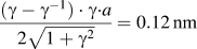
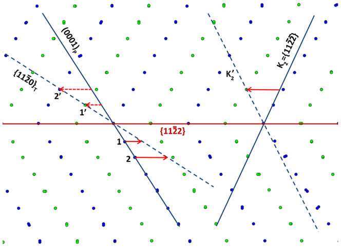
plane of the twin (indicated by the dashed blue line). The shear is indicated by the red arrow. It can be seen that the twinning dislocation would be a two-layer zonal. To the left, the basal plane of the parent (indicated by the solid blue line) experiences the same homogeneous shear. Two atoms of the basal plane were selected to show the homogeneous shear. Atom 2 is sheared to position 2′ without the need for shuffle. Atom 1 is sheared to position 1′ and shuffle is needed because positions 1 and 1′ are not on the same plane that is parallel to the plane of shear. In other words, they are on two different planes in the direction perpendicular to the figure plane. The magnitude of the shuffle is about 0.085 nm. The magnitude of the Burgers vector of the elementary twinning dislocation equals
 ${{\left( {\gamma - {\gamma ^{ - 1}}} \right)\cdot\gamma \cdot}a \over {2\sqrt {1 + {\gamma ^2}} }} = 0.12\,{\rm{nm}}$
.
Shear and shuffle in the mechanism proposed by Hall [24] in which the K
2 plane is
 $\left\{ {11\bar 2\bar 2} \right\}$
, i.e. the reciprocal of itself. In this mechanism, the twinning dislocation would be a two-layer zonal. The parent basal plane (0001)P is transformed to the
 $\left\{ {11\bar 20} \right\}$
T of the twin. Shuffle is required for atom 1 but not for atom 2. The magnitude of the twinning shear equals 0.96 for Ti.
After the shear and shuffle, the basal plane of the parent is transformed to the
 $\{ 11\bar 20\}$
plane of the twin. Although only half of the atoms are involved in the shuffling, the large twinning shear is unfavorable as well when the K
2 plane is
 $\left\{ {11\bar 2\bar 2} \right\}$
.
C. Shuffling for K 2 = (0001)
The simulation results in this work, along with other simulations
Reference Serra and Bacon18,Reference Li, El Kadiri and Horstemeyer19
reveal that the actual K
2 plane is (0001). Crystallographically, this K
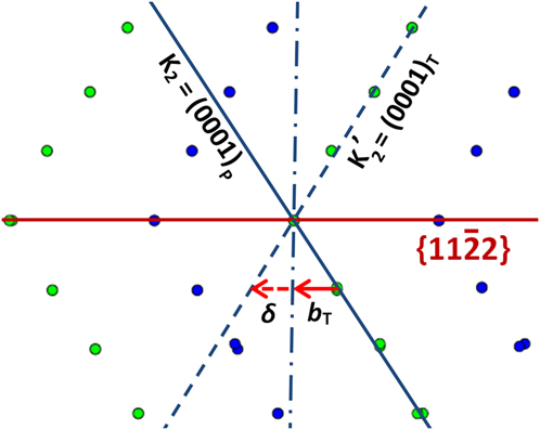
2 plane would have a nominal twinning shear s = 2/γ or 1.26 for Ti which is unrealistically large. However, as stated above, the actual twinning shear is much smaller because shuffling accounts for nearly half of the distance for a parent atom to reach the twin position during twinning. As shown in Fig. 7, the atoms of the parent basal plane, i.e., the K
2 plane, first experience a homogeneous shear with a twinning Burgers vector b
T
(indicated by the solid arrow, ∼0.08 nm), reaching an intermediate position (marked with the dash-dotted line). Then the atoms shuffle to the twin lattice with a magnitude δ ∼ 0.07 nm, as indicated by the dashed arrow. Thus the actual twinning shear equals 0.66. This process involves a homogeneous shear and much simpler shuffles than other K
2 planes. Furthermore, the twinning dislocation only involves a single twining plane and the dislocation core structure is much simpler if compared with a three-layer zonal dislocation. During lattice transformation, the basal plane of the parent is directly carried to the basal plane of the twin partly by shear and partly by shuffle. If compared to other two proposed K
2 planes (Figs. 4–6), such a twinning process with K
2 = (0001) is more favorable, because: (i) All the shuffles are inside the twinning plane
 $\left\{ {11\bar 22} \right\}$
, i.e., the K
1 plane and mostly along the twinning direction. Large shuffles off the plane of shear and in different directions are not involved; (ii) Presumably, a zonal twinning dislocation which involves more than one twinning plane and very complex shuffles may require a higher stress to nucleate and glide.
Shear and shuffle for
 $\left\{ {11\bar 2\bar 2} \right\}\left\langle {11\bar 2\bar 3} \right\rangle$
twinning as revealed in atomistic simulations. The K
2 plane is (0001), instead of
 $\left\{ {11\bar 2\bar 4} \right\}$
. First, the atoms of the basal plane of the parent experience a homogeneous shear with a twinning Burgers vector b
T (∼ 0.08 nm in the η
1), reaching an intermediate position (marked with the dash-dotted line). Then the atoms shuffle to the twin lattice with a magnitude δ ∼ 0.07 nm. The actual twinning shear equals 0.66. This process involves a homogeneous shear and much simpler shuffles.
The magnitude of the twinning shear in the simulations (s = 0.66) seems at odds with the measured value in the early experiments (∼0.22). This may be due to the accommodation effects in experiments. Rapperport
Reference Rapperport14
measured the twinning shear of
 $\left\{ {11\bar 21} \right\}$
and
 $\left\{ {11\bar 22} \right\}$
twinning modes in zirconium. It was found that s = 0.22 for
 $\left\{ {11\bar 21} \right\}$
twinning mode and s = 0.23 for
 $\left\{ {11\bar 22} \right\}$
twinning mode. But the twinning shear for
 $\left\{ {11\bar 21} \right\}$
twinning mode should be 0.64 (Ref. Reference Christian and Mahajan6), according to crystallographic calculations. Christian and Mahajan
Reference Christian and Mahajan6
suggested that “undetected accommodation effects” were responsible for the reported low value of s for
 $\left\{ {11\bar 21} \right\}$
twinning. One possible accommodation is that
 $\left\{ {11\bar 21} \right\} + \left\{ {11\bar 22} \right\}$
coupled twinning occurred in the experiments. In macroscopic tests, multiple twinning modes are activated during uniaxial compression.
 $\left\{ {11\bar 22} \right\}\left\langle {11\bar 2\bar 3} \right\rangle$
twinning is usually coupled with
 $\left\{ {11\bar 21} \right\}\left\langle {11\bar 2\bar 6} \right\rangle$
twinning during twin boundary migration. The coupled twinning (“coupled twinning” is used here to differentiate from “double twinning”) is more favorable because the overall shear strain can be significantly reduced. An example of
 $\left\{ {11\bar 21} \right\} + \left\{ {11\bar 22} \right\}$
coupled twinning is shown in Ref. Reference Serra and Bacon18. In this particular case, the basal planes of the parent, i.e., the K
2, are sheared to the
 $K_2^\prime$
of the
 $\left\{ {11\bar 22} \right\}$
twin, then these planes are sheared backward and become the
 $K_2^\prime$
of the
 $\left\{ {11\bar 21} \right\}$
twin which is also the basal. This process is possible because these coupled twins share the same zone axis
 $\left\langle {1\bar 100} \right\rangle$
. It is likely that
 $\left\{ {11\bar 21} \right\} + \left\{ {11\bar 22} \right\}$
coupled twinning occurred in the experiments and gave rise to the discounted twinning shear. Other accommodation effects such as twin-slip interaction are likely as well. By no means this analysis diminishes the value of previous experimental work, but rather, provides a plausible explanation for the discrepancy between the experiment and the atomistic simulations.
Recently, Yu et al.
Reference Yu, Shan, Li, Huang, Xiao, Sun and Ma27
conducted in-situ c-axis compression on single crystal Ti pillars that size from a few microns down to submicron. The dominant deformation mode in the pillars larger than 1.0 µm was confirmed to be
 $\left\{ {11\bar 22} \right\}\left\langle {11\bar 2\bar 3} \right\rangle$
twinning by electron backscatter diffraction and transmission electron microscopy. Large engineering strains (as large as ∼22%) were observed after compression. Large shear strains were observed on the surfaces of the specimens as well. If the K
2 plane is
 $\left\{ {11\bar 2\bar 4} \right\}$
, the maximum compressive strain produced in a specimen which is completely twinned can be calculated using the following equation
Reference Abbaschian, Abbaschian and Reed-Hill28
:
 $${\varepsilon _t} = \sqrt {1 + 2s\cdot\sin \alpha \cdot\cos \beta + {s^2}{{\sin }^2}\alpha - 1} \quad ,$$
where α is the angle between the twinning plane and the tensile axis, and β is the angle between the twinning shear direction and the tensile axis. It can be calculated that ε
t
≈ 11%, which is much smaller than the experimental values. These data support the conclusion that
 $\left\{ {11\bar 2\bar 4} \right\}$
may not be the K
2 plane for
 $\left\{ {11\bar 22} \right\}\left\langle {11\bar 2\bar 3} \right\rangle$
twinning. However, to confirm that (0001) is the real K
2 plane, more carefully designed experiments are needed.
V. CONCLUSIONS
We investigated
 $\left\{ {11\bar 22} \right\}\left\langle {11\bar 2\bar 3} \right\rangle$
twin boundary migration by using atomistic simulations. Lattice transformation during twinning was analyzed. Twinning dislocations and atomic shuffles that are required for twinning were analyzed in great detail for the first time. The following conclusions can be reached.
-
(1) The TB migration is mediated by twinning dislocations which only involve a single
$\left\{ {11\bar 22} \right\}$
twinning plane. The twinning dislocations can be nucleated as dislocation loops on the twinning plane. The second invariant plane, i.e. the K
2 plane is (0001), not
$\left\{ {11\bar 2\bar 4} \right\}$
as predicted in the classical twinning theory. -
(2) During twinning, the (0001) basal plane of the parent is transformed to the basal plane of the twin. But this lattice transformation is accomplished partly by a homogeneous shear and partly by a simple shuffle. The overall twinning shear equals ∼0.66, instead of the predicted value of ∼0.22. Thus, the conflict between the classical theory, atomistic simulations, experimental measurements, and the most recent experimental observations can be well reconciled.
-
(3) The detailed analyses on atomic shuffles for three possible K 2 planes show that if
${K_2} = \{ 11\bar 2\bar 4\}$
, very complex shuffles are required. Atoms have to shuffle in different directions with a magnitude much larger than that of the Burgers vector of the elementary twinning dislocation. This indicates that
$\{ 11\bar 2\bar 4\}$
is not a favorable K
2 plane, despite the small twinning shear. If
${K_2} = \{ 11\bar 2\bar 2\}$
, only half of the parent atoms are involved in the shuffling, but the twinning shear is so large (0.96) that
${K_2} = \{ 11\bar 2\bar 2\}$
is also unlikely. The K
2 = (0001) which was obtained in atomistic simulations is the most favorable, but caution should be exercised when the actual twinning shear is calculated and interpreted.



