



1. Introduction
Dynamo action is a magnetic instability that converts part of the kinetic energy of a moving material into magnetic energy, without the aid of a magnet, but provided of course that the material is electrically conducting (Rincon Reference Rincon2019; Tobias Reference Tobias2021). One of the simplest kinematic dynamos is the anisotropic dynamo, which relies on the anisotropy of electromagnetic properties, and for which an exponentially growing magnetic field can be generated by a velocity field as simple as a shear (Ruderman & Ruzmaikin Reference Ruderman and Ruzmaikin1984; Lortz Reference Lortz1989). Anisotropic electrical conductivity means that the electric current density  ${{\boldsymbol {J}}}$ is no longer parallel to the electric field
 ${{\boldsymbol {E}}}$, even in the absence of a velocity field
 ${{\boldsymbol {U}}}$. Similarly, an anisotropic magnetic permeability means that the magnetic field
 ${{\boldsymbol {H}}}$ and the induction field
 ${{\boldsymbol {B}}}$ are no longer parallel. In natural objects, anisotropy in electric conductivity may result, in the Earth's core from the anisotropic crystallization of the inner core (Deuss Reference Deuss2014; Ohta et al. Reference Ohta, Nishihara, Sato, Hirose, Yagi, Kawaguchi, Hirao and Ohishi2018), in plasmas from the presence of an external magnetic field (Braginskii Reference Braginskii1965) and in spiral galaxies (Brandenburg & Subramanian Reference Brandenburg and Subramanian2005) from their spiral geometries. In contrast, anisotropy of magnetic permeability seems unlikely, at least at large scale. However, at the laboratory scale, among the few experiments that succeeded in reproducing a dynamo effect, one involved soft iron (Lowes & Wilkinson Reference Lowes and Wilkinson1963, Reference Lowes and Wilkinson1968), while another worked only in the presence of soft iron propellers (Miralles et al. Reference Miralles, Bonnefoy, Bourgoin, Odier, Pinton, Plihon, Verhille, Boisson, Daviaud and Dubrulle2013; Kreuzahler et al. Reference Kreuzahler, Ponty, Plihon, Homann and Grauer2017; Nore et al. Reference Nore, Castanon Quiroz, Cappanera and Guermond2018), highlighting the crucial role that magnetic permeability can play. In this paper, the medium is taken as homogeneous, which excludes any source of dynamo action based on spatial variations of electrical conductivity or magnetic permeability (Gallet, Pétrélis & Fauve Reference Gallet, Pétrélis and Fauve2012; Gallet, Pétrélis & Fauve Reference Gallet, Pétrélis and Fauve2013; Pétrélis, Alexakis & Gissinger Reference Pétrélis, Alexakis and Gissinger2016; Marcotte et al. Reference Marcotte, Gallet, Pétrélis and Gissinger2021).
The anisotropic dynamo has several features making it unique.
(i) Defeating Cowling's antidynamo theorem (Cowling Reference Cowling1934), it was shown that fully axisymmetric dynamo action is possible in cylindrical geometry (Plunian & Alboussière Reference Plunian and Alboussière2020). The counterpart in Cartesian geometry makes the dynamo possible for two-dimensional plane motion (Ruderman & Ruzmaikin Reference Ruderman and Ruzmaikin1984; Alboussière, Drif & Plunian Reference Alboussière, Drif and Plunian2020), defeating Zel'dovich's antidynamo theorem (Zel'dovich Reference Zel'dovich1957). This reduces the validity of these two antidynamo theorems to the case of isotropic magnetic diffusivity, which was in fact implicitly assumed by Cowling and Zel'dovich.
(ii) For a sliding motion corresponding to infinite shear, in Cartesian geometry the opposite motions of two superimposed plates (Alboussière et al. Reference Alboussière, Drif and Plunian2020), in cylindrical geometry the opposite rotations of two coaxial cylinders (Plunian & Alboussière Reference Plunian and Alboussière2020), an exact dynamo threshold can be explicitly derived. Furthermore, it was found that the dynamo threshold is small enough to be experimentally tested.
(iii) The effect on dynamo action of the anisotropy of the magnetic permeability is opposite to that of the electrical conductivity, which even makes the dynamo impossible if the two anisotropies are identical (Plunian & Alboussière Reference Plunian and Alboussière2021).
(iv) In Cartesian geometry the anisotropic dynamo is found to be fast if the shear is smooth (Ruderman & Ruzmaikin Reference Ruderman and Ruzmaikin1984), and furious if the shear is infinite (Alboussière et al. Reference Alboussière, Drif and Plunian2020), the meaning of these two types of dynamo action, fast and furious, being explained below. In cylindrical geometry, there is a priori no reason why it should be different. However, this remains to be proven, which is the subject of this paper, for the two cases, a smooth differential rotation and an infinite shear.
A kinematic dynamo is said to be fast if, in the limit of large magnetic Reynolds numbers, the magnetic growth rate tends towards, or oscillates around, a positive limit. In this case, the magnetic energy grows on a time scale smaller than that of magnetic diffusion, typically the advective time scale. In contrast, a kinematic dynamo is said to be slow if, in the limit of large magnetic Reynolds numbers, the magnetic growth rate tends towards zero, meaning that the dynamo occurs on the magnetic diffusion time scale, or on a time scale between those of advection and magnetic diffusion. This distinction between slow and fast dynamos was first made by Vainshtein & Zel'dovich (Reference Vainshtein and Zel'dovich1972) for astrophysical objects like the Sun, where the magnetic Reynolds number in the convection zone is large. Subsequently it was shown that a necessary condition for a velocity field to produce a fast dynamo action is to exhibit Lagrangian chaos or singularities (Soward Reference Soward1994; Childress & Gilbert Reference Childress and Gilbert1995), as can be expected, for example, in a turbulent flow. Extending the previous definitions, a dynamo is said to be furious (‘very fast’ in Alboussière et al. Reference Alboussière, Drif and Plunian2020) if the magnetic growth rate increases without upper bound with the magnetic Reynolds number, corresponding to magnetic growth on an even smaller time scale than advection. The three types of dynamo, slow, fast and furious are illustrated in figure 1.
Illustration of possible growth rate  $\gamma$ vs the magnetic Reynolds number
 $Rm$, for slow, fast and furious dynamos.

Besides the anisotropic dynamo, among the simplest dynamos are the multicellular flow studied by Roberts (Reference Roberts1972) and the monocellular flow studied by Ponomarenko (Reference Ponomarenko1973), both being helical. In the Roberts dynamo, the fluid motion is smooth and not chaotic, leading to slow dynamo action. However, by adding singularities at the stagnation points of the flow it is possible to introduce an additional time scale which, if small enough, can lead to fast dynamo action (Soward Reference Soward1987). In the Ponomarenko dynamo, depending on whether the flow shear between the inner cylinder and the outer cylinder is smooth or infinite, the dynamo is either slow (Ruzmaikin, Sokoloff & Shukurov Reference Ruzmaikin, Sokoloff and Shukurov1988) or fast (Gilbert Reference Gilbert1988). Even in the fast case, magnetic diffusion appears to be a crucial ingredient of the Ponomarenko dynamo, as it is the only way to generate the radial component of the magnetic field from its azimuthal component (Gilbert Reference Gilbert1988). Similarly, in the anisotropic dynamo, magnetic diffusion is also crucial. However, as will be shown below, anisotropy now helps to generate both the radial and azimuthal components of the magnetic field, turning the dynamo into a fast or furious process depending on the type of shear that is considered.
2. General formulation
We will consider two velocity fields, corresponding to differential rotation with either smooth or infinite shear, as illustrated in figures 2(a) and 2(b). In cylindrical coordinates  $(r,\theta,z)$, the smooth velocity field is given by
 \begin{equation} {{\boldsymbol{U}}} = (0,r\varOmega(r),0),\end{equation}
where the angular velocity  $\varOmega (r)$ is a continuous and differentiable function of
 $r$. The velocity field with infinite shear is given by
 \begin{equation} {{\boldsymbol{U}}}= \left\{ \begin{array}{@{}ll} r\varOmega {{\boldsymbol{e}}}_{\theta}, & \text{for } r< R \\ 0, & \text{for } r>R \end{array} \right. \end{equation}
where  $({{\boldsymbol {e}}}_r,{{\boldsymbol {e}}}_{\theta },{{\boldsymbol {e}}}_z)$ is the cylindrical coordinate system. The motion described by (2.2) corresponds to a solid body rotation of an inner cylinder of radius
 $R$ with the angular velocity
 $\varOmega$, surrounded by a medium at rest.
(a,b) Illustration of the velocity field given by differential rotation in the horizontal plane, with (a) a smooth shear and (b) an infinite shear. (c) Sketch of the logarithmic spirals tangential to the vector  ${{\boldsymbol {q}}}$.

The assumption that electrical conductivity, or magnetic permeability, is anisotropic means that it takes a different value depending on the direction considered. Following Ruderman & Ruzmaikin (Reference Ruderman and Ruzmaikin1984), the electrical conductivity and magnetic permeability are defined by  $\sigma _{\parallel }$ and
 $\mu _{\parallel }$ in a given direction
 ${{\boldsymbol {q}}}$, and by
 $\sigma _{\perp }$ and
 $\mu _{\perp }$ in the directions perpendicular to
 ${{\boldsymbol {q}}}$, with
 ${{\boldsymbol {q}}}$ a unit vector. In the direction parallel to
 ${{\boldsymbol {q}}}$, Ohm's law and the relation between
 ${{\boldsymbol {H}}}$ and
 ${{\boldsymbol {B}}}$ are written in the form
 ${{\boldsymbol {J}}}\boldsymbol {\cdot } {{\boldsymbol {q}}}=\sigma _{\parallel } ({{\boldsymbol {E}}}\boldsymbol {\cdot } {{\boldsymbol {q}}})$ and
 ${{\boldsymbol {B}}}\boldsymbol {\cdot } {{\boldsymbol {q}}}=\mu _{\parallel }({{\boldsymbol {H}}}\boldsymbol {\cdot } {{\boldsymbol {q}}})$, while in the directions perpendicular to
 ${{\boldsymbol {q}}}$, they are written as
 ${{\boldsymbol {J}}}-({{\boldsymbol {J}}}\boldsymbol {\cdot } {{\boldsymbol {q}}}){{\boldsymbol {q}}}=\sigma _{\perp } ({{\boldsymbol {E}}}-({{\boldsymbol {E}}}\boldsymbol {\cdot } {{\boldsymbol {q}}}){{\boldsymbol {q}}})$ and
 ${{\boldsymbol {B}}}-({{\boldsymbol {B}}}\boldsymbol {\cdot } {{\boldsymbol {q}}}){{\boldsymbol {q}}}=\mu _{\perp }({{\boldsymbol {H}}}-({{\boldsymbol {H}}}\boldsymbol {\cdot } {{\boldsymbol {q}}}){{\boldsymbol {q}}})$. This leads to two symmetric tensors,
 $\lbrack \sigma _{ij}\rbrack$ for the electrical conductivity and
 $\lbrack \mu _{ij}\rbrack$ for the magnetic permeability, defined by
 \begin{equation} \lbrack\sigma_{ij}\rbrack=\sigma_{{\perp}} \delta_{ij} + (\sigma_{{\parallel}}-\sigma_{{\perp}})q_i q_j, \quad \lbrack\mu_{ij}\rbrack=\mu_{{\perp}} \delta_{ij} + (\mu_{{\parallel}}-\mu_{{\perp}})q_i q_j. \end{equation}
In the magnetohydrodynamic approximation, Maxwell's equations and Ohm's law take the following forms:
 \begin{gather} {{\boldsymbol{H}}}=\lbrack\mu_{ij}\rbrack^{{-}1}{{\boldsymbol{B}}}, \end{gather}
 \begin{gather}\boldsymbol{\nabla} \boldsymbol{\cdot} {{\boldsymbol{B}}} = 0, \end{gather}
 \begin{gather}{{\boldsymbol{J}}}=\boldsymbol{\nabla} \times {{\boldsymbol{H}}}, \end{gather}
 \begin{gather}\partial_t {{\boldsymbol{B}}} ={-} \boldsymbol{\nabla} \times {{\boldsymbol{E}}} \end{gather}
 \begin{gather}{{\boldsymbol{J}}}=\lbrack\sigma_{ij}\rbrack({{\boldsymbol{E}}} + {{\boldsymbol{U}}} \times {{\boldsymbol{B}}}), \end{gather}
leading to the equation for the magnetic induction  ${{\boldsymbol {B}}}$
 \begin{equation} \partial_t {{\boldsymbol{B}}} = \boldsymbol{\nabla} \times ({{\boldsymbol{U}}} \times {{\boldsymbol{B}}}) - \boldsymbol{\nabla} \times ( \lbrack\sigma_{ij}\rbrack^{{-}1} \boldsymbol{\nabla} \times ( \lbrack\mu_{ij}\rbrack^{{-}1}{{\boldsymbol{B}}} ) ),\end{equation}
where
 \begin{equation} \lbrack\sigma_{ij}\rbrack^{{-}1}=\sigma_{{\perp}}^{{-}1} (\delta_{ij} + \sigma q_i q_j ), \quad \lbrack\mu_{ij}\rbrack^{{-}1}= \mu_{{\perp}}^{{-}1} (\delta_{ij} + \mu q_i q_j ), \end{equation}
with
 \begin{equation} \sigma=\frac{\sigma_{{\perp}}}{\sigma_{{\parallel}}}-1, \quad \mu= \frac{\mu_{{\perp}}}{\mu_{{\parallel}}}-1. \end{equation}
As in Plunian & Alboussière (Reference Plunian and Alboussière2020, Reference Plunian and Alboussière2021), we choose  ${{\boldsymbol {q}}}$ as a unit vector in the horizontal plane defined by
 \begin{equation} {{\boldsymbol{q}}}=c {{\boldsymbol{e}}}_r+s {{\boldsymbol{e}}}_{\theta}, \end{equation}
where  $c=\cos \alpha$,
 $s=\sin \alpha$, with
 $\alpha$ a prescribed angle. The vector
 ${{\boldsymbol {q}}}$ is tangent to logarithmic spirals in the horizontal plane (
 ${{\boldsymbol {e}}}_r$,
 ${{\boldsymbol {e}}}_{\theta }$), as illustrated in figure 2(c).
Since the velocity is stationary and independent of  $z$, and as we are considering only axisymmetric solutions, we can look for the magnetic induction in the form
 \begin{equation} {{\boldsymbol{B}}}={{\boldsymbol{B}}}(r)\exp(\gamma t + \mathrm{i} kz),\end{equation}
where  ${{\boldsymbol {B}}}(r)$ is the axisymmetric magnetic mode at vertical wavenumber
 $k$. In (2.9) a positive value of the real part (Re) of the magnetic growth rate
 $\gamma$ is the signature of dynamo action, the dynamo threshold corresponding to
 ${\rm Re} \{\gamma \}=0$.
Replacing (2.1) and (2.9) in (2.5), and after some algebra (see Appendix A), one obtains the following equations for  $B_r(r)$ and
 $B_{\theta }(r)$:
 \begin{gather} \gamma B_r ={-}\varepsilon [ \mu c^{2} k^{2} B_r + (1+\sigma s^{2}) D_k(B_r) - cs(\sigma -\mu) k^{2} B_{\theta} ], \end{gather}
 \begin{gather}\gamma B_{\theta} ={-}\varepsilon [ \sigma c^{2} k^{2} B_{\theta} + (1+\mu s^{2})D_k (B_{\theta}) - cs(\sigma -\mu) D_k(B_r) ] + r \varOmega'(r) B_r, \end{gather}
where  $\varepsilon = (\sigma _{\perp }\mu _{\perp })^{-1}$, and
 \begin{equation} D_{k}(X)=k^{2}X-\partial_r\left(\frac{1}{r}\partial_r(rX)\right). \end{equation}
Normalizing the distance by some value  $a$, and time by
 $|\varOmega ^{-1}(a)|$, corresponds in (2.10a,b) to replacing
 $\varepsilon$ by the inverse of the magnetic Reynolds number
 \begin{equation} \textit{Rm}=\sigma_{{\perp}}\mu_{{\perp}} a^{2} |\varOmega(a)|, \end{equation}
the fast dynamo problem referring to  $\textit {Rm} \gg 1$, or equivalently to
 $\varepsilon \ll 1$.
In § 3, an asymptotic analysis of (2.10a,b) for  $\varepsilon \ll 1$, will allow us to estimate the leading order of the magnetic growth rate in the case of a smooth shear given by (2.1). On the other hand, this cannot be done as easily for the case of a solid body rotation given by (2.2). Indeed, as
 $\varOmega '(r)=0$ in both regions
 $r< R$ and
 $r>R$, the system (2.10a,b) reduces to two anisotropic diffusion equations, without a velocity term. Reminding that dynamo action is a conversion of kinetic into magnetic energy, the system (2.10a,b) is therefore not sufficient to describe the dynamo process. In fact, we will see that the velocity is only involved in the boundary conditions across
 $r=R$. Therefore, it will be necessary to solve (2.10a,b) with appropriate boundary conditions, in order to derive the magnetic growth rate
 $\gamma$ and study its behaviour for
 $\varepsilon \ll 1$. This will be the subject of § 4.
3. Fast dynamo for smooth differential rotation
Here, we follow a similar line of arguments to the one developed for the smooth Ponomarenko dynamo (Gilbert Reference Gilbert1988, Reference Gilbert2003), essentially based on a boundary analysis. In the asymptotic limit  $\varepsilon \ll 1$ we expand
 $\gamma$,
 $B_r$ and
 $B_{\theta }$ in powers of
 $\varepsilon ^{1/2}$, such that
 \begin{gather} \gamma = \gamma_0 + \varepsilon^{{1}/{2}} \gamma_1 + \varepsilon \gamma_2+ \cdots, \end{gather}
 \begin{gather}B_r = B_{r0} + \varepsilon^{{1}/{2}} B_{r1}+ \varepsilon B_{r2} + \cdots, \end{gather}
 \begin{gather}B_{\theta} = B_{\theta 0} + \varepsilon^{{1}/{2}} B_{\theta 1} + \varepsilon B_{\theta 2} + \cdots, \end{gather}
and we set
 \begin{equation} k=K \varepsilon^{-{1}/{2}} \quad \text{and}\quad r=a+\varepsilon^{{1}/{2}} \zeta, \end{equation}
meaning that we search for a magnetic mode at some radius  $r=a$ within a magnetic boundary layer. The
 $r$-derivative takes the form
 $\partial _r= \varepsilon ^{-{1}/{2}}\partial _\zeta$, leading to
 \begin{equation} \frac{1}{r}\partial_r(rX)=\frac{X}{a} + \varepsilon^{-{1}/{2}}\frac{\partial X}{\partial \zeta}\quad \text{and} \quad D_{k}(X)=\varepsilon^{{-}1} \left(K^{2}-\frac{\partial^{2}}{\partial \zeta^{2}}\right)X -\varepsilon^{-{1}/{2}}\frac{1}{a}\frac{\partial X}{\partial \zeta}+\frac{X}{a^{2}},\end{equation}
where  $X$ can be any variable, e.g.
 $B_r$ or
 $B_{\theta }$. Rewriting (2.4b) as
 \begin{equation} B_z = \mathrm{i} k^{{-}1} \frac{1}{r}\partial_r(rB_r),\end{equation}
and using (3.5a,b), we find
 \begin{equation} B_z = B_{z0} + \varepsilon^{{1}/{2}} B_{z1}+ \varepsilon B_{z2} + \cdots,\end{equation}
where, at leading order,  $B_z=B_{z0}=\mathrm {i} K^{-1}\partial B_{r0} / \partial \zeta$. A striking difference from the Ponomarenko dynamo is that, at leading order, none of the three components
 $B_{r0}, B_{\theta 0}$ and
 $B_{z0}$ is identically zero, whereas in the Ponomarenko dynamo
 $B_{r0}=0$.
Assuming that the variations in  $r$ are of the same order of magnitude as those in
 $z$, we can approximate
 $D_k(X)\approx \varepsilon ^{-1}K^{2} X_0$. Replacing ((3.1)–(3.3)) in (2.10a,b) then leads, at leading order, to the equations
 \begin{gather}{} [\gamma_0 + (1+\sigma s^{2} + \mu c^{2}) K^{2}] B_{r0} - cs(\sigma -\mu) K^{2} B_{\theta 0} = 0, \end{gather}
 \begin{gather}{}[ cs(\sigma -\mu) K^{2} + a \varOmega'(a) ] B_{r0} - [\gamma_0 + (1+\sigma c^{2} + \mu s^{2}) K^{2} ] B_{\theta 0} = 0. \end{gather}
In (3.8a,b), looking for non-zero  $B_{r0}$ and
 $B_{\theta 0}$ leads to the following expression for the leading-order growth rate:
 \begin{equation} \gamma_0 = \frac{K^{2}}{2}\left[ -(\sigma + \mu + 2) \pm |\sigma - \mu|\left( 1 + \frac{4csa\varOmega'(a)}{K^{2}(\sigma - \mu)}\right)^{1/2} \right]. \end{equation}
A necessary condition for dynamo action is  $\gamma _0 > 0$, which corresponds to
 \begin{equation} a \varOmega'(a) > \frac{K^{2}(\sigma +1)(\mu+1)}{cs(\sigma - \mu)}\equiv \frac{K^{2}}{cs}\left( \frac{\mu_{{\parallel}}}{\mu_{{\perp}}}- \frac{\sigma_{{\parallel}}}{\sigma_{{\perp}}}\right)^{{-}1}.\end{equation}
In (3.10), we note that, from (2.7a,b), we have  $\sigma +1>0$ and
 $\mu +1>0$. Then, assuming
 $cs(\sigma -\mu )>0$, (3.10) implies that the derivative of
 $\varOmega (r)$ at
 $r=a$ must be positive and sufficiently large. This can be achieved in different ways, one of them being
 $\varOmega (r) <0$ and
 $\lim _{r \rightarrow \infty }\varOmega (r)=0$. Although here the differential rotation is smooth, this picture is consistent with the one obtained for an infinite shear (Plunian & Alboussière Reference Plunian and Alboussière2021). We note that, in (3.9), swapping
 $\sigma$ and
 $\mu$, and changing
 $\varOmega (r)$ in
 $-\varOmega (r)$, does not change the result, extending the duality argument put forward by Favier & Proctor (Reference Favier and Proctor2013) and Marcotte et al. (Reference Marcotte, Gallet, Pétrélis and Gissinger2021) to the cases of anisotropic electrical conductivity and anisotropic magnetic permeability.
From (3.9) and (3.10) we conclude that, in the limit  $\textit {Rm}\gg 1$, the magnetic growth rate at leading order can be positive and independent of
 $\textit {Rm}$, making the smooth anisotropic dynamo a fast dynamo. This is true only if
 $\sigma \ne \mu$, meaning that the degree of anisotropy of electrical conductivity must be different from that of magnetic permeability. An additional condition is that
 $cs\ne 0$, which means that the two limiting cases of geometry anisotropy, namely straight radii and circles, must be excluded.
4. Furious dynamo for infinite shear
4.1. Renormalization and boundary conditions
In the case of an inner cylinder in solid body rotation surrounded by a medium at rest, given by the velocity (2.2), the system to solve is identical in each region  $r< R$ and
 $r>R$, given by (2.10a,b) with
 $\varOmega '(r)=0$. Again, normalizing the distance and time by, respectively,
 $R$ and
 $|\varOmega |^{-1}$, leads to
 \begin{gather} \tilde{\gamma} B_r ={-} [ \mu c^{2}k^{2} B_r + (1+\sigma s^{2}) D_k(B_r) - cs(\sigma -\mu)k^{2} B_{\theta} ], \end{gather}
 \begin{gather}\tilde{\gamma} B_{\theta} ={-} [ \sigma c^{2}k^{2} B_{\theta} + (1+\mu s^{2})D_k (B_{\theta}) - cs(\sigma -\mu) D_k(B_r) ], \end{gather}
where
 \begin{equation} \tilde{\gamma} = \gamma \textit{Rm},\end{equation}
with  $\textit {Rm}$ defined by (2.12), replacing
 $a$ by
 $R$ and
 $\varOmega (a)$ by
 $\varOmega$. The system of (4.1a,b) must be completed by the appropriate boundary conditions for
 $r=0$ and
 $r\rightarrow \infty$
 \begin{equation} B_r(r=0)= B_{\theta}(r=0)= \lim_{r\rightarrow \infty}B_r=\lim_{r\rightarrow \infty}B_{\theta} = 0, \end{equation}
and by the continuity across  $r=1$ of the normal component of
 ${{\boldsymbol {B}}}$, and of the tangential components of
 ${{\boldsymbol {H}}}$ and
 ${{\boldsymbol {E}}}$
 \begin{equation} [B_r]^{r=1^{+}}_{r=1^{-}} = [H_{\theta}]^{r=1^{+}}_{r=1^{-}} = [H_z]^{r=1^{+}}_{r=1^{-}} =[E_{\theta}]^{r=1^{+}}_{r=1^{-}} = [E_z]^{r=1^{+}}_{r=1^{-}} =0, \end{equation}
where  $[X]^{r=1^{+}}_{r=1^{-}} =X(r=1^{+})-X(r=1^{-})$. From (2.4a) and (3.6), (4.4a–c) can be rewritten as
 \begin{equation} [B_r]^{r=1^{+}}_{r=1^{-}} = [B_{\theta}]^{r=1^{+}}_{r=1^{-}} =[\partial_r B_r]^{r=1^{+}}_{r=1^{-}} =0, \end{equation}
meaning that  $B_r$,
 $B_{\theta }$ and the derivative of
 $B_r$ are continuous across
 $r=1$. From (2.4d) we have
 $E_{\theta }=-\mathrm {i} k^{-1}\tilde {\gamma }B_r$, implying that the two conditions (4.4a) and (4.4d) are redundant. As for the last one (4.4e), using (2.4e) it can be rewritten as
 \begin{equation} [J_z]^{r=1^{+}}_{r=1^{-}} = \overline{\textit{Rm}} B_r(r=1), \end{equation}
where  ${{\boldsymbol {J}}}$ has been normalized by
 $(\mu _{\perp }R)^{-1}$, and
 $\overline {\textit {Rm}}$ is still the magnetic Reynolds number except that it is signed, keeping track of the direction of the rotation, anticlockwise (
 $\overline {\textit {Rm}}>0$) or clockwise (
 $\overline {\textit {Rm}}<0$). It is defined by
 $\overline {\textit {Rm}} = \text {sign}(\varOmega ) \textit {Rm}$.
4.2. Resolution
The resolution of the system (4.1a,b) follows the same line of reasoning as that of Plunian & Alboussière (Reference Plunian and Alboussière2021) except that, here, instead of the dynamo threshold corresponding to  $\tilde {\gamma }=0$, we solve the system for any value of
 $\tilde {\gamma }$.
Introducing
 \begin{equation} k_{\sigma}=k\left(\frac{1+\sigma+\tilde{\gamma}/k^{2}}{1+\sigma s^{2}}\right)^{1/2}, \quad k_{\mu}=k\left(\frac{1+\mu+\tilde{\gamma}/k^{2}}{1+\mu s^{2}}\right)^{1/2}, \end{equation}
and with the help of the identity
 \begin{equation} D_{k_1}(X)=D_{k_2}(X) +(k_1^{2}-k_2^{2})X, \end{equation}
the system (4.1a,b) takes the following form:
 \begin{gather} (1+\sigma s^{2}) D_{k_{\sigma}}(B_r) = (\sigma -\mu)ck^{2} (cB_r + s B_{\theta}), \end{gather}
 \begin{gather}(1+\mu s^{2})D_{k_{\mu}} (B_{\theta}) =(\sigma -\mu)c ( s D_k(B_r)-ck^{2} B_{\theta} ). \end{gather}
Then, we can show that (see Appendix B)
 \begin{equation} D_{k_{\mu}}(cB_r + s B_{\theta})=D_{k_{\sigma}}( s D_k(B_r)-ck^{2} B_{\theta} )=0.\end{equation}
Then, using (4.10a,b) and (4.9a,b) leads to
 \begin{equation} (D_{k_{\mu}}\circ D_{k_{\sigma}})(B_r)=(D_{k_{\sigma}}\circ D_{k_{\mu}})(B_{\theta}) = 0. \end{equation}
The two operators  $D_{k_{\sigma }}$ and
 $D_{k_{\mu }}$ being commutative,
 $B_r$ and
 $B_{\theta }$ satisfy the same linear differential equation of fourth order. As the solution of
 $D_{\nu }(X)=0$ is a linear combination of
 $I_1(\nu r)$ and
 $K_1(\nu r)$, where
 $I_1$ and
 $K_1$ are first and second kind modified Bessel functions of order 1, the solutions of (4.11a,b) are a linear combination of
 $I_1(k_{\sigma } r)$,
 $K_1(k_{\sigma } r)$,
 $I_1(k_{\mu } r)$ and
 $K_1(k_{\mu } r)$. Applying the boundary conditions (4.3a–d) and (4.5a,b),
 $B_r$ and
 $B_{\theta }$ can be written in the following form:
 \begin{gather} B_r= \left\{ \begin{array}{@{}ll} r< 1, & -s\left(\lambda_{\sigma} \dfrac{I_1(k_{\sigma} r)}{I_1(k_{\sigma})}+ \lambda_{\mu} \dfrac{I_1(k_{\mu} r)}{I_1(k_{\mu})}\right) \\ r> 1, & -s\left(\lambda_{\sigma} \dfrac{K_1(k_{\sigma} r)}{K_1(k_{\sigma})}+ \lambda_{\mu} \dfrac{K_1(k_{\mu} r)}{K_1(k_{\mu})}\right) \end{array} \right. , \end{gather}
 \begin{gather}B_{\theta}= \left\{ \begin{array}{@{}ll} r< 1, & c \left(\lambda_{\sigma} \dfrac{I_1(k_{\sigma} r)}{I_1(k_{\sigma})}+ \dfrac{\mu s^{2}+(\tilde{\gamma} s^{2})/(c^{2}k^{2})}{1+\mu s^{2}}\lambda_{\mu} \dfrac{I_1(k_{\mu} r)}{I_1(k_{\mu})}\right) \\ r> 1, & c \left(\lambda_{\sigma} \dfrac{K_1(k_{\sigma} r)}{K_1(k_{\sigma})}+ \dfrac{\mu s^{2}+(\tilde{\gamma} s^{2})/(c^{2}k^{2})}{1+\mu s^{2}}\lambda_{\mu} \dfrac{K_1(k_{\mu} r)}{K_1(k_{\mu})} \right) \end{array} \right. , \end{gather}
where  $B_{\theta }$ has been obtained from
 $B_r$ by replacing (4.12) in (4.9a). To do this, we need to calculate
 $D_{k_{\sigma }}(B_r)$, which is derived in Appendix C.
The continuity of  $\partial _rB_r$ (calculated in Appendix D) across
 $r=1$, given by (4.5c), leads to the additional identity between
 $\lambda _{\sigma }$ and
 $\lambda _{\mu }$
 \begin{equation} \lambda_{\sigma} \varGamma(k_{\sigma}) + \lambda_\mu \varGamma(k_{\mu})=0,\end{equation}
with
 \begin{equation} \varGamma(x)=x\left(\frac{I_0(x)}{I_1(x)} + \frac{K_0(x)}{K_1(x)}\right) \equiv (I_1(x) K_1(x))^{{-}1},\end{equation}
the last identity being the Wronskian relation
 \begin{equation} I_m(x)K_{m+1}(x)+I_{m+1}(x)K_m(x)=1/x. \end{equation}
Finally, to apply the last boundary condition (4.6) we need to calculate the  $z$-component of the current density, that is derived by replacing
 $B_r$ and
 $B_{\theta }$ given by (4.12) and (4.13), in (2.4a) and (2.4c), leading to (see Appendix E)
 \begin{equation} {{\boldsymbol{J}}}_z= \left\{ \begin{array}{@{}ll} r< 1, & c \left[ k_{\sigma} \lambda_{\sigma}\dfrac{I_0(k_{\sigma} r)}{I_1(k_{\sigma})} + \dfrac{s^{2}\tilde{\gamma}}{c^{2}k^{2}}\lambda_\mu k_\mu \dfrac{I_0(k_{\mu} r)}{I_1(k_{\mu})}\right] \\ r> 1, & -c \left[ k_{\sigma} \lambda_{\sigma}\dfrac{K_0(k_{\sigma} r)}{K_1(k_{\sigma})} + \dfrac{s^{2}\tilde{\gamma}}{c^{2}k^{2}}\lambda_\mu k_\mu \dfrac{K_0(k_{\mu} r)}{K_1(k_{\mu})}\right] \end{array} \right. . \end{equation}
Replacing (4.12) and (4.17) in (4.6), and using (4.14), leads to the following dispersion relation:
 \begin{equation} \overline{\textit{Rm}} = \frac{c}{s}\left(1-\frac{s^{2}\tilde{\gamma}}{c^{2}k^{2}}\right) (I_1(k_{\sigma}) K_1(k_{\sigma})-I_1(k_{\mu})K_1(k_{\mu}))^{{-}1}.\end{equation}
The dynamo threshold obtained for  $\tilde {\gamma }=0$ has been the subject of a previous paper (Plunian & Alboussière Reference Plunian and Alboussière2021).
4.3. Asymptotic behaviour of  $\tilde {\gamma }$ in the limit of large magnetic Reynolds numbers

We note that in (4.18), as  $k_{\sigma }$ and
 $k_{\mu }$ given by (4.7a,b) also depend on
 $\tilde {\gamma }$, we cannot derive an explicit expression for
 $\tilde {\gamma }$. Therefore, to determine the asymptotic behaviour of
 $\tilde {\gamma }$ for
 $\textit {Rm} \gg 1$, two approaches are possible, either by solving numerically (4.18) that we postpone to § 4.4, or to carry out an asymptotic study, assuming that
 $k_{\sigma } \gg 1$ and
 $k_{\mu } \gg 1$. In the latter case, since (Abramowitz & Stegun Reference Abramowitz and Stegun1968)
 \begin{equation} \text{for } |z|\gg 1, \quad I_1(z)K_1(z) = \frac{1}{2z} + O\left(\frac{1}{z^{3}}\right), \end{equation}
the dispersion relation (4.18) can be written as
 \begin{equation} \overline{\textit{Rm}} \approx \frac{2c}{s}\left(1-\frac{s^{2}\tilde{\gamma}}{c^{2}k^{2}}\right) \frac{k_{\sigma}k_{\mu}}{k_{\mu}-k_{\sigma}}. \end{equation}
In (4.20), replacing  $k_{\sigma }$ and
 $k_{\mu }$ by their expressions (4.7a,b) leads to the following expression:
 \begin{equation} \overline{\textit{Rm}} \approx \frac{-2k}{cs(\sigma-\mu)} g(\frac{\tilde{\gamma}}{k^{2}}), \end{equation}
where  $g(x)$ is the function defined by
 \begin{equation} g(x)=(1+\sigma s^{2})^{1/2}(1\!+\!\sigma\!+\!x)^{1/2}(1\!+\!\mu+x)+(1+\mu s^{2})^{1/2}(1+\mu+x)^{1/2}(1+\sigma+x). \end{equation}
For a given value of  $\textit {Rm}$, as
 $\tilde {\gamma }$ depends on
 $k$, the maximum growth rate is obtained for
 $\partial \tilde {\gamma }/\partial k = 0$. Therefore, differentiating (4.21) vs
 $k$, we find that this maximum is characterized by
 \begin{equation} g(x_0)=2x_0 g'(x_0), \end{equation}
where  $g'$ is the derivative of
 $g$, and
 $x_0$ the solution of the following equation:
 \begin{align} &\left(\frac{1+\sigma s^{2}}{1+\sigma+x_0}\right)^{1/2} [2x_0^{2}+(1+\sigma)x_0-(1+\sigma)(1+\mu)] \nonumber\\ &\quad + \left(\frac{1+\mu s^{2}}{1+\mu+x_0}\right)^{1/2} [2x_0^{2}+(1+\mu)x_0-(1+\mu)(1+\sigma)]=0. \end{align}
In figure 3(a), the solution  $x_0$ of (4.24) is plotted vs
 $\sigma$, for
 $\alpha =0.16 {\rm \pi}$ and several values of
 $\mu$. The value
 $\alpha =0.16 {\rm \pi}$ is chosen in reference to the dynamo threshold minimum obtained for
 $\sigma \gg 1$ when
 $\mu =0$ (Plunian & Alboussière Reference Plunian and Alboussière2020). For
 $\mu =0$ and
 $\sigma =10^{6}$ we find that
 $x_0 = 2.1665$, that will be used for comparison with the numerical results of § 4.4. Replacing
 $x_0$ in (4.22),
 $({2}/{cs(\sigma -\mu )}) g(x_0)$ is calculated and plotted in figure 3(b) vs
 $\sigma$ for
 $\alpha =0.16 {\rm \pi}$ and
 $\mu =0$. It takes the value 15.65715 for
 $\sigma =10^{6}$ which, again, will be used for comparison with the numerical results of § 4.4.
(a) Plot of  $x_0$ vs
 $\sigma$ for several values of
 $\mu$ and
 $\alpha =0.16 {\rm \pi}$. (b) Plot of
 $({2}/{cs(\sigma -\mu )}) g(x_0)$ vs
 $\sigma$ for
 $\mu =0$ and
 $\alpha =0.16 {\rm \pi}$.

As  $x_0$ is entirely determined by
 $\sigma, \mu$ and
 $s$, we conclude from (4.21) that the maximum growth rate corresponds not only to
 $\tilde {\gamma }=x_0 k^{2}$ but also to
 $k\propto \textit {Rm}$, implying that
 $\tilde {\gamma }\propto \textit {Rm}^{2}$. From (4.2), we then conclude that
 \begin{equation} \text{for } \textit{Rm} \gg 1, \quad \gamma\propto \textit{Rm}, \end{equation}
making the anisotropic dynamo with infinite shear a furious dynamo.
Assuming  $cs(\sigma -\mu ) >0$, we note that (4.21) implies that
 $k$ and
 $\overline {\textit {Rm}}$ have opposite signs, meaning that the dynamo action corresponds to a clockwise rotation of the inner cylinder. For
 $\textit {Rm} \gg 1$, as
 $k \propto \textit {Rm}$ and
 $\tilde {\gamma }/k^{2} \rightarrow x_0$, from the definition of
 $k_{\sigma }$ and
 $k_{\mu }$ given in (4.7a,b), the two assumptions
 $k_{\sigma } \gg 1$ and
 $k_{\mu } \gg 1$ made at the beginning of § 4.3, are satisfied.
4.4. Numerical solution of the dispersion relation (4.18)
In figure 4, the growth rate  $\tilde {\gamma }$ obtained from (4.18) is plotted vs
 $k$, for
 $\mu =0$,
 $\sigma =10^{6}$,
 $\alpha =0.16 {\rm \pi}$ and several values of
 $\textit {Rm}$. As mentioned above,
 $\sigma$ is taken as sufficiently large in order to reach asymptotically the minimum dynamo threshold which, for
 $\mu =0$, is equal to
 $\textit {Rm}=14.7$ (Plunian & Alboussière Reference Plunian and Alboussière2020). For other values of
 $\mu,\sigma$ or
 $\alpha$, the curves will be different, without, however, changing the asymptotic behaviour of
 $\tilde {\gamma }$ as
 $\textit {Rm} \gg 1$. As found in § 4.3, the values of
 $\overline {\textit {Rm}}$ are found negative.
Plot of  $\tilde {\gamma }$ vs
 $k$ for
 $\mu =0$,
 $\sigma =10^{6}$,
 $\alpha =0.16 {\rm \pi}$ and several values of
 $\textit {Rm}$. For each curve, the maximum
 $\tilde {\gamma }_0$ of
 $\tilde {\gamma }$, obtained for
 $k=k_0$, is denoted by a circle.

In figure 4, for each curve, the maximum of  $\tilde {\gamma }$ is denoted by a circle. The dotted straight curve corresponds to
 $\tilde {\gamma }=x_0 k^{2}$ with
 $x_0=2.1665$ calculated from (4.24), showing an excellent agreement between the asymptotic approach at large
 $\textit {Rm}$ and the numerical results.
From figure 4, each maximum is denoted by its coordinates  $(k_0,\tilde {\gamma }_0)$, such that
 $\tilde {\gamma }_0= \max _{k}\tilde {\gamma }(k)=\tilde {\gamma }(k_0)$. In figure 5(a),
 $k_0/\textit {Rm}$ and
 $\tilde {\gamma }_0/\textit {Rm}^{2}$ are then plotted vs
 $\textit {Rm}$. In the asymptotic limit
 $\textit {Rm}\gg 1$ the scaling laws
 $k_0 \propto \textit {Rm}$ and
 $\tilde {\gamma }_0 \propto \textit {Rm}^{2}$ found in § 4.3 are clearly validated. In addition, the horizontal dotted lines corresponding to
 $(({2}/{cs(\sigma -\mu )})g(x_0))^{-1}=1/15.65715$ and to
 $x_0(({2}/{cs(\sigma -\mu )})g(x_0))^{-2}=2.1665/ 15.65715^{2}$, confirm the excellent agreement with the asymptotic approach.
(a) Plots of  $k_0/\textit {Rm}$ and
 $\tilde {\gamma }_0/\textit {Rm}^{2}$ vs
 $\textit {Rm}$ for
 $\mu =0$,
 $\sigma =10^{6}$,
 $\alpha =0.16 {\rm \pi}$. The horizontal dotted lines correspond to the asymptotic approach of § 4.3.

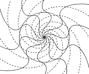
It is instructive to plot the geometries of the magnetic field and the current density for different values of  $\textit {Rm}$. For that we use the expressions derived in ((4.12) and (4.13)) and (F2) for the magnetic field, and ((E10)–(E15)) for the electrical current density. The geometries of the horizontal magnetic field lines and electric current lines are plotted in figure 6. The three components of the magnetic field normalized by
 $B_H(r=1)$ where
 $B_H$ is the modulus of the horizontal component
 $B_H=\sqrt {B_r^{2}+B_{\theta }^{2}}$, are given in figure 7. The three components of the current density, normalized by
 $\textit {Rm} B_H(r=1)$, are given in figure 8.
Plots of the magnetic field lines (full) and the electric current lines (dashed) in the horizontal plane  $(x,y)$, for
 $\mu =0$,
 $\sigma =10^{6}$,
 $\alpha =0.16 {\rm \pi}$ and different values of
 $\textit {Rm}$.

From left to right, plots of  $B_r$,
 $B_{\theta }$ and
 $-\mathrm {i} B_z$, normalized by
 $B_H(r=1)$, vs
 $\textit {Rm}(r-1)$, for
 $\mu =0$,
 $\sigma =10^{6}$,
 $\alpha =0.16 {\rm \pi}$ and
 $\textit {Rm} \in \{ 14.7,20,30,60,100,200,300\}$.

From left to right, plots of  $-\mathrm {i} J_r$,
 $-\mathrm {i} J_{\theta }$ and
 $J_z$, normalized by
 $\textit {Rm} B_H(r=1)$, vs
 $\textit {Rm}(r-1)$, for
 $\mu =0$,
 $\sigma =10^{6}$,
 $\alpha =0.16 {\rm \pi}$ and
 $\textit {Rm} \in \{ 14.7,20,30,60,100,200,300\}$.

In figure 6, we note that the geometry of the electric current lines in the  $(x,y)$-plane do not depend on
 $\textit {Rm}$. This is due to the fact that
 $\sigma \gg 1$. Indeed, from the expressions of
 $J_r$ and
 $J_{\theta }$ given in Appendix E ((E10)–(E14)) it can be shown that, for
 $\sigma \gg 1$ and provided that
 $\tilde {\gamma }/k^{2}$ is bounded, we have
 $J_{\theta }=-({c}/{s})J_r$ for both
 $r<1$ and
 $r>1$. This corresponds to having
 ${{\boldsymbol {J}}} \boldsymbol {\cdot } {{\boldsymbol {q}}} = 0$ or, equivalently, the electric current lines perpendicular to
 ${{\boldsymbol {q}}}$. In contrast, the geometry of the horizontal magnetic fields lines vary with
 $\textit {Rm}$, in such a way that a magnetic boundary layer seems to appear at
 $r=1$ for
 $\textit {Rm} \gg 1$. To quantify such a boundary layer, in figures 7 and 8 the components of
 ${{\boldsymbol {B}}}$ and
 ${{\boldsymbol {J}}}$ are plotted vs
 $\textit {Rm}(r-1)$, and it is obvious that the curves merge as
 $\textit {Rm}$ increases, suggesting that the thickness of the boundary layer is of the order of
 $O(\textit {Rm}^{-1})$.
5. Conclusions
We have shown that the anisotropic dynamo in cylindrical geometry is fast if the differential rotation is smooth, and furious if the shear is infinite. In both cases, the underlying mechanism is based on the stretching by differential rotation and anisotropic diffusion. For a smooth velocity profile, the dynamo occurs on a time scale equal to the turnover time  $t_{{Fast}}=|\varOmega (a)|^{-1}$, where
 $a$ is some characteristic radius, indicating for example the one at which the shear is maximum. If the shear is infinite at
 $r=a$, the dynamo occurs on a time scale
 $t_{{Furious}}$ even shorter that
 $|\varOmega (a)|^{-1}$. In dimensional units, it is equal to
 \begin{equation} t_{{Furious}}= (\textit{Rm} \varOmega (a))^{{-}1}=(\sigma_{{\perp}}\mu_{{\perp}}a^{2}\varOmega(a)^{2})^{{-}1}.\end{equation}
For  $\textit {Rm}\gg 1$ we then have
 $t_{{Furious}} \ll t_{{Fast}}$. This new characteristic time
 $t_{{Furious}}$ arises because, in the anisotropic dynamo, the mechanism of magnetic generation due to the anisotropic diffusion is particularly efficient, at least more efficient than the mechanism due to the isotropic diffusion on which, for example, the Ponomarenko dynamo partially works. As a result, the magnetic boundary layer in which the generation of the magnetic field occurs is thinner, leading to a magnetic growth faster than the fast Ponomarenko dynamo. To illustrate this, it is instructive to rewrite the system of (2.10a,b) in the following schematical way:
 \begin{gather} \gamma B_r \sim{-} k^{2} \textit{Rm}^{{-}1} B_r + k^{2} \textit{Rm}^{{-}1} B_{\theta} , \end{gather}
 \begin{gather}\gamma B_{\theta} \sim{-} k^{2} \textit{Rm}^{{-}1} B_{\theta} + k^{2} \textit{Rm}^{{-}1} B_r + r \varOmega'(r) B_r , \end{gather}
in which each term is a simplified expression of the original terms of (2.10a,b). On the right-hand side of (5.2a,b), the first term of each equation corresponds to the magnetic dissipation, acting against the dynamo action, the second terms are source terms for the dynamo due to the anisotropic diffusion while the third term of (5.2a) is also a source term, due to the velocity shear. Leaving aside temporarily the velocity term  $r\varOmega '(r) B_r$, all other terms of (5.2a,b) are of the same order of magnitude provided that
 \begin{equation} B_r\sim B_{\theta},\quad \text{and} \quad \gamma \sim k^{2} \textit{Rm}^{{-}1}. \end{equation}
The velocity term can be estimated as  $r\varOmega '(r) \sim 1$ if the shear is smooth and
 $r\varOmega '(r) \sim k$ if the shear is infinite. Assuming that in (5.2a,b) the velocity term is also of the same order of magnitude as the other terms, leads to
 $\gamma \sim 1$ and
 $k\sim Rm^{{1}/{2}}$ for the smooth shear, and to
 $\gamma \sim k\sim \textit {Rm}$ for the infinite shear. The thickness of the magnetic boundary layer that can be estimated as
 $\delta \sim k^{-1}$, then scales as
 $\delta \sim Rm^{-{1}/{2}}$ in the smooth case, and
 $\delta \sim Rm^{-1}$ in the infinite shear case. These orders of magnitude, confirmed by our previous findings, clearly establish the crucial role of the boundary layers.
In order to capture the difference from the Ponomarenko dynamo we can rewrite, again schematically, the system of equations given in Gilbert (Reference Gilbert1988, Reference Gilbert2003) as
 \begin{gather} \gamma B_r \sim{-} k^{2} \textit{Rm}^{{-}1} B_r + k \textit{Rm}^{{-}1} B_{\theta} , \end{gather}
 \begin{gather}\gamma B_{\theta} \sim{-} k^{2} \textit{Rm}^{{-}1} B_{\theta} + k \textit{Rm}^{{-}1} B_r + r \varOmega'(r) B_r . \end{gather}
In (5.4a),  $k \textit {Rm}^{-1} B_{\theta }$ is again a source term corresponding to the generation of
 $B_r$ from
 $B_{\theta }$, coming from the isotropic diffusion of
 $B_{\theta }$ in the
 $r$-direction. This term is to contrast with the anisotropic diffusion term
 $k^{2} \textit {Rm}^{-1} B_{\theta }$ in (5.2a). In both cases the diffusion is involved, but they have different orders of magnitude for
 $k\gg 1$. Assuming that the terms on the right-hand side of (5.4a) are of the same order of magnitude leads to
 \begin{equation} B_{\theta}\sim k B_r, \quad \text{and} \quad \gamma \sim k^{2} \textit{Rm}^{{-}1}. \end{equation}
Taking the same estimation of the velocity term  $r\varOmega '(r)$ as above,
 $r\varOmega '(r) \sim 1$ if the shear is smooth and
 $\varOmega '(r) \sim k$ if the shear is infinite, and assuming that it is of the same order of magnitude as the other terms of (5.4b), except the term
 $k \textit {Rm}^{-1} B_r$ which is smaller for
 $k\gg 1$, leads to
 $\gamma \sim k^{-1}\sim Rm^{-{1}/{3}}$ for the smooth shear, and to
 $\gamma \sim 1$ and
 $k\sim \textit {Rm}^{{1}/{2}}$ for the infinite shear. The thickness of the magnetic boundary layer,
 $\delta \sim k^{-1}$, then scales as
 $\delta \sim Rm^{-{1}/{3}}$ in the smooth case, and
 $\delta \sim Rm^{-{1}/{2}}$ in the infinite shear case.
Eventually, a unique characteristic time can be defined, as
 \begin{equation} t = \sigma_{{\perp}} \mu_{{\perp}} \delta^{2},\end{equation}
with, for the Ponomarenko dynamo,  $\sigma _{\perp }=\sigma _{\parallel }$ and
 $\mu _{\perp }=\mu _{\parallel }$. In (5.6),
 $t$ corresponds to the magnetic diffusion time through a magnetic boundary layer of thickness
 $\delta$. Replacing
 $\delta /a$ by either
 $Rm^{-{1}/{3}}$,
 $Rm^{-{1}/{2}}$ or
 $Rm^{-1}$ leads to a characteristic time equal to
 $Rm^{-{1}/{3}}\varOmega (a)^{-1}$,
 $\varOmega (a)^{-1}$ or
 $Rm^{-1}\varOmega (a)^{-1}$, as summarized in table 1. Therefore, as mentioned above, it is mainly the thickness of the boundary layer that governs the characteristic time of the dynamo action, and thus the ability to have a slow, fast or furious dynamo for increasingly thin boundary layers.
The  $\textit {Rm}$-power scalings of the thickness
 $\delta$ of the magnetic boundary layer, and of the characteristic time
 $t$ of the dynamo. These two quantities satisfy the unique formula (5.6).

Such an anisotropic dynamo can be designed at the laboratory scale, using appropriate conducting layers or coils, or high-permeability materials, in order to mimic the homogeneous anisotropy considered here. According to figure 5, to successfully demonstrate the furious aspect of such a dynamo, a minimum magnetic Reynolds number of approximately 30 would be necessary, which is approximately twice the value 14.6 of the dynamo threshold. From the estimate given in Plunian & Alboussière (Reference Plunian and Alboussière2020), assuming an electrical conductivity equal to that of copper would require an inner cylinder with a radius of 0.05 m and a rotation frequency of approximately 25 Hz, which is feasible in the laboratory. In natural objects where the magnetic Reynolds number is much larger, fast or furious dynamo action should be favoured, provided that the anisotropy of the electrical conductivity does play a role, as can be expected for example in spiral arm galaxies where  $\textit {Rm} \gg 1$ and for which our anisotropic model might be a good approximation.
Acknowledgements
We acknowledge A. Gilbert for his interest in our work and his helpful comments.
Declaration of interests
The authors report no conflict of interest.
Appendix A. Derivation of (2.10a,b)
The induction equation (2.5) is derived from (2.4d) and (2.4e), such that
 \begin{equation} \partial_t {{\boldsymbol{B}}}= \boldsymbol{\nabla} \times ({{\boldsymbol{U}}} \times {{\boldsymbol{B}}}) - \boldsymbol{\nabla} \times \lbrack\sigma_{ij}\rbrack^{{-}1}{{\boldsymbol{J}}}, \end{equation}
 \begin{equation} {{\boldsymbol{J}}}= \boldsymbol{\nabla} \times \lbrack\mu_{ij}\rbrack^{{-}1}{{\boldsymbol{B}}}. \end{equation}
Assuming axisymmetry ( $\partial _{\theta }=0$) and considering the solenoidality of
 ${{\boldsymbol {B}}}$ given by (2.4b), the curl of the cross-product of
 ${{\boldsymbol {U}}}=r\varOmega (r) {{\boldsymbol {e}}}_{\theta }$ by
 ${{\boldsymbol {B}}}=(B_r, B_{\theta }, B_z )\exp (\gamma t + \mathrm {i} k z)$ takes the form
 \begin{equation} \boldsymbol{\nabla} \times ({{\boldsymbol{U}}} \times {{\boldsymbol{B}}})=r\varOmega' B_r {{\boldsymbol{e}}}_{\theta}, \end{equation}
where, from now, the exponential term is dropped for convenience. From the definition (2.6a) of  $\lbrack \sigma _{ij}\rbrack ^{-1}$, we have
 \begin{equation} \lbrack\sigma_{ij}\rbrack^{{-}1} {{\boldsymbol{J}}}=\sigma_{{\perp}}^{{-}1}\begin{pmatrix} (1+\sigma c^{2})J_r+ \sigma cs J_{\theta}\\ \sigma cs J_r + (1+\sigma s^{2})J_{\theta}\\ J_z \end{pmatrix}.\end{equation}
Taking the curl leads to
 \begin{equation} \boldsymbol{\nabla} \times \lbrack\sigma_{ij}\rbrack^{{-}1} {{\boldsymbol{J}}} = \sigma_{{\perp}}^{{-}1}\begin{pmatrix} -\mathrm{i} k[\sigma cs J_r + (1+\sigma s^{2})J_{\theta}] \\ \mathrm{i} k^{{-}1}[D_k(J_r)+\sigma c^{2} k^{2} J_r+ \sigma cs k^{2} J_{\theta}] \\ \frac{1}{r}\partial_r(r[\sigma csJ_r+(1+\sigma s^{2})J_{\theta}]) \end{pmatrix}, \end{equation}
where, again,  $D_{\nu }(X)=\nu ^{2}X-\partial _r(({1}/{r})\partial _r(rX))$, and with
 $J_z=\mathrm {i} k^{-1}({1}/{r})\partial _r(rJ_r)$ coming from the solenoidality of the current density.
Similarly, we find that
 \begin{equation} {{\boldsymbol{J}}}=\boldsymbol{\nabla} \times \lbrack\mu_{ij}\rbrack^{{-}1}{{\boldsymbol{B}}}= \mu_{{\perp}}^{{-}1}\begin{pmatrix} -\mathrm{i} k[ \mu cs B_r + (1+\mu s^{2})B_{\theta}] \\ \mathrm{i} k^{{-}1}[D_k(B_r)+\mu c^{2}k^{2} B_r+\mu csk^{2} B_{\theta}] \\ \frac{1}{r}\partial_r(r[\mu csB_r +(1+\mu s^{2})B_{\theta}]) \end{pmatrix}. \end{equation}
Combining (A5) and (A6) leads to
 \begin{equation} \boldsymbol{\nabla} \times \lbrack\sigma_{ij}\rbrack^{{-}1} [\boldsymbol{\nabla} \times \lbrack\mu_{ij}\rbrack^{{-}1}{{\boldsymbol{B}}}]= (\sigma_{{\perp}}\mu_{{\perp}})^{{-}1}\begin{pmatrix} F \\ G \\ \mathrm{i} k^{{-}1}\left(\dfrac{1}{r}\partial_r(rF)\right) \end{pmatrix}, \end{equation}
with
 \begin{gather} F= \mu c^{2} k^{2} B_r +(1+\sigma s^{2}) D_k(B_r) - k^{2} cs (\sigma -\mu)B_{\theta}, \end{gather}
 \begin{gather}G={-} cs (\sigma -\mu) D_k(B_r) + \sigma k^{2} c^{2} B_{\theta} + (1+\mu s^{2}) D_k(B_{\theta}). \end{gather}
Appendix B. Derivation of (4.10a,b)
Rewriting (4.1a,b) in the form
 \begin{gather} D_k(B_r) ={-}[\tilde{\gamma} B_r + \mu c^{2}k^{2} B_r + \sigma s^{2} D_k(B_r) - cs(\sigma -\mu)k^{2} B_{\theta} ] , \end{gather}
 \begin{gather}D_k (B_{\theta}) ={-} [ \tilde{\gamma} B_{\theta} + \sigma c^{2}k^{2} B_{\theta} + \mu s^{2}D_k (B_{\theta}) - cs(\sigma -\mu) D_k(B_r) ], \end{gather}
and considering the linear combination  $c$(B1a)+
 $s$(B1b), leads to
 \begin{equation} (1+\mu s^{2}) D_k(c B_r + s B_{\theta})={-} (\tilde{\gamma}+\mu c^{2} k^{2}) (c B_r + s B_{\theta}). \end{equation}
Then, using the identity
 \begin{equation} (1+\mu s^{2}) D_k(X)=(1+\mu s^{2})D_{k_{\mu}}(X) - (\tilde{\gamma}+\mu c^{2} k^{2}) X, \end{equation}
we find that
 \begin{equation} D_{k_{\mu}}(c B_r + s B_{\theta})=0. \end{equation}
In a similar way, considering the linear combination  $s D_k$((B1a))-
 $ck^{2}$(B1b), leads to
 \begin{equation} (1+\sigma s^{2}) D_k(s D_k(B_r) -ck^{2} B_{\theta})={-} (\tilde{\gamma}+\sigma c^{2} k^{2}) (s D_k(B_r) -ck^{2} B_{\theta}). \end{equation}
Then, using the identity
 \begin{equation} (1+\sigma s^{2}) D_k(X)=(1+\sigma s^{2})D_{k_{\sigma}}(X) - (\tilde{\gamma}+\sigma c^{2} k^{2}) X, \end{equation}
we find that
 \begin{equation} D_{k_{\sigma}}(s D_k(B_r) -ck^{2} B_{\theta})=0. \end{equation}
Appendix C. Derivation of (4.13)
To obtain  $B_{\theta }$ from
 $B_r$ by replacing (4.12) in (4.9a), we need to calculate
 $D_{k_{\sigma }}(B_r)$, given by
 \begin{equation} D_{k_{\sigma}}(B_r)= \left\{ \begin{array}{@{}ll} r< 1, & -s \lambda_{\mu} \dfrac{D_{k_{\sigma}}(I_1(k_{\mu} r))}{I_1(k_{\mu})} \\ r> 1, & -s \lambda_{\mu} \dfrac{D_{k_{\sigma}}(K_1(k_{\mu} r))}{K_1(k_{\mu})} \end{array} \right. . \end{equation}
With the help of the identity (4.8) we have
 \begin{equation} D_{k_{\sigma}}(B_r)= \left\{ \begin{array}{@{}ll} r< 1, & -s \lambda_{\mu} (k_{\sigma}^{2}-k_{\mu}^{2})\dfrac{I_1(k_{\mu} r)}{I_1(k_{\mu})} \\ r> 1, & -s \lambda_{\mu} (k_{\sigma}^{2}-k_{\mu}^{2})\dfrac{K_1(k_{\mu} r)}{K_1(k_{\mu})} \end{array} \right. . \end{equation}
Replacing  $k_{\sigma }$ and
 $k_{\mu }$ by their expressions given in (4.7a,b) and after some additional algebra this leads to (4.13).
Appendix D. Derivation of the boundary condition (4.14)
To write the continuity of  $\partial _r B_r$ at
 $r=1$ we first need to calculate the expression of
 $\partial _r B_r$ at any
 $r$. From the following identities satisfied for any
 $\nu$
 \begin{gather} \partial_r (I_1(\nu r))= \nu I_0(\nu r) -\frac{1}{r}I_1(\nu r), \end{gather}
 \begin{gather}\partial_r (K_1(\nu r))={-}\nu K_0(\nu r) -\frac{1}{r}K_1(\nu r), \end{gather}
the expression of  $\partial _r B_r$ is obtained by deriving (4.12)
 \begin{equation} \partial_r B_r= \left\{ \begin{array}{@{}ll} r\le 1, & -s \dfrac{\lambda_{\sigma}}{I_1(k_{\sigma})} [k_{\sigma} I_0(k_{\sigma} r) -\dfrac{1}{r}I_1(k_{\sigma} r)] \\ & -s \dfrac{\lambda_{\mu}}{I_1(k_{\mu})} [k_{\mu} I_0(k_{\mu} r) -\dfrac{1}{r}I_1(k_{\mu} r)] \\ r\ge 1, & s \dfrac{\lambda_{\sigma}}{K_1(k_{\sigma})} [ k_{\sigma} K_0(k_{\sigma} r) +\dfrac{1}{r}K_1(k_{\sigma} r) ]\\ & s\dfrac{\lambda_{\mu}}{K_1(k_{\mu})} [ k_{\mu} K_0(k_{\mu} r) +\dfrac{1}{r}K_1(k_{\mu} r) ] \end{array} \right. .\end{equation}
Then, from (D3) writing the continuity of  $\partial _r B_r$ at
 $r=1$ leads to (4.14).
Appendix E. Derivation of the current density ${{J}}$

The current density  ${{\boldsymbol {J}}}$ given in (A6) can be written, in its renormalized form, as
 \begin{equation} {{\boldsymbol{J}}}= \begin{pmatrix} -\mathrm{i} k \phi \\ \mathrm{i} k^{{-}1}[D_k(B_r)+\mu c^{2}k^{2} B_r+\mu csk^{2} B_{\theta}] \\ \frac{1}{r}\partial_r(r\phi) \end{pmatrix}, \end{equation}
with  $\phi =\mu cs B_r + (1+\mu s^{2})B_{\theta }$.
Replacing  $B_r$ and
 $B_{\theta }$ by their expressions (4.12) and (4.13), leads to
 \begin{equation} \phi= \left\{ \begin{array}{@{}ll} r< 1, & c \left[\lambda_{\sigma}\dfrac{I_1(k_{\sigma}r)}{I_1(k_{\sigma})} + \dfrac{s^{2} \tilde{\gamma}}{c^{2}k^{2}}\lambda_{\mu}\dfrac{I_1(k_{\mu}r)}{I_1(k_{\mu})}\right]\\ r> 1, & c \left[\lambda_{\sigma}\dfrac{K_1(k_{\sigma}r)}{K_1(k_{\sigma})} + \dfrac{s^{2} \tilde{\gamma}}{c^{2}k^{2}}\lambda_{\mu}\dfrac{K_1(k_{\mu}r)}{K_1(k_{\mu})}\right] \end{array} \right., \end{equation}
and therefore to  $J_r$.
Using the relations (D1) and (D2) written in the form
 \begin{gather} \frac{1}{r}\partial_r (rI_1(\nu r))= \nu I_0(\nu r) , \end{gather}
 \begin{gather}\frac{1}{r}\partial_r (rK_1(\nu r))={-}\nu K_0(\nu r) , \end{gather}
leads to
 \begin{equation} \frac{1}{r}\partial_r(r\phi )= \left\{ \begin{array}{@{}ll} r< 1, & c\left[\lambda_{\sigma}k_{\sigma} \dfrac{I_0(k_{\sigma}r)}{I_1(k_{\sigma})} + \dfrac{s^{2} \tilde{\gamma}}{c^{2}k^{2}}\lambda_{\mu}k_{\mu} \dfrac{I_0(k_{\mu}r)}{I_1(k_{\mu})} \right] \\ r> 1, & -c\left[\lambda_{\sigma}k_{\sigma} \dfrac{K_0(k_{\sigma}r)}{K_1(k_{\sigma})} + \dfrac{s^{2} \tilde{\gamma}}{c^{2}k^{2}}\lambda_{\mu}k_{\mu} \dfrac{K_0(k_{\mu}r)}{K_1(k_{\mu})} \right] \end{array} \right. , \end{equation}
and therefore to  $J_z$.
Using (B3), we find that
 \begin{equation} D_k(B_r)+\mu c^{2} k^{2}B_r+\mu cs k^{2} B_{\theta} = D_{k_{\mu}}(B_r)+\frac{\mu csk^{2}\phi-\tilde{\gamma}B_r}{1+\mu s^{2}}. \end{equation}
From the expression of  $B_r$ given by (4.12), we have
 \begin{equation} D_{k_{\mu}}(B_r)= \left\{ \begin{array}{@{}ll} r< 1, & -\dfrac{s\lambda_{\sigma}}{I_1(k_{\sigma})} D_{k_{\mu}}(I_1(k_{\sigma} r)) \\ r> 1, & -\dfrac{s\lambda_{\sigma}}{K_1(k_{\sigma})} D_{k_{\mu}}(K_1(k_{\sigma} r)) \end{array} \right. . \end{equation}
Using (4.8) leads to
 \begin{equation} D_{k_{\mu}}(B_r)= \left\{ \begin{array}{@{}ll} r< 1, & -\dfrac{s\lambda_{\sigma}}{I_1(k_{\sigma})} (k_{\mu}^{2}-k_{\sigma}^{2})I_1(k_{\sigma} r) \\ r> 1, & -\dfrac{s\lambda_{\sigma}}{K_1(k_{\sigma})} (k_{\mu}^{2}-k_{\sigma}^{2})K_1(k_{\sigma} r) \end{array} \right. , \end{equation}
where we used the identity  $D_{\nu }(I_1(k_{\nu } r))=D_{\nu }(K_1(k_{\nu } r))=0$. After some algebra we find that
 \begin{equation} D_{k_{\mu}}(B_r)\!+\!\frac{\mu csk^{2}\phi\!-\!\tilde{\gamma}B_r}{1\!+\!\mu s^{2}}= \left\{ \begin{array}{@{}ll} r< 1, & \lambda_{\sigma}sk^{2} \left(\dfrac{\sigma c^{2}+\tilde{\gamma}/k^{2}}{1+\sigma s^{2}}\right)\dfrac{I_1(k_{\sigma}r)}{I_1(k_{\sigma})} +s\tilde{\gamma}\lambda_{\mu}\dfrac{I_1(k_{\mu}r)}{I_1(k_{\mu})}\\ r\!>\! 1, & \lambda_{\sigma}sk^{2} \left(\dfrac{\sigma c^{2}\!+\!\tilde{\gamma}/k^{2}}{1\!+\!\sigma s^{2}}\right)\dfrac{K_1(k_{\sigma}r)}{K_1(k_{\sigma})} \!+\!s\tilde{\gamma}\lambda_{\mu}\dfrac{K_1(k_{\mu}r)}{K_1(k_{\mu})} \end{array} \right., \end{equation}
leading to  $J_{\theta }$.
Then the current density takes the following form for  $r<1$:
 \begin{gather} J_r={-}\mathrm{i} k c \left[\lambda_{\sigma}\frac{I_1(k_{\sigma}r)}{I_1(k_{\sigma})} + \frac{s^{2} \tilde{\gamma}}{c^{2}k^{2}}\lambda_{\mu}\frac{I_1(k_{\mu}r)}{I_1(k_{\mu})}\right], \end{gather}
 \begin{gather}J_{\theta}= \mathrm{i} k^{{-}1} \left[\lambda_{\sigma}sk^{2} \left(\frac{\sigma c^{2}+\tilde{\gamma}/k^{2}}{1+\sigma s^{2}}\right)\frac{I_1(k_{\sigma}r)}{I_1(k_{\sigma})}+s\tilde{\gamma}\lambda_{\mu}\frac{I_1(k_{\mu}r)}{I_1(k_{\mu})}\right], \end{gather}
 \begin{gather}J_z= c\left[\lambda_{\sigma}k_{\sigma}\frac{I_0(k_{\sigma}r)}{I_1(k_{\sigma})} + \frac{s^{2} \tilde{\gamma}}{c^{2}k^{2}}\lambda_{\mu}k_{\mu}\frac{I_0(k_{\mu}r)}{I_1(k_{\mu})} \right], \end{gather}
for  $r>1$,
 \begin{gather} J_r={-}\mathrm{i} k c \left[\lambda_{\sigma}\frac{K_1(k_{\sigma}r)}{K_1(k_{\sigma})} + \frac{s^{2} \tilde{\gamma}}{c^{2}k^{2}}\lambda_{\mu}\frac{K_1(k_{\mu}r)}{K_1(k_{\mu})}\right], \end{gather}
 \begin{gather}J_{\theta}= \mathrm{i} k^{{-}1} \left[\lambda_{\sigma}sk^{2} \left(\frac{\sigma c^{2}+\tilde{\gamma}/k^{2}}{1+\sigma s^{2}}\right)\frac{K_1(k_{\sigma}r)}{K_1(k_{\sigma})}+s\tilde{\gamma}\lambda_{\mu}\frac{K_1(k_{\mu}r)}{K_1(k_{\mu})}\right], \end{gather}
 \begin{gather}J_z={-}c\left[\lambda_{\sigma}k_{\sigma}\frac{K_0(k_{\sigma}r)}{K_1(k_{\sigma})} + \frac{s^{2} \tilde{\gamma}}{c^{2}k^{2}}\lambda_{\mu}k_{\mu}\frac{K_0(k_{\mu}r)}{K_1(k_{\mu})} \right]. \end{gather}
Appendix F. Derivation of $Bz$

From (3.6) we have
 \begin{equation} B_z = \mathrm{i} k^{{-}1} \left(\frac{B_r}{r}+\partial_rB_r\right).\end{equation}
Then replacing (4.12) and (D3) in (F1), leads to
 \begin{equation} B_z= \mathrm{i} k^{{-}1} s \left\{ \begin{array}{@{}ll} r< 1, & -\left[\lambda_{\sigma}k_{\sigma}\dfrac{I_0(k_{\sigma}r)}{I_1(k_{\sigma})} + \lambda_{\mu}k_{\mu}\dfrac{I_0(k_{\mu}r)}{I_1(k_{\mu})} \right] \\ r>1, & \lambda_{\sigma}k_{\sigma}\dfrac{K_0(k_{\sigma}r)}{K_1(k_{\sigma})} + \lambda_{\mu}k_{\mu}\dfrac{K_0(k_{\mu}r)}{K_1(k_{\mu})} \end{array} \right. .\end{equation}



