I. INTRODUCTION
It is well known that aniline and its derivates are one of the most important chemicals and intermediates in the chemical industry for the production of polymers, pharmaceuticals, herbicides, and dyes, Reference Downing, Kunkeler and Bekkum1–Reference Meng, Cheng, Akiyama, Hao, Qiao, Yu, Zhao, Fujita and Arai4 so the heterogeneous hydrogenation of substituted nitrobenzene has attracted more attention. Nowadays, AN (aniline) is produced generally via hydrogenation of nitrobenzene (NB) over Raney Ni catalyst, noble metals (Pt, Pd), Reference Holler, Wegricht, Yuranov, Minsker and Renken5,Reference Corma, Serna, Concepcion and Calvino6 transition metals (Cu, Ni), Reference Diao, Qian, Luo, Wei and Wang7 and metal-free catalysts (C60). Reference Li and Xu8 NB hydrogenation proceeds easily on noble metal catalysts Reference Macías Pérez, Salinas Martínez de Lecea and Linares Solano9 which are limited due to the high cost and scarce resources. Ni–B amorphous alloys and Ni nanoparticles supported on the silica have been applied widely due to higher activity and lower price, Reference Burge, Collins and Davis10–Reference Wang, Yuan, Nie, Hou and Zheng17 however this reaction must be carried out at higher temperature, higher H2 pressure, with longer time to reach a satisfied selectivity of AN. Reference Li, Zhao, Wan, Dai and Qiao11,Reference Lee and Chen12
Recently, bimetallic catalysts with the addition of the second metal for providing a method of controlling the activity, selectivity, and stability of the catalysts in certain reactions have received more and more attention. Reference Toshima and Yonezawa18 The preparation method of metals supported on the silica catalysts may also have an important effect on its catalytic activity. The frequently-used methods for metal incorporation supported on the silica are the incipient wetness impregnation, whether monometal Reference Relvas, Andrade, Freire, Lemos, Araujo, Pinho, Nunes and Ribeiro16,Reference Wang, Yuan, Nie, Hou and Zheng17 or bimetallic. Reference Carrero, Calles and Vizcaíno19–Reference Fang, Yao, Qing and Li24 The morphology and surface area of materials have an important effect on the catalytic activity, which may change the active sites. In addition, the smaller particles can achieve high dispersion of the active phase. Hollow spheres with high monodispersion have possessed the higher surface area and controllable morphology. The synthesis of the monodispersed hollow spheres often relies on templating approaches, in which hard or soft sacrificial template method was used to establish the hollow structure. Reference Wang, Yang, Tang, Dong, Jin, Yang, Kisailus, Zhao, Tang and Wang25 However, the traditional physical template synthesis has some shortcomings. For example, the core could not directly participate in the formation of the shell wall and has to be removed at the end of the reaction, which makes the whole process more complicated. Herein, an effective hydrothermal route based on a sacrificial templating process has been developed to prepare mesoporous hollow microstructures of various silicate materials as well as the corresponding yolk–shell structures (some necessary parameters involved are also discussed). In comparison with the traditional synthesis of monodispersed spheres, the sacrificial template approach can avoid subsequent troublesome procedures for the removal of templates. For exploring a controllable synthetic method, our group has successfully developed a one-step sacrificial self-template/interface approach to get mesoporous SiO2/Ni3Si2O5(OH)4 core–shell microspheres with tunable chamber structures, Reference Guo, Du, Li and Cui26 and studied the catalytic properties of mesoporous nickel/silica core–shell microspheres, which are the reduced product of the mesoporous SiO2/Ni3Si2O5(OH)4 core–shell microspheres under hydrogen atmosphere. Reference Chen, Guo, Sun and Du27 However, the synthesis of bimetallic catalyst Ni–Fe/SiO2 and its catalytic activity on hydrogenation of nitrobenzene have not been studied before. In this work, the characteristics and the catalytic behavior of bimetallic catalyst Ni–Fe/SiO2 obtained by one-step self-template synthesis are compared to monometal catalyst Fe/SiO2 prepared by the same method. A series of evidences of the formation of bimetallic (Ni,Fe2+)3Si2O5(OH)4 are received to explain the formation of hollow microspheres. By altering reaction conditions such as reaction time or adjusting reaction temperature, the difference of changes on morphology of (Ni,Fe2+)3Si2O5(OH)4 appeared. Bimetallic catalysts Ni–Fe/SiO2 were reduced in situ under the hydrogen atmosphere and the catalytic activities were evaluated by the nitrobenzene hydrogenation reaction at 373 K and 3.0 MPa. Reference Rong, Long, Zhang, Huang and Yu28,Reference Alvarez-Ramírez, Toledo-Antonio, Angeles-Chavez, Guerrero-Abreo and Lopez-Salinas29
II. EXPERIMENTAL
A. Material and methods
Nitrobenzene was purchased from Jiangsu Qiangsheng Function Chemical Reagent Co. (Jiangsu, China). Tetraethoxysilane (TEOS) was purchased from Tianjin Bodi Chemical Reagent Co. (Tianjin, China). All other reagents were of analytic grade without further purification. The X-ray powder diffraction (XRD) patterns were obtained on an X-ray diffractometer (D/MAX-500, Rigaku Corporation, Tokyo, Japan, λ = 0.15418 nm at 40 kV and 70 mA; Philips X’pert diffractometer, PANalytical, Westborough, Massachusetts) equipped with Cu Kα radiation over the 2θ range from 10° to 80°. The composition of the samples was determined by energy-dispersive X-ray spectrum (EDS) which is the attachment of the scanning electron microscope (SEM; JSM 6700F, JEOL Ltd., Tokyo, Japan). The morphology of the as-prepared samples was studied by the field emission scanning electron microscopy (FESEM; JSM 6700F, JEOL Ltd.) and the transmission electron microscope (TEM; H-7650, Hitachi Corp., Tokyo, Japan). The specific surface area was received by the Brunauer–Emmett–Teller (BET) method and the pore size distribution was counted from the adsorption branch using the Barrett–Joyner–Halenda (BJH) theory by using a porosimetry analyzer (Micromeritics ASAP 2020, Norcross, Georgia). The reduction behavior was examined by temperature-programmed reduction (TPR) on a ChemiSorb 2750 instrument (Micromeritics) fed with a 10% H2/Ar mixture. The concentration of Ni, Fe, and Si ions was measured using inductively coupled plasma-atomic emission spectroscopy (ICP; Atomscan Advantage, Thermo Jarrell Ash, Franklin, Massachusetts).
B. Synthesis of the Ni–Fe/SiO2 microspheres
Monodispersed silica spheres as the template were prepared according to the famous Stöber method Reference Stöber and Fink30 with some changes. SiO2 (0.8 mmol) was dispersed into 50 mL distilled water ultrasonically for 30 min to form uniform solution, and then NiSO4·6H2O (0.3 mmol), NaCH3COO (6 mmol), and FeSO4·7H2O (0.6 mmol) were dissolved into mixed solutions under magnetic stirring for 30 min. Then, the solution was transferred into a Teflon-line stainless steel autoclave and treated hydrothermally at 140 °C for 24 h. Subsequently the temperature was raised to 180 °C and maintained for 12 h. The obtained precipitates were collected by centrifugation and washed with distilled water to remove ions possibly remaining in the final products till neutral, and finally dried at 80 °C.
Bimetallic (Ni,Fe2+)3Si2O5(OH)4 hollow spheres were reduced by using in situ under the hydrogen atmosphere at 650 °C according to the temperature-programmed reduction (TPR) for 5 h, bimetallic catalyst Ni–Fe/SiO2 hollow spheres were obtained.
C. Catalytic activity of bimetallic catalyst Ni–Fe/SiO2 microspheres
The catalytic activity of bimetallic catalyst Ni–Fe/SiO2 microspheres was evaluated by catalyzing the liquid phase hydrogenation of nitrobenzene at 373 K and 3.0 MPa. The experiment was carried out in a 1000 mL stainless steel autoclave reactor. Nitrobenzene (6 mL) and the catalyst (0.6 g) dispersed in ethanol (300 mL, as solvent) were added into the high pressure reactor. There were some steps before the hydrogenation. Firstly, air was flushed out of the reactor through vacuum pump at room temperature and H2 was then filled into the reactor. After repeating the above step one more time, the reactor was charged with H2 to 3.0 MPa and heated to 373 k, and the reaction was started with stirring at 500 rpm. During the reaction, a series of samples were withdrawn periodically and analyzed.
III. RESULTS AND DISCUSSION
A. Synthesis of bimetallic (Ni,Fe2+)3Si2O5(OH)4 hollow microspheres
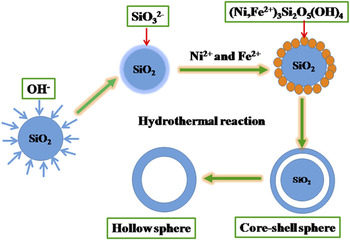
Bimetallic (Ni,Fe2+)3Si2O5(OH)4 hollow microspheres with tunable chamber structures and controllable morphology have been obtained. Figure 1 schematically illustrated the synthesis process. In the process of preparation of (Ni,Fe2+)3Si2O5(OH)4 hollow microspheres, silica spheres played both as template and the source of silicon. Silica spheres were dispersed into an alkaline solution containing NiSO4·6H2O, NaCH3COO, and FeSO4·7H2O. Silica spheres were dissolved and subsequently silicate anion was formed as the surface active sites, Reference Palmer and Drummond31,Reference Iler32 which would easily react with metal ions and the products were deposited upon the surface of silica spheres. When the amount of silicate ions around silica spheres was higher than that in the other site of the autoclave and the active positions existed on the surface of silica spheres, the generated bimetallic (Ni,Fe2+)3Si2O5(OH)4 were easier to deposit on the surface of silica spheres. During this process, Ni2+ and Fe2+ continuously took parts in the building the shell of (Ni,Fe2+)3Si2O5(OH)4 microspheres. Finally, bimetallic (Ni, Fe2+)3Si2O5(OH)4 hollow microspheres were formed.
Schematic illustration of the preparation of (Ni,Fe2+)3Si2O5(OH)4 hollow microspheres.

B. Morphology of (Ni,Fe2+)3Si2O5(OH)4 and Ni–Fe/SiO2 microspheres
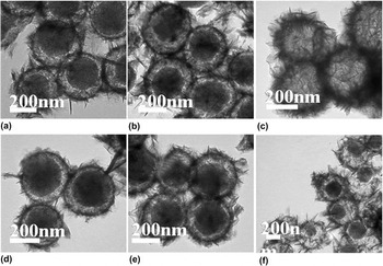
The growth process of hierarchical hollow microspheres was investigated by time and temperature depended experiments, and the morphology of the products was examined by the field emission scanning electron microscopy (SEM) and transmitting electron microscopy (TEM). As shown in Fig. 2(a), the clearly blank boundary appearing indicated the formation of a core–shell structure, and a complete thin shell with an obvious rough surface was observed upon the surface of silica spheres. When the reaction was prolonged, obvious voids appeared, indicating that (Ni,Fe2+)3Si2O5(OH)4 hollow microspheres were formed [Fig. 2(c)], and the thickness of the shell was found to be uniform and thicker than that of the products shown in Figs. 2(a) and 2(b). Bimetallic (Ni,Fe2+)3Si2O5(OH)4 hollow microspheres were prepared using continuous heating with different temperature. As shown in Figs. 2(d)–2(f), the uniform hollow microspheres were not obtained under 140 °C or 180 °C solely, even though the reaction time was prolonged for 36 h. In other words, bimetallic (Ni,Fe2+)3Si2O5(OH)4 hollow microspheres could not be obtained using the sole temperature.
TEM micrographs of the products prepared using different reaction conditions: the molar ratio of Ni/Fe = 1:2, (a) 140 °C–24 h + 180 °C–3 h, (b) 140 °C–24 h + 180 °C–6 h, (c) 140 °C–24 h + 180 °C–12 h, (d) 140 °C–12 h, (e) 140 °C–36 h, (f) 180 °C–12 h.

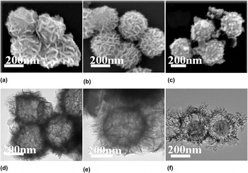
The SEM images of (Ni,Fe2+)3Si2O5(OH)4, Ni3Si2O5(OH)4, and Fe2+ 3(Si2O5)2(OH)2 microspheres [Figs. 3(a)–3(c)] showed that the morphology of (Ni,Fe2+)3Si2O5(OH)4 microspheres was similar with that of the monometallic silicate Ni3Si2O5(OH)4, but different from Fe2+ 3(Si2O5)2(OH)2 microspheres. To show the more details of the difference between their surface morphology, representative TEM images of (Ni,Fe2+)3Si2O5(OH)4 hollow spheres, Ni3Si2O5(OH)4 hollow spheres and Fe2+ 3(Si2O5)2(OH)2 core–shell spheres were presented in Figs. 3(d)–3(f). As shown in Figs. 3(d)–3(f), the sheet-like hollow spheres of (Ni,Fe2+)3Si2O5(OH)4 were slightly dense compared with Ni3Si2O5(OH)4 hollow spheres, but rode-like core–shell spheres of Fe2+ 3(Si2O5)2(OH)2 [Fig. 3(f)] were obviously different from sheet-like hollow spheres of (Ni,Fe2+)3Si2O5(OH)4 [Fig. 3(d)] and Ni3Si2O5(OH)4 [Fig. 3(e)]. It is necessary to point out that Fe2+ 3(Si2O5)2(OH)2 was core–shell spheres structure while (Ni,Fe2+)3Si2O5(OH)4 was hollow spheres structure under the same reaction conditions, which indicated that nickel ion could accelerate the reaction for the synergistic effect.
SEM micrographs of (a) (Ni,Fe2+)3Si2O5(OH)4 hollow spheres (b) Ni3Si2O5(OH)4 hollow spheres (c) (Fe2+)3(Si2O5)2(OH)2 core–shell microspheres; TEM micrographs of (d) (Ni,Fe2+)3Si2O5(OH)4 hollow spheres (e) Ni3Si2O5(OH)4 hollow sphere (f) (Fe2+)3(Si2O5)2(OH)2 core–shell microspheres. The reaction conditions: (a) 140 °C–24 h + 180 °C–12 h (b) 180 °C–24 h, (c) 140 °C–24 h + 180 °C–12 h.

Energy-dispersive X-ray spectroscopy (EDX) line scanning and elemental mapping were used to confirm the detailed information about the structure and local atomic composition. In Figs. S1 and S2, elemental mapping images of Fe and Ni reveal that Fe and Ni were uniformly distributed at the periphery of the sample spheres, further demonstrating Ni and Fe existing on the shell of spheres. The contents of Fe and Ni obtained from the EDX spectrum (Fig. S3) were 26 and 8%, and the contents of Fe and Ni in Fig. S4 were 32 and 17%.
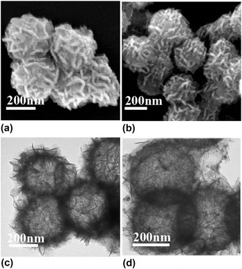
As shown in Fig. 4, Ni–Fe/SiO2 hollow microspheres have similar surface morphology with (Ni,Fe2+)3Si2O5(OH)4 hollow spheres, which indicated nickel and iron ions were reduced in situ and the structures were maintained after reduction. However, it should be noted that the detailed surface morphology was different. The nanosheets which existed part of nanoparticles were less than that before reduction.
SEM micrographs of (Ni,Fe2+)3Si2O5(OH)4 hollow microspheres (a, unreduced) and Ni–Fe/SiO2 hollow microspheres (b, reduced), TEM micrographs of (Ni,Fe2+)3Si2O5(OH)4 hollow microspheres (c, unreduced) and Ni–Fe/SiO2 hollow microspheres (d, reduced).

C. Structure of (Ni,Fe2+)3Si2O5(OH)4 and Ni–Fe/SiO2 microspheres
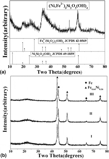
The X-ray powder diffraction (XRD) analysis was performed on an X-ray diffractometer (Philips X’pert diffractometer with Cu Kα radiation). The powder X-ray diffraction (XRD) pattern of bimetallic (Ni,Fe2+)3Si2O5(OH)4 hollow spheres was shown in Fig. 5(a), which was in agreement with previous reports. Reference Alvarez-Ramírez, Toledo-Antonio, Angeles-Chavez, Guerrero-Abreo and Lopez-Salinas29,Reference Palmer and Drummond31 Standard XRD patterns of Fe2+ 3(Si2O5)2(OH)2 (JCPDS 42–0569) and Ni3Si2O5(OH)4 (JCPDS 49–1859) were also shown for comparison. The diffraction peaks of Fe2+ 3(Si2O5)2(OH)2 and Ni3Si2O5(OH)4 in XRD pattern of bimetallic (Ni,Fe2+)3Si2O5(OH)4 shifted a little compared with the pure nickel silicate hydroxide and iron silicate hydroxide. According to previous reports, Reference Saw, Oemar, Tan, Du, Borgna, Hidajat and Kawi33 the shift was interpreted by the creation of defective sites in the metallic Ni phase by Fe species, thus resulting in the formation of a Ni–Fe alloy structure. For confirming further Fe2+ was including in the obtained sample, the XPS data clarified the valence state of Fe2+ were shown in Fig. S5. Iron 2p electrons have 2p 3/2, and 2p 1/2 binding energies of 711.4 and 725.0 eV Reference Kasrai and Urch34,Reference Langevoort, Sutherland, Hanekamp and Gellings35 respectively. These binding energies are consistent with Fe(II)Cr2O4 which indicates Fe(II) included in the samples.
XRD patterns of (Ni,Fe2+)3Si2O5(OH)4 hollow microspheres (a, Ni/Fe = 1:2, reaction conditions, 140 °C–24 h + 180 °C–12 h) and Ni–Fe/SiO2 catalysts (b, Ni/Fe = 1:2, the reaction conditions of the corresponding Ni–Fe silicate, I (140 °C–12 h), II (180 °C–12 h), III (140 °C–24 h + 180 °C–12 h)).

The XRD patterns of bimetallic catalysts Ni–Fe/SiO2 were presented in Fig. 5(b). The broad and weak peak corresponding to amorphous SiO2 could be observed at 2θ = 23.1°. Reference Xu, Wang, Kang and Chen36−Reference Wu, Chang, Zhao and Zhan38 The presences of the diffraction at 2θ = 44.7°, 65.2°, and 43.8°, 51.0°, 75.1° were corresponded to the presence of the metallic Fe phase (JCPDS 06–0696) and alloy Fe0.64Ni0.36 (JCPDS 47–0474), respectively. The peak intensity of metallic Fe phase decreased, while alloy Fe0.64Ni0.36 increased, illustrating that metallic Fe had the smaller particle size and higher dispersion, however alloy Fe0.64Ni0.36 possessed the bigger particle size and lower dispersion as the reaction went on for longer time. The particles of alloy Fe0.64Ni0.36 became bigger because of more particles aggregating which were generated as time prolonged. Along with more Fe particles involving in the formation of alloys with Ni, the content of Fe decreases, therefore the particle size decreases.
D. TPR of (Ni,Fe2+)3Si2O5(OH)4 microspheres
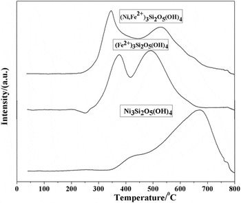
The TPR analysis indicates the degree of metallic phase present after activation and heat treatment of the catalysts. As shown in Fig. 6, the shape of TPR profiles assigned the information about the nature of Ni and Fe species. The TPR profiles of Ni3Si2O5(OH)4 and Fe2+ 3(Si2O5)2(OH)2 were also presented for comparison purpose. The TPR profile of Ni3Si2O5(OH)4 showed mainly a single reduction peak centered at around 670 °C with a shoulder-like reduction peak about 400 °C. The lower temperature reduction peak was ascribed to the conversion of bulk nickel silicate. The intense high temperature reduction peak at around 670 °C was due to the reduction of nickel silicate into Ni0. H2-TPR profiles of (Ni,Fe2+)3Si2O5(OH)4 and Fe2+ 3(Si2O5)2(OH)2 both showed 2-stage reduction behavior. In the TPR profile of Fe2+ 3(Si2O5)2(OH)2, the first reduction temperature peak about 370 °C was ascribed to the reduction of small Fe silicate particles. However, the second reduction peak had higher temperature due to agglomeration of Fe species for its magnetism to form larger particles. H2-TPR profile of (Ni,Fe2+)3Si2O5(OH)4 showed a 2-stage reduction behavior similar to Fe2+ 3(Si2O5)2(OH)2. Initially, a low temperature reduction peak had T max about 350 °C, which corresponded to the first reduction of Fe species. Obviously, a shift in the first temperature peak was observed toward lower temperature compared with the TPR profile of Fe2+ 3(Si2O5)2(OH)2, which may be ascribed to the interaction of Ni2+ and Fe2+. The same reason suitable for the second peak shifted to lower temperature compared with the TPR profile of Ni3Si2O5(OH)4. According to the previous report, Reference Ashok, Reddy, Raju, Subrahmanyam and Venugopal39 the presence of Fe2+ in (Ni,Fe2+)3Si2O5(OH)4 may produce spillover hydrogen, which considerably accelerated the nucleation of the Ni metal in these reduction conditions and enhanced the reducibility of Ni at considerably lower temperature.
TPR profiles of (Ni,Fe2+)3Si2O5(OH)4, (Fe2+)3(Si2O5)2(OH)2, and Ni3Si2O5(OH)4 microspheres.

E. BET of (Ni,Fe)3Si2O5(OH)4 and Ni–Fe/SiO2 microspheres
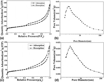
The reduction under the hydrogen atmosphere at 650 °C according to temperature programmed reduction (TPR) for 5 h, bimetallic catalyst Ni–Fe/SiO2 hollow microspheres were obtained. The N2 adsorption/desorption isotherm of (Ni,Fe)3Si2O5(OH)4 hollow microspheres (unreduced) and bimetallic catalyst Ni–Fe/SiO2 hollow microspheres (reduced) were investigated. As shown in Fig. 7, the isotherm is identified as type IV hysteresis loop, which is the characteristics of mesoporous materials. The Brunauer–Emmett–Teller (BET) surface area of (Ni,Fe2+)3Si2O5(OH)4 hollow microspheres and Ni–Fe/SiO2 hollow microspheres were measured to be 263 m2/g, 80.0 m2/g, and total pore volume of both samples 0.878 cm3/g, 0.270 cm3/g respectively. The average diameter of the pores for (Ni,Fe2+)3Si2O5(OH)4 hollow microspheres (before reduction) and Ni–Fe/SiO2 (after reduction) were 2.6 nm and 13.5 nm, respectively. It can be seen from the above data that after reduction, the surface area and pore volume decreased, however, the average pore size increased. This was because the reduction reaction under the high temperature heat treatment may lead to the collapsing of parts of the small pores in nanosheets and alloy or metal particles gathering easily for the strong magnetism of the iron particles.
N2 Adsorption/desorption isotherms of bimetallic (Ni,Fe2+)3Si2O5(OH)4 hollow microspheres (a, unreduced) and bimetallic catalyst Ni–Fe/SiO2 hollow microspheres (c, reduced), and pore diameter distribution of bimetallic (Ni,Fe2+)3Si2O5(OH)4 hollow microspheres (b, unreduced) and bimetallic catalyst Ni–Fe/SiO2 hollow microspheres (d, reduced).

To investigate the different structure affecting on the catalytic hydrogenation of the nitrobenzene, different products at different reaction conditions were prepared. The reaction conditions of Ni–Fe-1 silicate core–shell microspheres and Ni–Fe-2 silicate hollow microspheres were 140 °C–12 h and 140 °C–24 h + 180 °C–12 h respectively, and the corresponding reduced products were marked as Ni–Fe-1/SiO2 and Ni–Fe-2/SiO2.
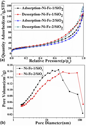
The N2 adsorption/desorption isotherms of Ni–Fe-1/SiO2 core–shell microspheres and Ni–Fe-2/SiO2 hollow microspheres were also investigated. As shown in Fig. 8, the Brunauer–Emmett–Teller (BET) surface area of Ni–Fe-1/SiO2 core–shell microspheres and Ni–Fe-2/SiO2 hollow microspheres were measured to be 90.2 m2/g, 80.0 m2/g, and total pore volume of both samples 0.23 cm3/g, 0.27 cm3/g respectively. The average diameter of the both pores reduced products were 10.2 nm and 13.5 nm, respectively. Thus it can be seen that prolonging the reaction time affected a little on the surface properties of the microspheres.
N2 adsorption/desorption isotherms of Ni–Fe-1/SiO2 core–shell microspheres and Ni–Fe-2/SiO2 hollow microspheres (a), and pore diameter distribution of Ni–Fe-1/SiO2 core–shell microspheres and Ni–Fe/SiO2 hollow microspheres (b), the reaction condition: Ni–Fe-1 silicate (140 °C–12 h), Ni–Fe-2 silicate (140 °C–24 h + 180 °C–12 h).

F. Catalytic property
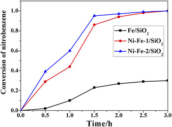
Bimetallic catalysts Ni–Fe/SiO2 reduced in situ under the hydrogen atmosphere possess catalytic property, which can be evaluated by the hydrogenation of nitrobenzene at 373 K and 3.0 MPa. The catalysts used on the hydrogenation of the nitrobenzene have been widely reported in many papers, Reference Macías Pérez, Salinas Martínez de Lecea and Linares Solano9–Reference Wang, Yuan, Nie, Hou and Zheng17 however their industrial application is limited due to the scarce resources or higher reaction conditions to reach a satisfied selectivity of aniline. Here, in the paper the highly active catalyst prepared with the economic materials and facial process at mild reaction conditions was obtained. The conversion of nitrobenzene was shown in Fig. 9.
Conversion of nitrobenzene of different catalysts for nitrobenzene hydrogenation.

Ni–Fe-1/SiO2 core–shell microspheres, Ni–Fe-2/SiO2 hollow microspheres and Fe/SiO2 core–shell microspheres were obtained using corresponding metal silicate reduced in situ under the hydrogen atmosphere. The conversion of nitrobenzene attained 94%, 96%, and 12% using Ni–Fe-1/SiO2 core–shell microspheres, Ni–Fe-2/SiO2 hollow microspheres and Fe/SiO2 core–shell microspheres as catalysts within 2 h, respectively. When the catalytic time prolonged to 3 h, the conversion of nitrobenzene reached 100% except Fe/SiO2. It is necessary to indicate that Ni–Fe-2 silicate hollow microspheres and iron silicate core–shell microspheres had been prepared with the same method and the same reaction conditions. Bimetallic Ni–Fe-1/SiO2 core–shell microspheres and Ni–Fe-2/SiO2 hollow microspheres exhibited the higher catalytic performance than monometal Fe/SiO2 core–shell microspheres, which indicated that the existence of Ni particles played an important role. The Ni–Fe bimetallic could form some galvanic cells, and Fe passed electrons to the catalytic Ni, which played an important role in the increase of Fe corrosion and dechlorination activity. Reference Zhang, Quan and Zhang40 The metal iron was rarely used as the catalyst on the nitrobenzene hydrogenation. The low dechlorination efficiency over the pure Fe particles demonstrated that direct dechlorination of 4-CP was difficult to occur without the catalytic Ni. The addition of Ni significantly increased the dechlorination of 4-CP due to the mechanism of catalytic hydrogenation. Reference Xu, Deng, Xu, Zhang, Wu, Wang, Huang and Yu41
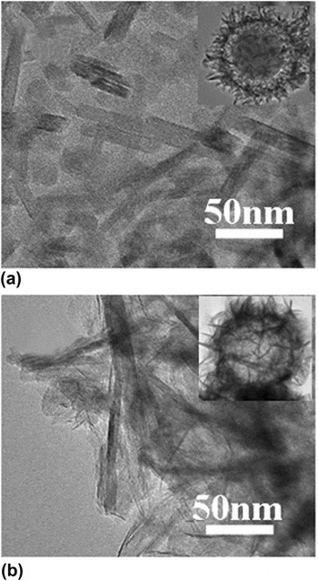
The conversion of nitrobenzene of Ni–Fe-1/SiO2 core–shell microspheres and Ni–Fe-2/SiO2 hollow microspheres was different within 2 h. Along with the hydrogenation time prolonging to 3 h, the difference disappeared. The difference in the nitrobenzene hydrogenation may be explained as follows. Firstly, the nickel contents in Ni–Fe-1/SiO2 core–shell microspheres and Ni–Fe-2/SiO2 hollow microspheres obtained by inductively coupled plasma atomic emission spectroscopy (ICP-AES) were 97.3 mg/g and 163 mg/g, respectively, the higher the nickel content, the better the catalytic activity. Secondly, there were some difference between the morphology of Ni–Fe-1/SiO2 core–shell microspheres and Ni–Fe-2/SiO2 hollow microspheres. As shown in Fig. 10, the nanosheets in the Ni–Fe-1/SiO2 core–shell microspheres were arranged more orderly than that in the Ni–Fe-2/SiO2 hollow microspheres, which may cause more active sites in the lower nickel content catalyst because of the more order bareness surface. Thus the different nickel content combined with the morphology could make the difference of the catalytic properties lower between the above-mentioned catalysts. In comprehensive consideration of the conversion of the nitrobenzene hydrogenation and the economy of the reaction, Ni–Fe-1/SiO2 core–shell microspheres are chosen as the most practical catalyst in the hydrogenation of nitrobenzene.
TEM micrographs of Ni–Fe-1/SiO2 core–shell microspheres (a) and Ni–Fe-2/SiO2 hollow microspheres (b).

IV. CONCLUSION
A simple, effective, versatile method has been used for the synthesis of controlled morphology of bimetallic (Ni,Fe2+)3Si2O5(OH)4 hollow microspheres. The formation of the different morphology may be due to the synergistic effect of nickel ion and iron ion. Because of synergistic effect of nickel ion and iron ion, the reaction conditions of the chosen catalyst with higher activity were decreased from 140 °C–24 h + 180 °C–12 h for iron silicate hydroxide to 140 °C–12 h. Different catalysts including Ni–Fe-1/SiO2 core–shell microspheres, Ni–Fe-2/SiO2 hollow microspheres and Fe/SiO2 core–shell microspheres were prepared using in situ reduction under the hydrogen atmosphere and their catalytic property had been studied. Ni–Fe-1/SiO2 core–shell microspheres under a mild synthetic conditions had more activity as catalyst than Fe/SiO2 with a conversion of nitrobenzene reaching 94% within 2 h, which is 82% higher than Fe/SiO2.
Supplementary Material
To view supplementary material for this article, please visit https://doi.org/10.1557/jmr.2016.521.
ACKNOWLEDGMENTS
This work was supported by the National Natural Science Foundation of China (51272115) and A Project of Shandong Province Higher Educational Science and Technology Program (J13LA10).