I. INTRODUCTION
Fractals bow parade is an awfully fascinating chattel acknowledged as self-similarity. If you scrutinize specifically the niceties of a fractal arch, it materializes to facilitate a scrap of the arc that replicates unerringly the intact camber but on a pole apart range. Several of these curls are recognized as the Von Koch's snowflake or else the triangle of Sierpinski [Reference Kumar and Singh1]. Spontaneously, fractals canister can be seen as a camber moderately substantial with a two-dimensional vicinity. These curls are habitually portrayed as a space-filling arch. To accomplish extra mass drop in the antenna drawing, metamaterial base practice is measured. Metamaterials are non-natural material, which encloses the curious property such as pessimistic permittivity and pessimistic permeability [Reference Cai, Qian, Ciao, Zhang and Yang2, Reference Elavarasi and Shanmuganantham3]. With these properties, energy characteristics such as bandwidth enrichment, extent cutback, and notch concert can be achieved in microwave strategy. Awfully a small number of literatures are at hand in the mixture of fractal base sculpts with split ring resonator (SRR) [Reference Si, Zhu and Sun4, Reference Naser-Moghadasi, Ali Sadeghzadeh, Khajeh Mohammad Lou, Singh Virdee and Aribi5].
In this paper, a squashed complementary triangular split ring resonator (CTSRR)-loaded multiband projection is planned for multiband action. A monopole mast with Sierpinski gasket iterations along with balancing triangular SRR is used as a blistering element [Reference Thankachan and Chandran6, Reference Mishra and Pandey7]. To realize further mass diminution at superior frequencies, a triangular SRR configuration is laden at the support plane of the antenna [Reference Zarghooni, Dadgarpour and Denidni8]. The anticipated device covers wireless local area network (WLAN) 5.72 GHz and fixed satellite (Earth-to-space) 14.3 GHz along with (ITU), and 16.06 GHz concurrently. It has a condensed formation and emission personality in the preferred occurrence bands [Reference Seladji-Hassaine and Bendimerad9, Reference Dawar, Raghava and De10].
II. SRR FRACTAL ANTENNA
A) Metamaterial
Metamaterial is a synthetic matter that reveals electromagnetic (EM) reaction akin to pessimistic permittivity along with pessimistic permeability, which is not institute in nature offered substance. An SRR is one of the frequent metamaterial configurations. They outline the origin on behalf of the tininess of antennas. Conservative antennas necessitate to being at least partially the magnitude of the wavelength. Enclosure of metamaterial vastly trims down the size. SRR is an amalgamated metamaterial. It consists of concentric rings wrecked of non-magnetic objects (at this juncture, copper) estranged by a fissure, which yields discretionary pessimistic magnetic permeability [Reference Elavarasi and Shanmuganantham3].
B) Sierpinski Gasket – geometric method
In 1916, the renowned Sierpinski gasket was formulated by Waclaw Sierpinski who is a glisten mathematician. The Sierpinski gasket course of action as pursue,
-
• The preliminary direct is a triangle.
-
• Segregate its three elevations in two fragments of equivalent span.
-
• Unite the midpoint to unearth four interior triangles furthermore to tint the three exterior ones.
-
• Concern the matching progression to the hush-hush triangles, although the hub one.
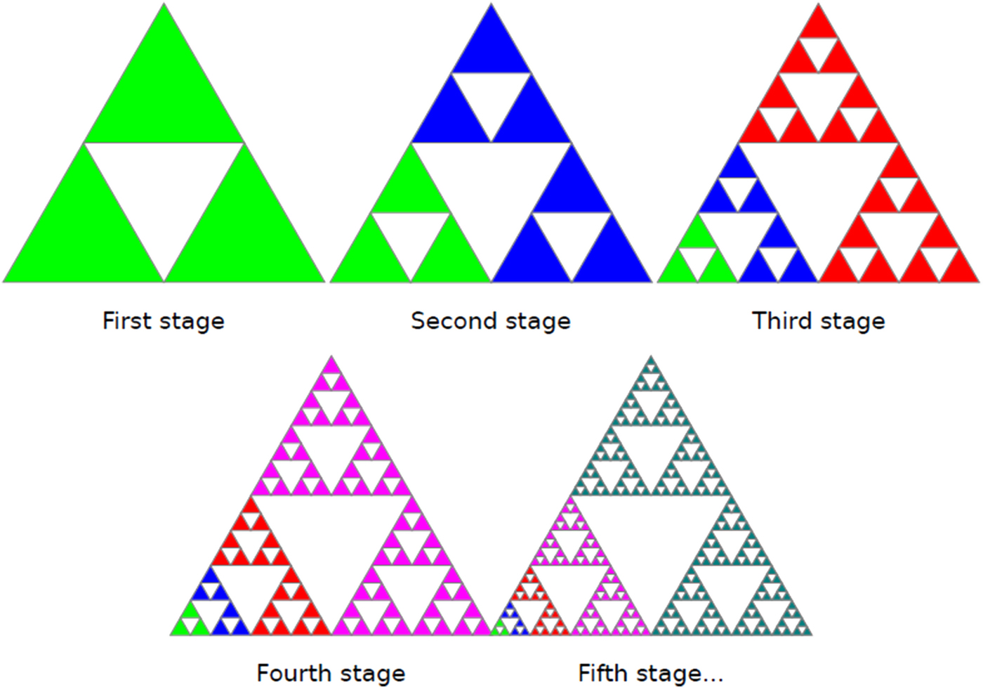
The earliest iterations furnish the tag along picture (Fig. 1):
Iterations of Sierpinski gasket.

1) CURVE LENGTH
Spontaneously, the extent of the Sierpinski gasket is the full amount of the distance end to end of all the slices requisite to sketch the entity.
Estimate,
S – Side length of the preliminary triangle as entity length.
3S – Boundary of the triangle.
As the numeral of iteration augments, the arch length tends to perpetuity while it is sheltered in a void area [Reference Mishra and Pandey7].
2) CURVE AREA
Foremost, judge the locale of the original equilateral triangle as entity vicinity. Throughout the opening iteration, we get hold of four private triangles; both boast a quarter identical to one cut up of the vicinity of the tale triangle. Since the core one is gone unpainted, the full amount area of the Sierpinski that bends behind the initial iteration is 3/4 of the unique area. Pertaining to the similar practice on apiece with three enduring triangles, we dig up nine tinted triangles, apiece single enclose 1/16 of the imaginative area. The whole vicinity at this instant is 9/16 of the inventive area. At countless iteration, the curl area congregates on the road to zero, connotation to facilitate the Sierpinski gasket encompass denial area.
The same area preserves to be uttered like:
 $${\rm Area} = (3/4)^n, $$
wherever n is the iteration numeral.
3) FRACTAL DIMENSION
The fractal dimension is toiled out by means of the Hausdorff–Besicovitch equation:
 $${\rm Dimension} = {{\log (n)} / {\log (r)}}.$$
Sierpinski Triangle–Hausdorff–Besicovitch equation bestow, reinstate N via three (as both iterations fashion three self-similar triangles) along with r via two (as the surface of the triangles be alienated by means of two).
Let, N n , number of uninvolved triangles for iteration n; L n , length of a triangle side; A n , fractional area that is detached from the n th iteration.
Then,
 $$N_n = 3^n,$$
 $$L_n = \left( {\displaystyle{1 \over 2}} \right)^n ;\;L_n = 2^{ - n},$$
 $$A_n = (L_n )^2 (N_n ) = \left( {\displaystyle{3 \over 4}} \right)^n,$$
 $$D = \log {{(3)} / {\log (2) = {\rm 1}{\rm. 5849625}}}.$$
III. SGF-TSRR ANTENNA PATTERN
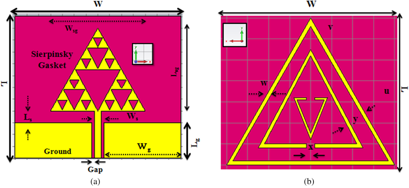
The geometry of the anticipated antenna is exposed in shape 1. It is fabricated resting on 1.6-mm thick FR-4 epoxy substrate by way of relative permittivity of 4.4, moreover on the whole aspect to be merely 12 × 14 mm2. The emission building block of the triple band antenna minimally in control consists of a metamaterial edifice that embraces a triangular split-ring configuration with one closed and two non-opposite slits in both halos, which are relocated. Gap among the slit on both sides of the center remnants remain stable. It is fed by a CPW line, which can be allied by an Sub Miniature Antenna (SMA). Optimum parameter is given in Figs 2(a) and 2(b).
(a) Evolution of the antenna projected (top view) (W, L, Wg, Lg, Ws, Ls, Wsg, Lsg, h – 12, 14, 6.5, 3, 0.6, 1, 7, 7, 1.6). (b) Evolution of the antenna projected (bottom view) (U, v, w, x, y – 7, 7, 0.3, 0.3, 1).

IV. SIMULATED ALONG WITH MEASURED RESULTS
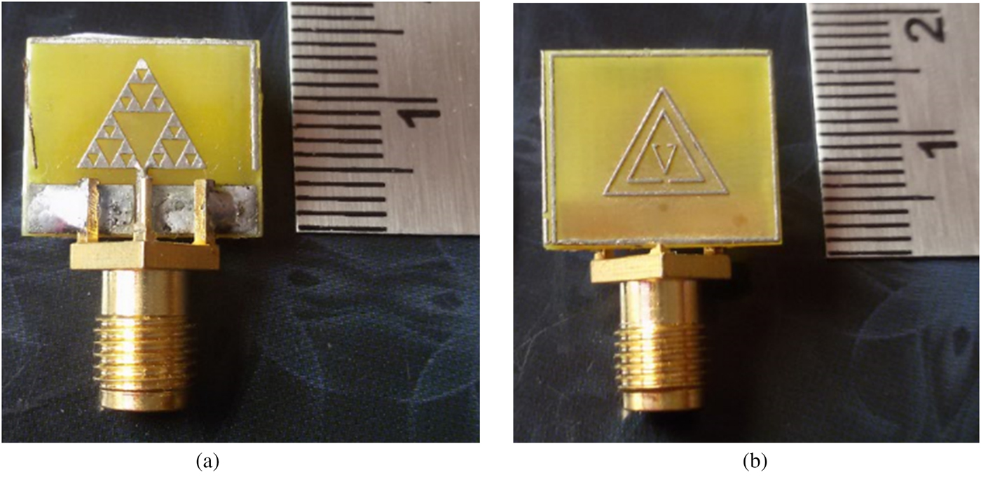
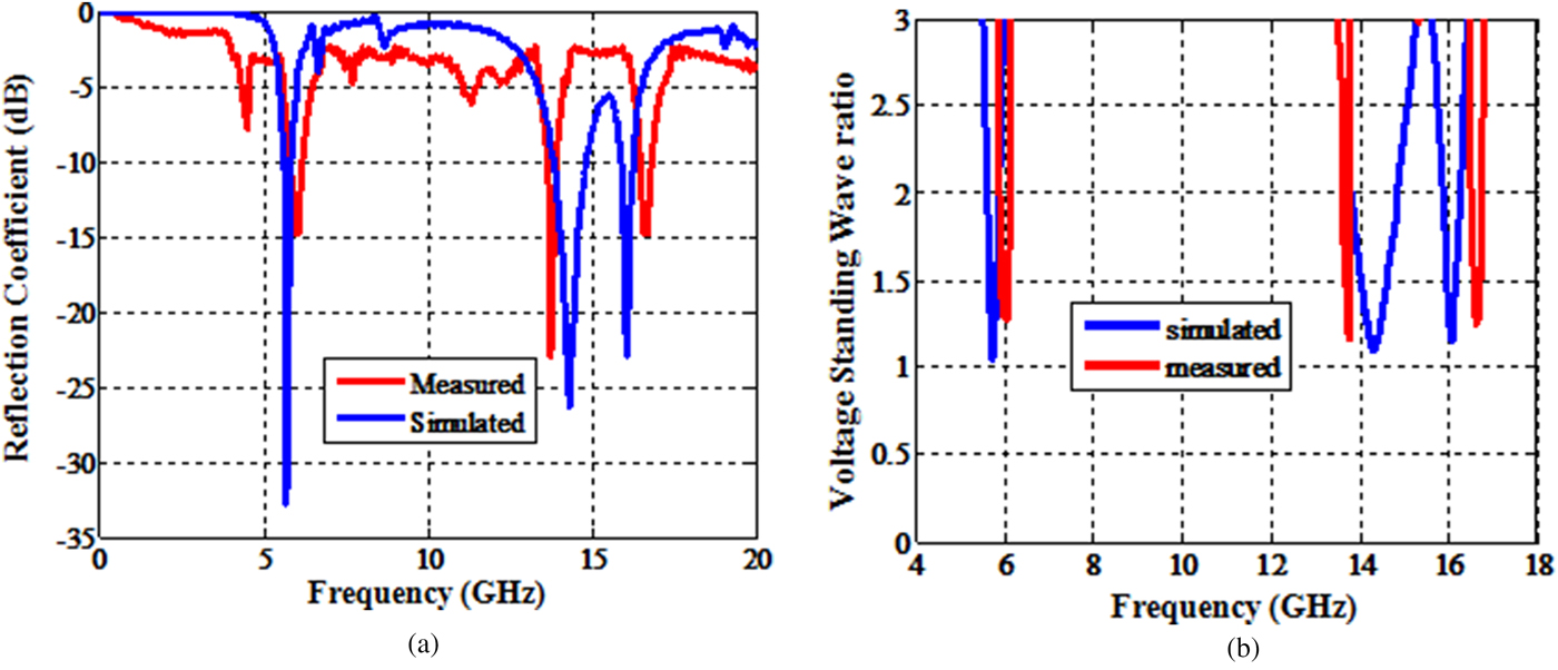
An archetype of the anticipated wideband tentacle is fabricated and calculated, and its snap of top and reverse view is made known in Figs 3(a) and 3(b). The return trouncing of the tri-frequency mast is measured via Agilent E5071C vector network analyzer. The virtual as well as deliberated return losses aligned with frequency of this antenna are prearranged into Fig. 4(a). It preserves that the simulated as well as measured fallout to be evidence for level-headed consistency, and the S11 frequency is <−10 dB. The antenna shows the resonances at 5.72 GHz (Bandwidth (BW): 5.5–6.0) at −32.81 dB covering WLAN −5 GHz (802.11 a/h/j/n/ac)/C band, 14.3 GHz (BW: 13.82–150) at −26.38 dB casing fixed satellite/Ku band, 16.06 GHz (BW: 15.88–16.5) at −22.87 dB casing ITU/Ku band. The trivial incongruity owes not only to the outcome of the SMAs worn but also the tolerances through manufacture. The Voltage Standing Wave Ratio (VSWR) is tested to be beneath 2 characteristically as publicized in the Fig. 4(b). So the antenna proposed is a hopeful contender for outlook cohort hand-held transportable plans.
Fabricated SGF-SRR top and flipside view.

Simulated and measured S11/VSWR.

The comparison among area and resonance of the proposed antenna with a few published literatures is given in Table 1.
Comparison between proposed and existing literatures.

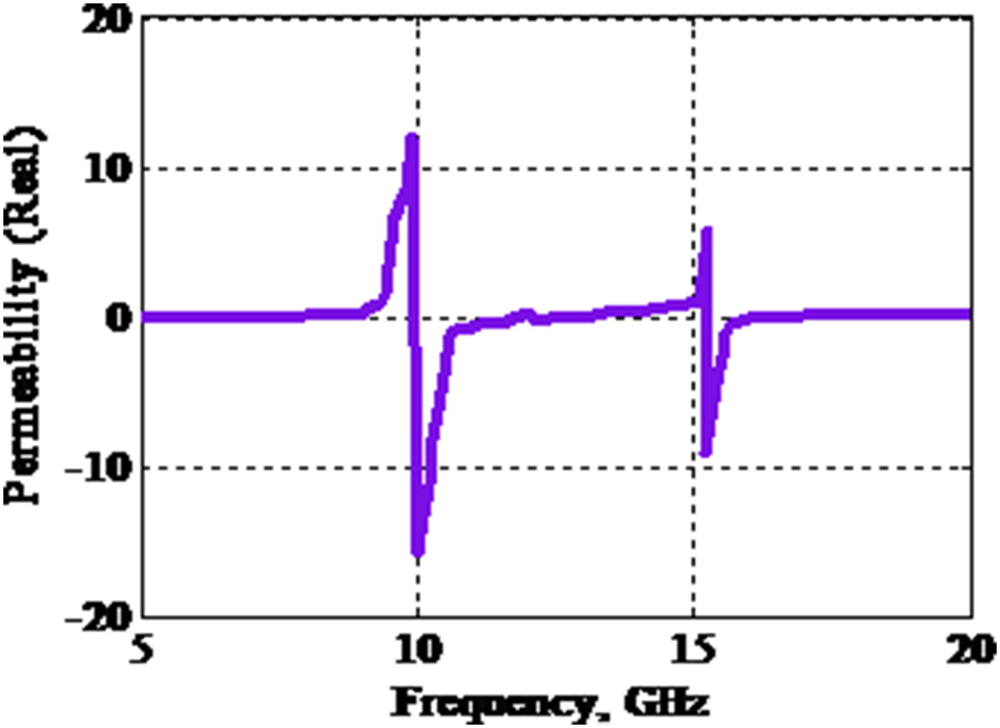
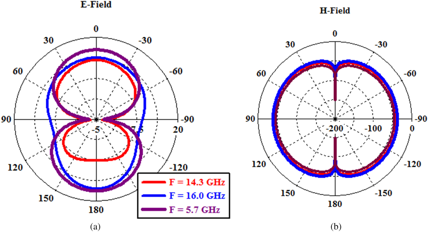
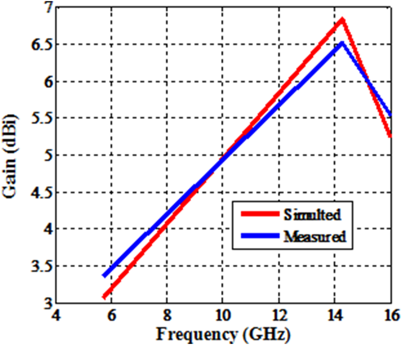
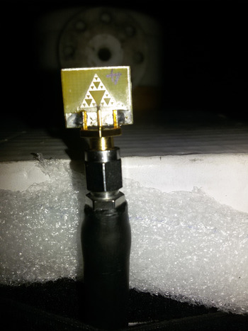
For realistic testing, the triangular split ring resonator (TSRR) has to be kept back within the waveguide medium. An EM wave is an occurrence throughout one port and the consequent negative permeability can be deliberated to repossess the effective constraints. The retrieved negative permeability of the SRR antenna is publicized in Fig. 5. It resonates at two frequencies of 10 and 15.2 GHz, where the notches are formed. The measured far-field pattern is revealed in Fig. 6, whereas the gain is achieved beyond 2 dBi, routinely as publicized in Fig. 7. The resonant frequencies 5.7, 14.3, and 16 GHz are sampled in the process of simulation and measured. As the Sierpinski gasket fractal (SGF)-TSRR antenna achieves three multiple frequencies, that particular frequency of the gain is achieved beyond 2 dBi. The SGF-SRR antenna shows signs of the omnidirectional energy outline at an H-plane with bidirectional energy mold at the E-plane. SGF-TSRR antenna in anechoic chamber is shown in Fig. 8. The split of the antenna is furthermore experimentally unwavering, plus it has brought into being as the antenna is polarized beside X-axis pro tri-band maneuver.
Extracted negative permeability of SSRR.

Measured far-field patterns.

Simulated and measured gain.

Snap of SGF-TSRR antenna in anechoic chamber.

V. CONCLUSION
The shot paying attention on the scrutiny and intend parameter of SGF metamaterial enthused CPW patch antenna. An exceedingly compacted tri-band antenna with a CT-SRR is deliberate and premeditated. In this dispatch, we investigate improvization on SGF-SRR style as well as it puts on show instantaneous recital in tri-bands. The frequency bands are centered at 5.72 GHz at C band (4–8 GHz), 14.3 and 16.06 GHz at Ku band (12–18 GHz). With the magnification of Sierpinski gasket plus by alteration of the CTSRR, multiband application will pull off and that can be utilized in assorted communication systems in LTE2300, fixed satellite, and WiMAX.
 C. Elavarasi received her B.E. degree, in Electronics and Communication Engineering in 2012, and M.E. degree in Communication Systems in 2014 from Anna University, Chennai. She is currently working toward Ph.D. degree at the Department of Electronics Engineering, School of Engineering and Technology, Pondicherry University (Central University), Puducherry, India. She has authored eight journals and conference papers. Her research interests include microwave and millimeter wave antennas, fractal antennas, and metamaterial-split ring resonator antennas.
 Dr. T. Shanmuganantham received his B.E. degree in Electronics and Communication Engineering from University of Madras in the year 1996, and M.E. degree in Communication Systems from Madurai Kamaraj University in the year 2000 and Ph.D. (received with Gold Medal) in the area of Antennas from the National Institute of Technology, Tiruchirappalli in the year 2010 under the guidance of Professor S. Raghavan. He has been an Assistant Professor in the Department of Electronics Engineering, School of Engineering and Technology, Pondicherry Central University, Pondicherry, since July 2010. His research interest includes antennas, microwave/millimeter-wave engineering, and MEMS/NEMS. He has published 250 research papers in various national- and international-level journals and conference proceedings. He has been a reviewer for major journals including the IEEE Transactions on Antennas and Propagation. He has completed two sponsored projects worth of Rs. 57 lakhs. He is elected as Fellow in Antenna Test and Measurement Society and a senior member in IEEE, member in Antennas and Propagation Society, Circuits and System Society, life member in Applied Computational Electromagnetic Society, Society of EMC, ISSS, IETE, IE (India), CSI (India), OSI, ILA, ISI, and ISTE. He is serving as office bearer for IEEE Circuits and Systems Society (India Chapter) and also he is a member of Board of Studies in Pondicherry University, University of Madras, and Annamalai University. His biography was included in “Marquis who is who in the world” USA in 2011.