I. INTRODUCTION
Many wireless power transfer (WPT) methods have been suggested and examined in the past for various practical applications. In fact, WPT has been achieved using near-field coupling in various applications such as Radio Frequency Identification (RFID) tags, telemetry, and implanted medical devices (IMD) [Reference Finkenzeller1, Reference Nikitin, Rao and Lazar2]. In addition, certain inductive coupling techniques have been reported to show high power transfer efficiencies (of the order of 90%) for very short distances (1–3 cm) [Reference Vandevoorde and Puers3]. However, the efficiency of such techniques drops drastically for longer distance since it decays as 1/r Reference Kurs, Karalis, Moffatt, Joannopoulos, Fisher and Soljacic6 [Reference Balanis4, Reference Mazlouman, Mahanfar and Kaminska5].
This paper focuses on the optimal design of spiral resonators that maximize the efficiency of strongly coupled magnetic resonance (SCMR) systems. The SCMR method is a non-radiative wireless mid-range power transfer method (10–300 cm) that has been recently developed [Reference Kurs, Karalis, Moffatt, Joannopoulos, Fisher and Soljacic6–Reference Cook, Meier, Sieber, Secall and Widmer10]. Recent work has also shown that SCMR provides WPT efficiencies that are significantly greater than the efficiencies of traditional inductive coupling methods [Reference Kurs, Karalis, Moffatt, Joannopoulos, Fisher and Soljacic6, Reference Kurs, Karalis, Moffatt and Soljacic Marin7, Reference Karalis, Kurs, Moffat, Joannopoulos, Fisher and Soljacic11]. In order for SCMR to achieve high efficiency, the TX and RX elements (typically loops or coils) are designed to resonate at the desired operational frequency, which must coincide with the frequency at which the elements exhibit maximum Q-factor. This paper analytically derives the conditions that must be satisfied by the geometrical parameters of spiral resonators in order for SCMR systems to achieve optimal efficiency.
II. WPT WITH SCMR
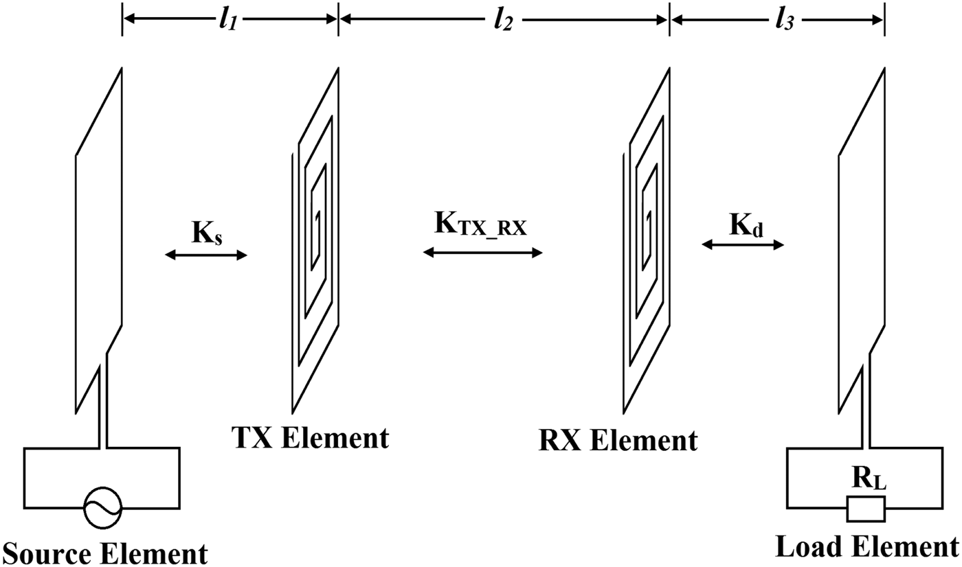
SCMR systems use resonant transmitters and receivers that are strongly coupled. Strongly coupled systems are able to transfer energy efficiently, because resonant objects exchange energy efficiently versus non-resonant objects that only interact weakly [Reference Kurs, Karalis, Moffatt and Soljacic Marin7]. A standard SCMR system consists of four elements (typically four loops, or two loops and two coils). Here, an SCMR system based on spirals is shown in Fig. 1. The source element is connected to the power source, and it is inductively coupled to the TX element. The TX element must exhibit a natural resonance frequency that is identical to the RX. Both elements should be resonant at the frequency, where their Q-factor is naturally maximum. Furthermore, the load element is terminated with a load. For our analysis, we assume that the entire system operates in air.
Schematic representation of an SCMR system with spirals in the air, where K S, K TX_RX, and K d are the respective coupling coefficients.

III. OPTIMAL SCMR BASED ON SPIRAL STRUCTURES
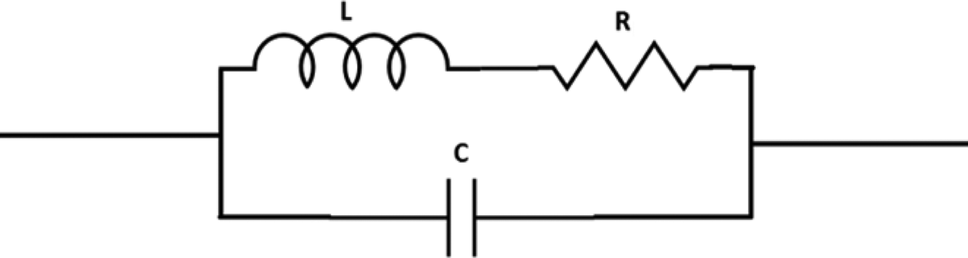
In this section, we will develop the guidelines for designing optimal SCMR systems that use spiral TX and RX resonators. The TX and RX resonators shown in Fig. 1 can be equivalently represented by an Resistor Inductor Capacitor (RLC) circuit shown in Fig. 2. Helices and spirals are often preferred as SCMR TX and RX resonators as they exhibit both distributed inductance and capacitance thereby requiring no external capacitors to tune to the self-resonance frequency. Also, external capacitors have losses, which in practice can reduce the Q-factor of the TX and RX elements and in turn decrease the efficiency of SCMR systems.
RLC representation of a spiral.
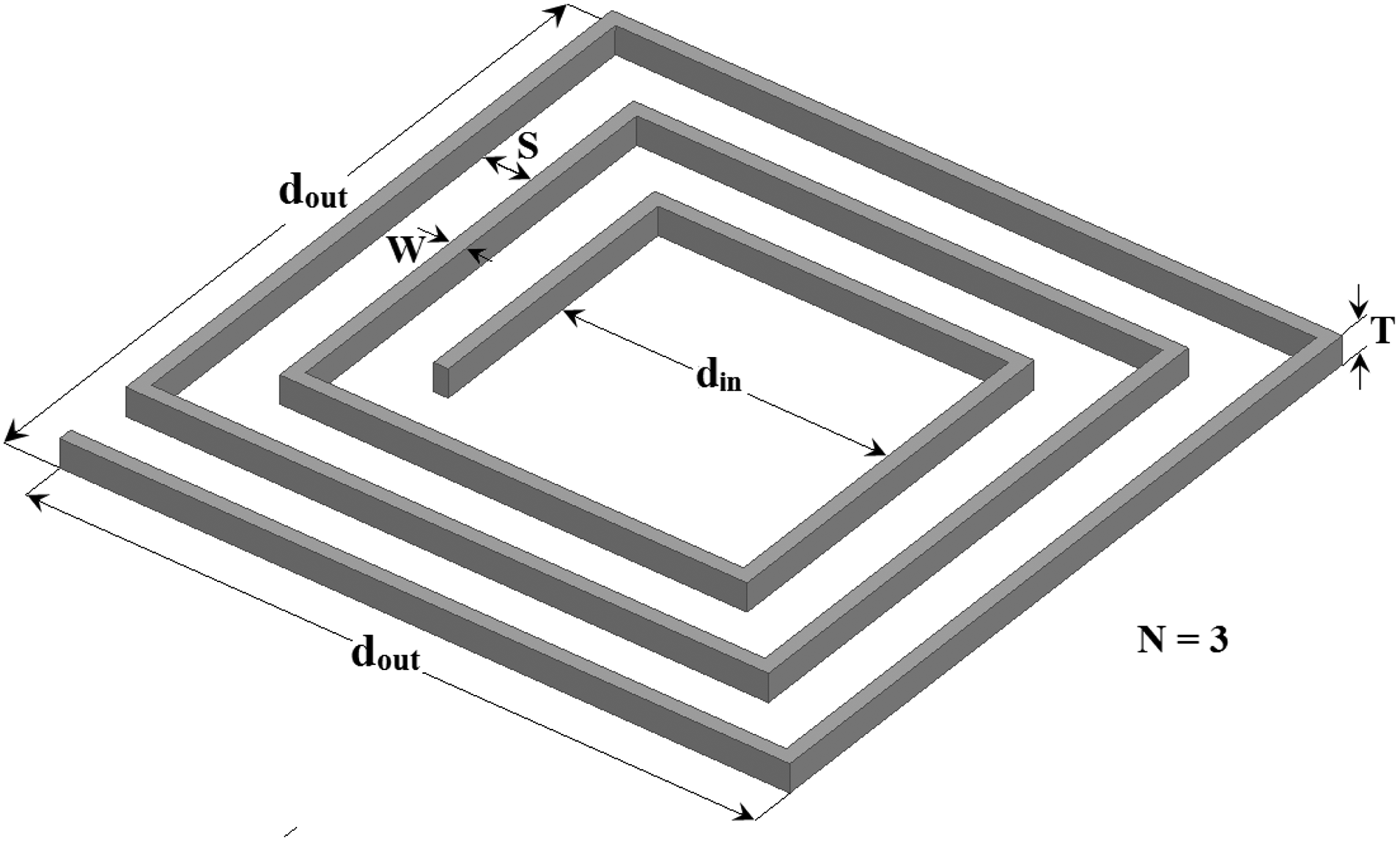
Figure 2 shows a square spiral with a rectangular cross-section. The basic dimensional parameters of such spiral are N, W, S, T, and d out, which are the number of turns, cross-sectional width, spacing between turns, thickness of the trace material, and the outermost side length of the spiral, respectively, are used for the analysis of the SCMR system (Fig. 3).
The spiral model geometry.
The inner diameter, d in, is derived from the other parameters as:
 $$d_{in}=d_{out} - 2\left[{NK - S} \right]\comma \;$$
where K = W + S is the distance between the centers of two adjacent turns. The total length ℓtot of the spiral can be calculated as:
 $$\ell _{tot}=4N\left[{d_{out} - K\left({N - 1} \right)} \right].$$
The resonance frequency of the spiral f r can be calculated from [Reference Balanis4]:
 $$f_r=\displaystyle{1 \over {2\pi \sqrt {LC} }}.$$
The resonant frequency f r is also the operational frequency for the SCMR wireless powering system. The Q-factor at the resonance frequency can be written as [Reference Mohan, Hershenson, Boyd and Lee12]:
 $$Q=\displaystyle{{2\pi f_r L} \over {R_{ohm}+R_{rad} }}\comma \;$$
where L, R ohm, and R rad are the self-inductance, ohmic resistance and radiation resistance of the spiral. The inductance L of a spiral can be written as [Reference Joannopoulos, Karalis and Soljacic13]:
 $$L=\left[{\displaystyle{{\mu _o N^2 \left({\displaystyle{{d_{in}+d_{out} } \over 2}} \right)c_1 } \over 2}} \right]\left[{\ln \left({\displaystyle{{c_2 } \over \alpha }} \right)\, +c_3 \alpha+c_4 \alpha ^2 } \right]\comma \;$$
where c 1 = 1.27, c 2 = 2.07, c 3 = 0.18, and c 4 = 0.13, are the constants derived based on the geometrical layout of the square spiral; and α is the fill ratio defined by α = (d in − d out)/(d in + d out). The ohmic and radiation resistances can be written as [Reference Balanis4, Reference Joannopoulos, Karalis and Soljacic13]:
 $$R_{ohm}=\displaystyle{{\ell _{tot} } \over {4\sqrt {WT} }}\sqrt {\pi \mu _o \rho f} \; \left({1+\displaystyle{{R_p } \over {R_o }}} \right)\comma \;$$
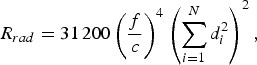 $$R_{rad}=31\, 200\left({\displaystyle{f \over c}} \right)^4 \left({\sum\limits_{i=1}^N {d_i ^2 } } \right)^2\comma \;$$
where, d i is the side length of the ith turn of spiral, ρ is the spiral's conductor resistivity, c is the speed of light, and  $\sqrt {\pi \mu _o \rho f} \; $ represents the conductor's sheet resistance [Reference Balanis4]. The factor R p/R o in (6) represents the proximity effect factor that accounts for the additional resistance due to closeness of the conductors. The proximity factor depends on W, S, and N and adds additional resistance that is undesirable as it reduces the Q-factor. Hence, the spiral dimensions have to be chosen carefully to maximize the Q-factor. Specifically, the proximity factor can be significantly reduced by increasing the spacing between turns, S, and decreasing the width, W, (S > 10W) [Reference Smith14]. In order to derive analytical expressions for Q max and f max, the analytical and simulation setups are chosen such that the proximity effect is negligible reducing (6) to:
 $$R_{ohm}=\displaystyle{{\ell _{tot} } \over {4\sqrt {WT} }}\sqrt {\pi \mu _o \rho f} \;.$$
It should also be noted that (4)–(8) are effective in SCMR analysis only when ℓtot < λ/3 [Reference Balanis4]. The Q-factor of a resonant spiral can be expressed in terms of its geometrical parameters using (4), (5), (7), and (8) as:
 $$Q=\displaystyle{{\pi f_r \mu _o N^2 \left({\displaystyle{{d_{in}+d_{out} } \over 2}} \right)c_1 \left[{\ln \left({\displaystyle{{c_2 } \over \alpha }} \right)\, +c_3 \alpha+c_4 \alpha ^2 } \right]} \over {\displaystyle{{\ell _{tot} } \over {4\sqrt {WT} }}\sqrt {\pi \mu _o \rho f_r }+31\, 200\left({\displaystyle{{f_r } \over c}} \right)^4 \left({\sum\limits_{i=1}^N {d_i ^2 } } \right)^2 }}\,.$$
The maximum possible Q-factor Q max of a spiral and the frequency f max, where Q max occurs, can be derived from (9) using standard calculus as:
 $$f_{max}=120.44 \times 10^6 \left[{\displaystyle{{\ell _{tot} \sqrt {\mu _o \rho } } \over {\sqrt {WT} \left({\mathop \sum \nolimits_{i=1}^N d_i ^2 } \right)^2 }}} \right]^{2/7}.$$
 $$Q_{max}=\displaystyle{{\pi f_{max} \mu _o N^2 \left({\displaystyle{{d_{in}+d_{out} } \over 2}} \right)c_1 \left[{\ln \left({\displaystyle{{c_2 } \over \alpha }} \right)\, +c_3 \alpha+c_4 \alpha ^2 } \right]} \over {\displaystyle{{\ell _{tot} } \over {4\sqrt {WT} }}\sqrt {\pi \mu _o \rho f_{max} }+31200\left({\displaystyle{{f_{_{max} } } \over c}} \right)^4 \left({\sum\limits_{i=1}^N {d_i ^2 } } \right)^2 }}.$$
Equations (10) and (11) were derived assuming the proximity effect is negligible; therefore, they are valid only when S ≥ 10W. A similar work was done in [Reference Jow and Ghovanloo15] with spirals for resonant inductive coupling and not SCMR, in which the proximity and radiation resistance are ignored.
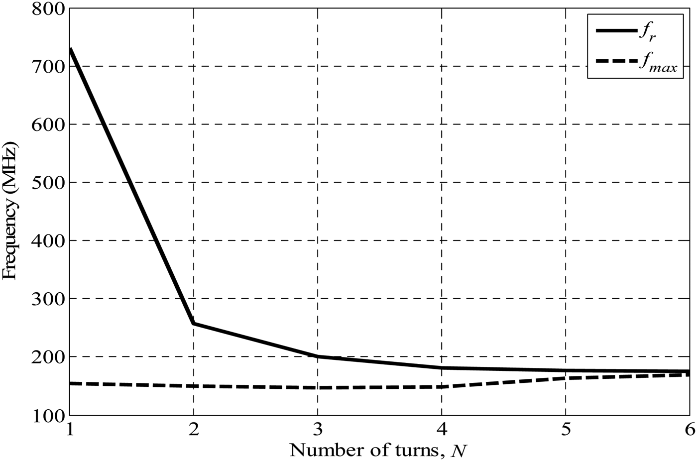
SCMR requires that each of the TX and RX spiral elements exhibit maximum Q-factor at a frequency f max = f r, in order to achieve maximum power transfer efficiency (i.e. f r = f max). This condition may not be naturally satisfied. This means that if we use (10) to design an SCMR system with spirals that have a certain f max that does not necessarily mean that the spirals will also resonate at f max. If f r and f max happens to be different that would mean that the spirals are not resonating at the maximum Q-factor frequency thereby reducing the efficiency of the SCMR system. In what follows, we examine under which conditions f r and f max of a spiral are equal. This cannot be done analytically, i.e. solving system of equations (3) and (10) assuming f r = f max, as there are no adequately accurate analytical formulas for the capacitance of a spiral. Therefore, we perform numerical analysis High Frequency Structure Simulator (HFSS). We used circuit parameter extraction to calculate the L, C, and R of the equivalent circuit of a spiral versus frequency using Ansoft Designer/HFSS thereby allowing us to calculate and compare f r and f max. Figure 4 plots the f r and f max of a spiral with parameters W = 2 mm, S = 2 mm, T = 2 mm, and d out = 50 mm versus the number of turns. Figure 4 illustrates that as the number of turns of the spiral increases, f r converges to f max. This happens because: (1) f max does not change significantly for varying N, and (2) the inductance, L, and capacitance, C, of a spiral increase when N increases as f r decreases according to (3). An extensive simulation study was conducted for several combinations of spiral dimensions within the range of d out = 50 to 100 mm. Our results show that f r ≈ f max within a tolerance of 5% when the following conditions are satisfied:
Frequencies f r and f max of a spiral versus N.
 $$K \leq 0.1\, d_{out}\comma \;$$
 $$N=N_{max}=\displaystyle{{d_{out} } \over {2K}}.$$
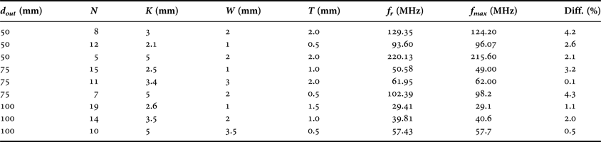
Table 1 shows a sample of our results for spirals with geometrical parameters d out, N, K, W, and T that satisfy conditions (12) and (13). The rightmost column shows the difference between f r and f max that is less than 4% for all cases.
f r and f max of different spiral dimensions.
Next we examine, if the Q-factor of a spiral has also a global maximum, Q Gmax, with respect to W. The proximity effect was considered because of its effect on changing width and spacing. By including the factor R p/R o, (11) can be written as:
 $$\eqalign{&Q_{max}= \cr & \quad \displaystyle{{\pi f_{max} \mu _o N^2 \left({\displaystyle{{d_{in}+d_{out} } \over 2}} \right)c_1 \left[{\ln \left({\displaystyle{{c_2 } \over \alpha }} \right)\, +c_3 \alpha+c_4 \alpha ^2 } \right]} \over {\displaystyle{{\ell _{tot} } \over {4\sqrt {WT} }}\sqrt {\pi \mu _o \rho f_{max} } \left({1+\displaystyle{{R_P } \over {R_o }}} \right)+31200\left({\displaystyle{{f_{max} } \over c}} \right)^4 \left({\sum\limits_{i=1}^N {d_i ^2 } } \right)^2 }}.}$$
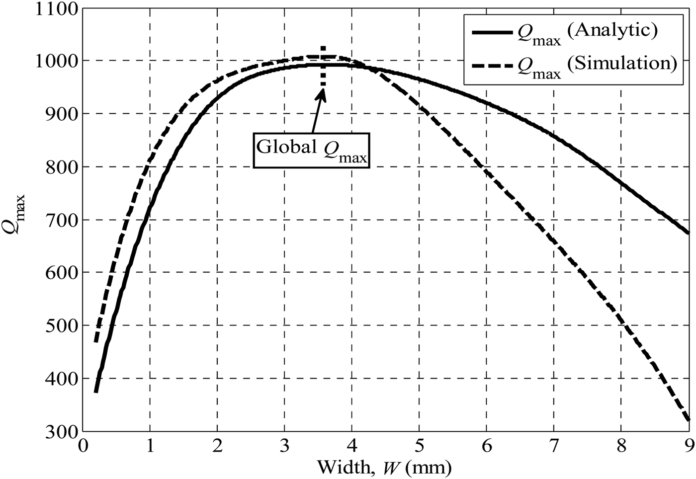
The standard calculus cannot be used to derive the global maximum analytically due to the complexity of (14). Nevertheless, Q Gmax can be calculated numerically by plotting Q max using (14) and observing if a global maximum exists. For example, a spiral with parameters N = 5, K = W + S = 10.2 mm, T = 0.5 mm, and d out = 100 mm is examined. The maximum Q-factor Q max is calculated analytically using (14) for W varying from 0.2 to 9 mm while keeping the distance between the centers of adjacent turns (K) of the spiral constant at 10.2 mm. Figure 5 shows the plots of Q max versus W and compares the analytical calculations with simulations. Figure 5 also illustrates clearly that a global Q Gmax occurs at W = 3.6 mm, in both the analytical and simulation results. This indicates that the spiral designed with a width of 3.6 mm will be globally optimum and have maximum efficiency for: N = 5, T = 0.5 mm and d out = 100 mm and K = 10.2 mm. The existence of the global maximum can be explained with reference to (6). The ohmic resistance of the spiral is inversely proportional to  $\sqrt W $ and it decreases as the width of the spiral is increased. However, if the width is increased while keeping K constant, the spacing between the turns decreases thereby increasing the proximity effect factor R p/R o. Hence, R p/R o sets a limit on the minimum value that the ohmic resistance can attain. The width corresponding to the minimum resistance is its optimum value, and when this happens Q max can attain its global maximum. It is important to note that in WPT via SCMR, the Q-factors of the resonators are very high due to the high inductance and low electrical resistance of the resonators. This has been validated by simulations and measurements in [Reference Mazlouman, Mahanfar and Kaminska5–Reference Karalis, Joannopoulos and Soljacic8]. This is the advantage of SCMR over other WPT methods. Similarly, the Q-factors shown in Fig. 5 are high, and in agreement with previous work on WPT via SCMR.
The local and global Q max.
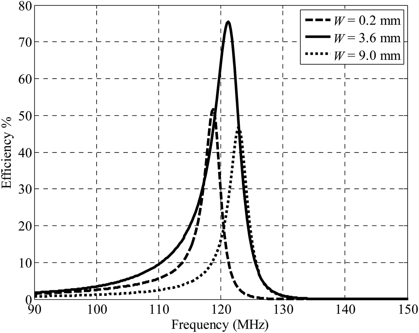
In order to verify the existence of global maximum Q-factor, Q Gmax, we designed SCMR systems that utilized the spiral parameters: N = 5, K = 10.2 mm, T = 0.5 mm, d out = 100 mm, and W = 0.2, 3.6, and 9 mm. The distance between TX and RX resonators was set to l 2 = 150 mm. The efficiency versus frequency plot for each of these designs is shown in Fig. 6, which illustrates that the SCMR system with the highest efficiency is the one that uses a spiral with W = 3.6 mm. The result of Fig. 6 confirms the observation from our previous discussion and results of Fig. 5.
The efficiency of the SCMR system for W=0.2, 3.6, and 9.0 mm
Based on the results, we can propose a process of designing spirals for globally optimal SCMR systems with maximum efficiency as follows: (1) pick desired frequency, f o, for WPT; (2) design spiral using (10) and satisfying S > 10W to exhibit maximum Q-factor at f o; (3) use (14) to find the optimum cross-sectional width of a spiral, W; (4) model SCMR system with the designed spirals (see Fig. 1) in simulation software using optimal W; (5) fine tune performance of SCMR design and f max in simulation software (e.g. by making minor adjustment in K).
Table 2 compares the parameters and efficiencies achieved in some papers with the result that we achieved in the work. The parameters of the work done in this paper are shown in cases I, II, and III, respectively. In this paper, the efficiency values is maximum at w = 3.6 mm, which is at the Q max as described in (14).
Comparison of different system SCMR parameters.
IV. CONCLUSIONS
This paper analytically examines the optimal design of SCMR systems that use spiral resonators. Specifically, a methodology, which guarantees globally optimal spiral-based SCMR systems, has been derived and verified.
ACKNOWLEDGEMENT
This work was supported by the National Science Foundation under Grants ECCS 1307984 and 1307762, the Army Research Office under Grant W911NF-13-1-0149 and the Dissertation Year Fellowship provided by Florida International University. The authors of this paper would like to thank the Air Force Office of Scientific Research for their support of this work through ARO grant W911NF-13-1-0149.
 Olutola Jonah received the B.Sc. and M.Sc. Degrees in electrical engineering from Obafemi Awolowo University, Ile-Ife, Nigeria, in 2000 and 2008, respectively. He also received his Ph. D. degree Electrical Engineering from Florida International University, Miami. His research interests include electromagnetic wave propagation in non-homogenous interfaces, antennas and RF circuits.
Arvind Merwaday is a doctoral student in Electrical Engineering at Florida International University, Miami, FL, USA. His research interest includes efficient wireless power transfer using SCMR method. He received B.E. degree from B.M.S. College of Engineering, Bengaluru, India, in 2008. He joined Cypress Semiconductors India Pvt. Limited, Bengaluru, after graduation for 3 years as Applications Engineer.
Stavros V. Georgakopoulos received the Diploma in electrical engineering from the University of Patras, Patras, Greece, in June 1996, M.S. degree in electrical engineering, and the Ph. D. degree in electrical engineering both from Arizona State University (ASU), Tempe, in 1998, and 2001, respectively. From 2001-2007 he held a position as Principal Engineer at the Research and Development Department of SV Microwave, Inc., where he worked on the design of high reliability passive microwave components, thin-film circuits, high performance interconnects and calibration standards. Since 2007, he has been with the Department of Electrical and Computer Engineering, Florida International University, Miami, where he is now Assistant Professor. He is an Associate Editor of the IEEE Transactions on Antennas and Propagation. His current research interests relate to wireless powering of portable, wearable and implantable devices, applied electromagnetics, novel antennas, and wireless sensors.
 Manos M. Tentzeris received the Diploma degree in electrical and computer engineering (magna cum laude) from the National Technical University of Athens, Athens, Greece, and the M.S. and Ph.D. degrees in electrical engineering and computer science from The University of Michigan at Ann Arbor.
He is currently a Professor with School of Electrical and Computer Engineering, Georgia Institute of Technology, Atlanta. He has helped develop academic programs in highly integrated/multilayer packaging for RF and wireless applications using ceramic and organic flexible materials, paper-based RFIDs and sensors, biosensors, wearable electronics, inkjet-printed electronics, “Green” electronics and power scavenging, nanotechnology applications in RF, microwave microelectromechanical systems (MEMs), system-on-package (SOP)-integrated (ultra-wideband (UWB), multiband, millimeter wave, conformal) antennas and adaptive numerical electromagnetic (FDTD, multiresolution algorithms). He heads the ATHENA research group (20 researchers). He is currently the head of the Electromagnetics Technical Interest Group, School of Electrical and Computer Engineering, Georgia Institute of Technology. From 2006 to 2010, he was the Georgia Electronic Design Center Associate Director for RFID/sensors research. From 2003 to 2006, he was the Georgia Institute of Technology National Science Foundation (NSF) Packaging Research Center Associate Director for RF Research and the RF Alliance Leader. During the summer of 2002, he was a Visiting Professor with the Technical University of Munich, Munich, Germany. During the summer of 2009, he was a Visiting Professor with GTRI-Ireland, Athlone, Ireland. In the summer of 2010, he was a Visiting Professor with LAAS-CNRS, Toulouse, France. He has authored or coauthored over 420 papers in refereed journals and conference proceedings, five books, and 19 book chapters. He is an Associate Editor for the International Journal on Antennas and Propagation.
Dr. Tentzeris was the Technical Program Committee (TPC) chair for the 2008 IEEE Microwave Theory and Techniques Society (IEEE MTT-S) International Microwave Symposium (IMS) and the chair of the 2005 IEEE CEM-TD Workshop. He is the vice-chair of the RF Technical Committee (TC16), IEEE CPMT Society. He is the founder and chair of the RFID Technical Committee (TC24), IEEE MTT-S. He is the secretary/treasurer of the IEEE C-RFID. He is a member of URSI-Commission D and the MTT-15 committee. He is an Associate Member of the European Microwave Association (EuMA). He is a Fellow of the Electromagnetic Academy. He is a member of the Technical Chamber of Greece. He is an IEEEMTT-S DistinguishedMicrowave Lecturers (2010–2012). He was an associate editor for the IEEE TRANSACTIONS ON MICROWAVE THEORY AND TECHNIQUES. He is an associate editor for the IEEE TRANSACTIONS ON ADVANCED PACKAGING. He has given over 100 invited talks to various universities and companies all over the world. He was the recipient/corecipient of the 2012 FiDiPro Professorship in Finland, the 2010 IEEE Antennas and Propagation Society Piergiorgio L. E. Uslenghi Letters Prize Paper Award, the 2011 International Workshop on Structural Health Monitoring Best Student Paper Award, the 2010 Georgia Institute of Technology Senior Faculty Outstanding Undergraduate Research Mentor Award, the 2009 IEEE TRANSACTIONS ON COMPONENTS AND PACKAGING TECHNOLOGIES Best Paper Award, the 2009 E. T. S. Walton Award of the Irish Science Foundation, the 2007 IEEE Antennas and Propagation Society (AP-S) Symposium Best Student Paper Award, the 2007 IEEE MTT-S IMS Third Best Student Paper Award, the 2007 ISAP 2007 Poster Presentation Award, the 2006 IEEE MTT-S Outstanding Young Engineer Award, the 2006 Asian–Pacific Microwave Conference Award, the 2004 IEEE TRANSACTIONS ON ADVANCED PACKAGING Commendable Paper Award, the 2003 NASA Godfrey “Art” Anzic Collaborative Distinguished Publication Award, the 2003 IBC International Educator of the Year Award, the 2003 IEEE CPMT Outstanding Young Engineer Award, the 2002 International Conference on Microwave and Millimeter-Wave Technology Best Paper Award, the 2002 Georgia Institute of Technology–Electrical and Computer Engineering Outstanding Junior Faculty Award, the 2001 ACES Conference Best Paper Award, the 2000 National Science Foundation (NSF) CAREER Award, and the 1997 Best Paper Award of the International Hybrid Microelectronics and Packaging Society.