I. INTRODUCTION
Kevlar ® fabrics have historically been used for protective systems to make use of their exceptional axial specific strengths. Recent developments in flexible protective textile composite systems have shown increased energy dissipation upon impact through incorporation of nanosized particulates.Reference Kalman, Merrill, Wagner and Wetzel1–Reference Decker, Halbach, Nam, Wagner and Wetzel3 From these studies, a primary source of improvement appeared to be a particle-fiber interaction mechanism. Upon impact, particles were embedded into adjacent fiber surfaces and restricted the ability of the fabric elements to move out of the way of the impactor. The extent of embedding is highly dependent on the local material properties of the Kevlar monofilaments and on the size, shape, and properties of the particles.
The nanosized particulates used in textile composite systems impart contact sizes on the fiber surface within the nano- to micrometer regime. In this work, nanoindentation techniques based on atomic force microscopy (AFM) and instrumented indentation were performed to study small-scale contact on Kevlar fibers. Probes with sizes ranging from nanometers to micrometers were used to determine mechanical properties (e.g., elastic modulus, E) and deformation with respect to radial position, contact size, and orientation.
A. Kevlar microstructure and bulk material properties
Kevlar fibers show distinctive microfibril orientation and core-shell structure (Fig. 1), where the near-surface region of the fiber shows a higher degree of crystalline block orientation relative to the fiber interior.Reference Riekel, Garcia Gutierrez, Gourrier and Roth4–Reference Panar, Avakian, Blume, Gardner, Gierke and Yang7 Kevlar 49, in particular, has received extensive morphology characterization with reported microfibril diameters of 100–200 nmReference Li, McGhie and Tan6, Reference Rao, Waddon and Farris8–Reference Lee, Barton and Schultz10 connected through a network of hydrogen bonds and Van der Waals forces. The thickness of the Kevlar 49 shell has been measured by AFM to range from 100 to 1000 nm.Reference Li, McGhie and Tan6 Similar measurements of Kevlar KM2 were not available in the literature.
Schematic of the Kevlar 49 morphology presented in the literature (after Panar et al.,Reference Panar, Avakian, Blume, Gardner, Gierke and Yang7). The inset shows the microfibrillar structure of a Kevlar 49 fiber as observed in the feedback phase signal of contact resonance AFM, where the scan angle was almost perpendicular to the fiber; the diagonally oriented features are a consequence of microtome slicing.

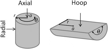
In prior studies, “bulk,” or volume-averaged Kevlar fiber properties have been measured using methods including microtensile testing and axial and diametrical microcompression tests. As a direct result of the high degree of orientation, the fibers possess superior properties in the axial (a) direction compared with the radial (r) (also referred to as “transverse”) or hoop (θ) directions,Reference Cheng, Chen and Weerasooriya11–Reference Tsai and Daniel18 and are commonly assumed to be transversely isotropic with the r-θ plane as the plane of isotropy. For example, the axial modulus, Eaa, was shown to be 1–2 orders of magnitude greater than the radial modulus, Err. Additionally, Eaa was found to be greater in tension (Eaa, tens.) than compression (Eaa, comp.) (Eaa, comp./Eaa, tens. ≈ 0.6) due to nonlinear kink band deformation and buckling failure at very small compressive strains (e.g., ∼0.5% for Kevlar 49).Reference Deteresa, Allen, Farris and Porter12, Reference Leal, Deitzel and Gillespie14, Reference Leal, Deitzel and Gillespie15 These studies ignored heterogeneities in the radial direction that might be due to the previously reported core-shell, microfibrillar microstructure and associated property differences or gradients. AFM techniques employed herein, with contact sizes on the order of a single microfibril diameter, allow for examination of the extent of fiber property variations with radial position. Instrumented indentation can subsequently be used to establish a critical contact size above which indents no longer show sensitivity to microfibril heterogeneity (i.e., the fiber effectively responds “homogeneously”), thus enabling the evaluation of local material properties.
B. Indentation of a transversely isotropic single fiber
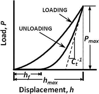
Indentation moduli can be directly determined by an indentation experiment, with most nanoindentation data analyzed using the Oliver-Pharr (O-P) method.Reference Oliver and Pharr19 In our prior work, modifications were developed that enable the use of the O-P method for measuring indentation modulus, M, on the curved surface of a single fiber that exhibits additional compliance due to the finite fiber dimensions.Reference McAllister, Gillespie and VanLandingham20 The total elastic contact compliance, Ct, is defined by the reciprocal of the slope of the unloading portion of a nanoindentation experimental load-displacement (P-h) curve (Fig. 2) fit at maximum indentation depth 
Traditional nanoindentation P-h curve identifying significant parameters. Reproduced from [20], with permission of Cambridge University Press.

The indentation modulus, M, can subsequently be determined with an appropriate correction for the added structural compliance and reduced indentation area induced by the finite fiber dimensions, Eq. (1).
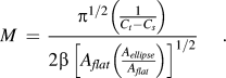
In Eq. (1), the indention probe (diamond, elastic modulus = 1141 GPa) is assumed to be infinitely stiff relative to the fiber, β is a constant dependent on probe shape (e.g., β = 1 for a conical tip), Aflat is the projected area of the indenter probe on a flat surface at contact depth hc, Aellipse is the projected area of the indenter probe at the same contact depth on a curved fiber surface, and Cs is the structural compliance associated with the fiber curvature, which can be determined from what Jakes et al.,Reference Jakes and Stone21, Reference Jakes, Frihart, Beecher, Moon and Stone22 termed a SYS compliance plot.
Indentation of an anisotropic sample results in a response that is a nontrivial function of the material’s directional properties.Reference Ebenstein and Wahl23–Reference Gindl, Gupta, Schoberl, Lichtenegger and Fratzl25 Delafargue and UlmReference Delafargue and Ulm26 developed explicit approximations for indentation moduli of transversely isotropic solids under conical contact conditions that adequately agree with prior numerical investigations.Reference Elliot27–Reference Swadener, Rho and Pharr34 The indentation moduli can be expressed as functions of Hooke’s Law stiffness coefficients (Cij) for indentation both parallel and normal to the plane of isotropy. In the cylindrical coordinate system, where a is the axial direction and r-θ is the plane of isotropy, the indentation moduli in the axial and radial (or hoop) directions (Ma and Mr) are given by Eqs. (2) and (3), respectively:
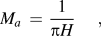
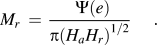
Ψ(e) is a measure of the anisotropy of the material and H, Ha and Hr = Hθ are functions of the material’s stiffness coefficients (not to be confused with indentation hardness, which is also typically represented by the variable H) given by:

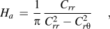

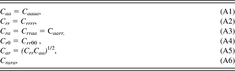
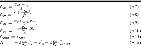
The definitions of the stiffness coefficients in terms of material properties are given in Appendix A.
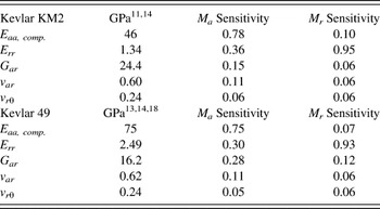
A sensitivity analysis of the Delafargue and Ulm indentation moduli to changes in the material properties of Kevlar 49 and Kevlar KM2 was conducted to indicate which local material properties most influence the indentation response, and thus can be best evaluated by the model through iterative back calculation from the measured indentation moduli. The published material properties (elastic modulus, Eii, shear modulus, Gij, etc.) summarized in Table IReference Cheng, Chen and Weerasooriya11, Reference Kawabata13, Reference Leal, Deitzel and Gillespie14, Reference Tsai and Daniel18 were substituted into the formulas for the stiffness coefficients (Cij), and the change in M was calculated whereas each material property was varied by ±50% of its published value with all other properties remaining constant. The “sensitivity,” also given in Table I, is the ratio of the percentage change in the calculated indentation moduli to the percentage change of the selected input material property. A value approaching 1 implies a high degree of sensitivity (for example, for KM2 a 50% increase in Eaa resulted in a 39% increase in Ma for a sensitivity value of 0.78). A value approaching zero implies no sensitivity where a change in the input property does not significantly affect the indention modulus (for example, for KM2 a 50% increase in Eaa resulted in only a 5% change in Mr for a sensitivity value of 0.10).
Sensitivity of indentation moduli to anisotropic material properties using the Delafargue and Ulm model.

The results in Table I show that the indentation moduli are most sensitive to the material property in the indentation direction (e.g., Ma is highly sensitive to Eaa). Thus, using the literature values for Gar, var, and vr θ for the two fibers and the Delafargue and Ulm model, Eaa and Err can be iteratively determined through a combination of axial and radial indentation. The combination of the Delafargue and Ulm model with the fiber curvature correction method thus accounts for the effects of the finite dimensions, curvature, and anisotropy of the fiber, each of which would otherwise violate the O-P method assumptions. For accurate evaluation of homogeneous properties, sufficient indentation contact sizes need to be achieved such that the indentation moduli are insensitive to the fiber heterogeneity. Instrumented indentation affords access to a wide range of contact sizes and was thus used herein to determine this threshold.
II. EXPERIMENTAL
AFM-based indentation was used to measure the material properties of fiber cross-sections at a resolution on the scale of the heterogeneous microstructure. A high frequency technique referred to as contact resonance AFM (CR-AFM) results in entirely elastic contact and the highest possible resolution. This method was used to characterize any radial property differences associated with the reported core-shell microstructure and associated length scales. Additionally, a quasistatic, elastic-plastic AFM indentation method using a sharp diamond-tipped, stainless steel cantilever was used to measure the influence of plastic deformation on the fiber radial property dependence. Relative to AFM-based methods, instrumented indentation affords access to a wider range of responses through increased control over tip geometry and force and displacement ranges. It was therefore used in this study to establish a minimum contact size above which the fiber response becomes constant (indicative of a local, homogeneous response and no longer sensitive to fiber heterogeneity), and from which the local, anisotropic Kevlar properties could be evaluated.
A. Materials and sample preparation
In this study, Kevlar 49 (diameter = 12.7 ± 0.7 μm, as measured optically from 5 measurements on each of over 40 fibers) and Kevlar KM2 (diameter = 12.4 ± 0.7 μm) single fibers were studied. Indentation on a single filament requires that the fiber be secured three-dimensionally to avoid any arbitrary deflections. Samples were prepared in two primary manners: (i) Securing a single, cylindrical filament for radial indentation, and (ii) preparing axial and hoop cross-section samples.
For radial indentation, a length of a cylindrical fiber sample was secured to a glass substrate by embedding the bottom of the fiber in a thin polymer coating. Both thermosetting (SC15 two-part epoxy) and thermoplastic films (a polystyrene (PS) softening technique described in detail elsewhere)Reference McAllister, Gillespie and VanLandingham20 were used. No variation of the indentation response was observed due to the different film materials. Generally, a single filament of either Kevlar 49 or KM2 was put in slight tension and draped over the glass substrate covered with the thin polymer layer (1–4 μm). The thermosetting polymer was allowed to gel to a tacky state prior to overlaying the fiber, and then provided sufficient time to cure and secure the fiber. In the thermoplastic softening technique, a second glass slide was placed over the fiber to ensure contact of the fiber over the entire length of the substrate (mass ∼0.117 g, creating a stress of less than 1% of Kevlar’s radial compressive strength),Reference Kawabata13 and the entire system was then sealed in a tetrahydrofuran (THF) vapor saturated environment for 15–20 min to soften the PS to an appropriate tackiness. Upon removal of the system from the enclosure, the PS dried, and the fiber was secured. Tensile tests of Kevlar filaments that had been immersed in THF for the same length of time did not exhibit changes in their material properties. A thin film was observed on the fiber surfaces, an artifact of the process that was extremely difficult to suppress. The indentation depths were typically greater than the film thickness, and the film was found to have a negligible influence on the measurement of fiber indentation modulus.
For axial and hoop indentation, fiber cross-sections were prepared. In previous research, polishing has been shown to damage the surface of Kevlar and disrupt the hydrogen bonded network, exposing the microstructure and reducing the local properties.Reference Languerand, Zhang, Murthy, Ramesh and Sansoz35, Reference Graham, McCague, Warren and Norton36 In one of these studies,Reference Graham, McCague, Warren and Norton36 microtome cross sectioning was found to cause far less damage to the surface. Thus, fiber axial and hoop cross-section samples were prepared by microtomy. Kevlar filaments were embedded in Epon EpoKwik epoxy, which was allowed to cure for 24 h, and microtomed at room temperature with an Ultracut E microtome (Leica Reichert-Jung, Buffalo Grove, IL) equipped with a diamond microtomy knife (Delaware Diamond Knives, Wilmington, DE). Cuts were made both parallel to and perpendicular to the fibers axial direction, revealing the r-θ (axial) and a-r (hoop) plane cross sections (Fig. 3). During the cutting process, care was taken to minimize damage to the exposed surface.
Prepared indentation planes.

B. Atomic force microscopy
1. Cross-section property mapping
a. Contact resonance AFM
CR-AFM is an acoustic techniqueReference Rabe, Janser and Arnold37 in which the probe-sample contact is modulated in the kilohertz to megahertz frequency range to detect the characteristic contact resonance frequencies of the cantilever. By using the dynamics of the system (clamped-spring coupled cantilever) and the mechanics of the probe-sample interaction, the measured contact resonances are converted into the local indentation modulus. An indentation modulus map can be generated based on the measured contact resonance frequency at every position in the scan. Either in mapping or point-mode measurements, CR-AFM has been used to reveal the mechanical response at the nanoscale of various materialsReference Stan and Cook38, Reference Stan, King and Cook39 and structures.Reference Stan, Ciobanu, Parthangal and Cook40–Reference Stan, Krylyuk, Davydov and Cook42 In the present work, the detection of the contact resonance frequency during regular contact-mode AFM scans with a MultiMode AFM (Bruker AXS, Santa Barbara, CA) was performed using a phase-locked-loop controller operated in constant-excitation mode (SPECS Zurich GmbH, Zurich, Switzerland). The AFM probe used for CR-AFM mapping was a PPP-SEIH integrated Si probe with a cantilever spring constant of 11.9 N/m and the first two free resonance frequencies of 124.5 kHz and 776.5 kHz, respectively. The applied constant force during scanning was about 225 nN. In converting the measured contact resonance frequency into indentation modulus, simple approximations have been considered to capture the local mechanics of the imaged Kevlar fibers: (i) The contact mechanics model used was the Hertz model, which assumes pure elastic deformation between the AFM probe and the sample and neglects the adhesion interaction; (ii) no correction was made for the nonflatness of the sample surfaceReference Stan and Cook38; and (iii) only the normal spring coupling was considered between the AFM probe and the sample with no correction for possible lateral spring coupling.Reference Stan and Cook38 The purpose of these simplified approximations was to provide an easy and direct analysis of the CR-AFM signal but still meaningful for the present investigation. Nanoscale topographic features can induce inaccuracies in the elastic modulus mapping by CR-AFM when their dimensions are between the established contact radius and the radius of the AFM probe. By neglecting the lateral coupling in conversion of the measured flexural contact resonance frequency into the elastic modulus of rough surfaces, errors up to 20% could be generated.Reference Stan and Cook38 To consider such contributions from the lateral coupling caused by roughness, it is necessary to do a self-consistent correlation between the contact resonance frequency map (as measured by CR-AFM) and its corresponding real topography (free of AFM probe convolution).Reference Stan and Cook38 In the present work, simple contact geometry between a spherical tip and a flat surface was appropriate in converting the determined stiffness into indentation modulus, based on the statistical results coming mostly from the measurements over flat areas of the investigated samples. The CR-AFM measurements on Kevlar fibers were calibrated with respect to the embedding epoxy matrix with a measured instrumented indentation modulus of 4.2 ± 0.2 GPa. Because CR-AFM results in entirely elastic contact and the highest possible resolution, it was used herein to detect the presence of any stiffness variations across a single cross-section.
b. Quasistatic AFM indentation
The AFM can also be run in “force mode” to indent the sample and generate elastic-plastic contact sizes greater than those of CR-AFM but still of the order of a Kevlar microfibril diameter, and much smaller compared with an instrumented indenter. The results of this technique were compared with those of the elastic CR-AFM measurements to examine the influence of plastic deformation on the heterogeneous fiber response. This AFM indentation technique requires a few additional computational stepsReference VanLandingham, McKnight, Palmese, Eduljee, Gillespie and McCullough43 to acquire a traditional P-h curve and enable analysis using traditional methods (e.g., O-P). Due to a number of experimental challenges, AFM indentation has primarily been used for relative material property measurements,Reference VanLandingham, Dagastine, Eduljee, McCullough and Gillespie44–Reference Bischel, VanLandingham, Eduljee, Gillespie and Schultz50 which is an appropriate method for detecting property gradients across a fiber. Thus, relative modulus measurements were made on the microtomed Kevlar cross-sections using a Dimension 3100 AFM (Bruker AXS, Santa Barbara, CA) equipped with a diamond tipped, stainless steel cantilever (spring constant, k = 268 N/m). For each cross-section (Kevlar 49 and KM2, axial and hoop), 100 indentation measurements were made using a force of ∼ 6 μN with a lateral spacing of approximately 200 nm between indents. The residual impressions were subsequently imaged in tapping mode. By measuring the maximum indentation displacement (hmax) of the cantilever and/or the area of the plastic impression, relative modulus values were determined over the fiber cross-section. Subsequently, absolute indentation modulus values were calculated using the epoxy matrix as a reference. Assuming an ideal conical probe:
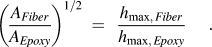
Combining Eq. (7) with the Oliver-Pharr indent modulus-compliance relationship, 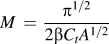 , gives the relative indentation modulus relationship:

2. Fiber topography
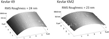
The Dimension 3100 AFM (Bruker AXS, Santa Barbara, CA) was also utilized to image the topography of fiber samples in tapping mode with a single beam silicon cantilever (TESP) probe. The resulting images (examples of the radial orientation are shown in Fig. 4) were used to measure the surface roughness of the Kevlar samples using ten 5 μm × 5 μm images over five fibers for each fiber type in the radial orientation. Root-mean-square roughness (rRMS) values for each sample are averages of ten measurements taken after the images were subjected to a 2nd order plane-fit procedure to remove the overall fiber curvature, leaving surface details essentially unaltered. The roughness values, rRMS, of the microtomed cross-sections were less than that of the unaltered fiber surfaces in the cases studied.
Representative AFM images of Kevlar 49 (left) and Kevlar KM2 (right) as-received fiber surfaces.

In prior research,Reference Tai, Ming, Suresh, Palazoglu and Ortiz51 a threshold indentation depth, h*, was found such that Oliver-Pharr indent measurements of depths h > h* were unaffected by surface roughness. This threshold depth for a Berkovich probe is given approximately by h* > 5rRMS. The relative bluntness of the rounded cones makes them more sensitive to roughness than the sharper Berkovich probe, but this estimate provides a reasonable value for h* of ∼ 115 nm for all tips used in this study. This value is at the lower end of the instrumented indentation depth range used, such that the data analyzed herein should not have significant roughness effects. Additional surface effects (e.g., film) observed at depths less than 100 nm were also limited by indenting beyond h*.
C. Instrumented indentation
AFM indentation and CR-AFM techniques probe the fiber properties at the lowest achievable contact areas, which are of the order of the fiber microstructure, such that the measured micromechanical response is more likely to be correlated to the fiber microstructure. Instrumented indentation affords access to a larger range of contact sizes and was thus used to examine the effects of contact size as well as to establish an area contact size beyond which measurements were insensitive to the microstructure (i.e., homogeneous behavior). To establish this effective contact area, instrumented indentation measurements of Kevlar 49 and Kevlar KM2 fibers were conducted using a Nanoindenter XP (Agilent Technologies, Santa Clara, CA) with the Continuous Stiffness Method (CSM) technique, which enables the continuous measurement of material properties with indentation depth.52 A target loading strain rate of 0.05 s−1 (variable load rate), unloading rate equal to the maximum loading rate, no hold period, an oscillation frequency of 45 Hz, and a target oscillation amplitude of 2 nm were used. Indentation modulus values were determined using the Oliver-Pharr unloading analysis method. Berkovich, 1 μm radius, 90° cone, and 3 μm radius, 90° cone diamond probes were calibrated using the standard CSM techniqueReference Oliver and Pharr19 and used for all subsequent measurements. Each tip was used to make indentations to depths of 100 nm, 200 nm, 300 nm, 400 nm, and 500 nm in three different fiber orientations: (i) At the center of the axial fiber plane (a) (axial at r = 0); (ii) at the center of the hoop fiber plane (θ) (hoop at r = 0); and (iii) radially, normal to the as-received fiber surface (r). Each axial indent was made on a separate filament, whereas those made in the hoop direction were made at most in sets of two per filament and separated by at least 50 μm, and the measurements in the radial direction were in-line on a single filament and separated by 25 μm. The Delafargue and Ulm model was subsequently used to interpret the homogeneous indentation measurements.
III. RESULTS AND DISCUSSION
A. Probing the heterogeneous morphology of Kevlar®
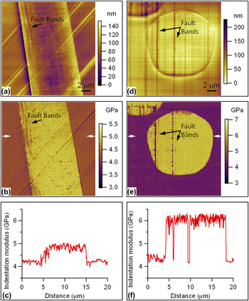
High-resolution property maps of Kevlar 49, produced using the CR-AFM technique, are given in Fig. 5. As shown in this figure, the modulus of the fiber was greater than the surrounding epoxy and greater in the axial plane. Occasionally, as can be seen in both the topography and indentation modulus maps in Figs. 5(a) and 5(b), Figs. 5(d) and 5(e), fault bands (indicated by the black arrows) had developed. They are not part of a core-shell, microfibril morphology, but rather the microfibrillar structure was perturbed during microtoming. Along these topographical features associated with microtomy damage, a reduction in the indentation modulus [refer to Figs. 5(b) and 5(c), Figs. 5(e) and 5(f)] can be observed in comparison with the rest of the fiber. Excluding these sample preparation-related features, no variation in the modulus of Kevlar 49 was observed within the fiber cross-sections with respect to radial position in either the hoop or axial planes. These observations indicate that the mechanical response of Kevlar 49 is insensitive to its radial location (no core-shell property distinction) and dependent only on the plane of indentation, consistent with transverse isotropy.
Kevlar 49 hoop (left) and axial (right) cross-sections with topography images (a) and (d) from contact-mode AFM, indentation modulus maps (b) and (e) from CR-AFM, and indentation modulus profiles (c) and (f) at the positions indicated in (b) and (e) by the white arrows, respectively. The black arrows indicate “fault bands” from damage/topography changes associated with microtome slicing. (color online)

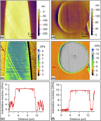
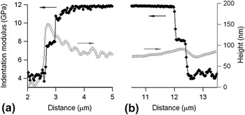
A representative set of CR-AFM property maps of Kevlar KM2 fibers are shown in Fig. 6 for both the hoop and axial planes. A shell region was distinctly identified as a reduced modulus region as wide as approximately 300–350 nm at the edges of the fiber sections [Figs. 6(b) and 6(e)]. Considering the mapping resolution in these images (∼30 nm/pixel) and the contact radius (within 10 nm), the observed decrease in the indentation modulus over the shell region is indeed an intrinsic property rather than an edge artifact. In the indentation modulus of the hoop section of the KM2 fiber [Fig. 6(b)], regions of apparent reduced modulus extend from the boundaries of the fiber toward the middle of the fiber. These features are the result of changes in the contact area during scanning along the occasional ripples and cutting grooves. Thus, the extent of the shell region is better delimited in the indentation modulus of the axial cross-section of the KM2 fiber [Fig. 6(e)]. From the line profiles [Figs. 6(c) and 6(f)] of the modulus maps, the decrease in the indentation modulus within the shell region was determined to be about 30% from the indentation modulus measured over the central part of the fiber. The measured variations in the topography and indentation modulus within the shell region are detailed in profiles taken across the fiber diameter, through the fiber axis parallel and perpendicular to the horizontal in Figs. 6(d) and 6(e). These section profiles are shown in Fig. 7. Their similarity illustrates the fiber symmetry. As can be seen from Fig. 7, the thickness of the coaxial shell around the axial cross-section of the measured KM2 fiber was about 300–350 nm, much larger than either the topographical waviness or probe-sample contact radius established during scanning.
Kevlar KM2 hoop (left) and axial (right) cross-sections with topography images (a) and (d) from contact-mode AFM, indentation modulus maps (b) and (e) from CR-AFM, and indentation modulus profiles (c) and (f) at the positions indicated in (b) and (e) by the red arrows, respectively. (color online)

Enlarged topography and indentation modulus section profiles of the edge of the KM2 fiber shown in Figs. 6(d) and 6(e): The profiles are taken through the fiber axis (a) parallel and (b) perpendicular to the image horizontal.

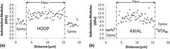
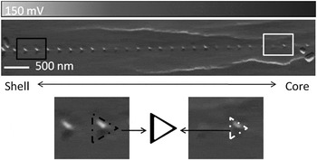
The probe-sample contact size is slightly increased by employing the elastic-plastic AFM indentation technique while maintaining a relatively high-mapping resolution and accessing the plastic deformation regime. Indentation modulus values across the fiber diameter in both the hoop and axial orientations of a single Kevlar 49 fiber agreed with the CR-AFM results, identifying no core-shell property distinction. The results taken over a single Kevlar KM2 fiber are given in Fig. 8. Although there are a few outlier points indicating an increased modulus in the outer fiber region, the results indicate a general decrease in modulus from the core to the outer shell region in the axial indentation orientation [Fig. 8(b)]. From post indentation imaging, the residual indent area for the Kevlar KM2 axial cross-section sample increased from the inner core region to the outer shell region (Fig. 9), indicative of a decrease in material hardness. This gradient observation (versus the distinct reduction observed with the elastic CR-AFM mapping) indicates a sensitivity of the modulus measurement to induced plastic deformation and/or the convolution of the core-shell properties due to the larger interaction volume. Moreover, the large amount of scatter observed in Fig. 8 may be, at least in part, due to sensitivity to elastic-plastic interaction with the local microfibrillar structure at these small contact sizes. The effect of indentation contact size is considered in detail in the Sec. III. B.
AFM indentation modulus over Kevlar KM2 (a) hoop and (b) axial cross-sections.

The amplitude error channel from a tapping mode scan of Kevlar KM2 AFM indents made over the axial cross-section. The bottom images highlight the reduction in residual indent area (i.e., harder/stiffer) as one moves from the shell to the core regions.

B. Establishing an effective contact size for homogeneous fiber property measurements
Instrumented indentation modulus measurements were made in the center of the fiber hoop (Mθ) and axial (Ma) planes of Kevlar 49 and Kevlar KM2 (and therefore primarily influenced by the fiber core properties of KM2) and analyzed using the technique described in Sec. I. B and Eq. (1) (modified O-P analysisReference Oliver and Pharr19), where modulus values were determined directly from the unloading curve for fiber indentation. Several different tip shapes were used, and moduli were measured as a function of contact area, which accounts for differences in probe shape more effectively than indentation depth. As the hoop and axial indentation measurements were made on essentially flat surfaces, the associated data only required a structural compliance correction to account for the softer surrounding epoxy matrix, similar to that performed by Jakes et al.Reference Jakes, Frihart, Beecher, Moon and Stone22 The data points in the subsequent hoop and axial modulus figures are averages of two to five tests (except for the 100-nm deep indent on the Kevlar 49 hoop sample with the Berkovich tip, where only one good measurement was made), and the error bars represent one estimated standard deviation.
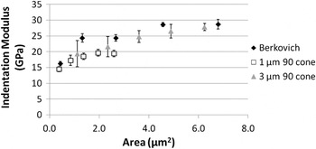
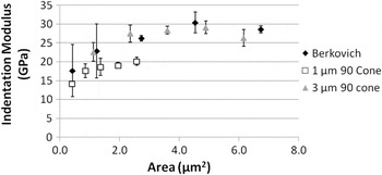
Kevlar 49 was shown to not exhibit any core-shell property distinction. Therefore, indentation in the center of the fiber planes should be indicative of the fiber local properties over the entire cross-section. Both Mθ (Fig. 10) and Ma (Fig. 11) of Kevlar 49 systematically increase with contact area, ultimately reaching a constant plateau value beyond contact sizes of ∼3 μm2 in the hoop plane and ∼4 μm2 in the axial plane. These values correspond to areas encompassing 10–20 axially oriented fibril diameters in the hoop plane and 100–500 fibril ends in the axial plane. The results suggest that initially individual microfibrils are being deformed and/or translated relative to surrounding microfibrils such that fibrillar interactions are important to the measured response. As contact sizes grow and more fibrils are encompassed by the indentation volume, the response transitions to one involving collective deformation of many fibrils such that the indent is no longer sensitive to individual microfibril interactions, but becomes representative of homogeneous behavior. Therefore, using only the plateau regions of Figs. 10 and 11, the homogeneous hoop and axial indentation moduli of Kevlar 49 were found to be Mθ , plateau = 11.0 ± 0.3 GPa and Ma, plateau = 27.9 ± 1 GPa, respectively.
Hoop indentation modulus @ r = 0, Mθ, of Kevlar 49 with respect to contact area.

Axial indentation modulus @ r = 0, Ma, of Kevlar 49 with respect to contact area.

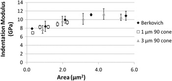
A similar increasing trend of indentation modulus in the hoop (Fig. 12) and axial (Fig. 13) planes was observed for Kevlar KM2. Similar contact sizes were required to reach the constant plateau measurements indicative of homogeneous behavior. A contact area of 3 μm2 is consistent with a contact radius of almost 1 μm, which is considerably larger than the measured shell thickness of 300–350 nm of the KM2 fiber. Therefore, independent measurement of the fiber shell properties cannot be achieved with these techniques. The largest contact sizes used corresponded to contact radius values of about 1.5 μm (again, made in the center of the fiber cross-sections) such that the measurements made should reflect the response of the KM2 fiber core. Thus, using the average plateau values, the Kevlar KM2 “effective” homogeneous hoop and axial indentation modulus values were determined to be Mθ , plateau = 9.8 ± 0.3 GPa and Ma, plateau = 28.6 ± 1.7 GPa, respectively.
Hoop indentation modulus @ r = 0, Mθ, of Kevlar KM2 with respect to contact area.

Axial indentation modulus @ r = 0, Ma, of Kevlar KM2 with respect to contact area.

Radial indentation data for the two fibers were subject to both the structural compliance and contact area corrections to account for the fiber curvature, as discussed elsewhere.Reference McAllister, Gillespie and VanLandingham20 The data points in the subsequent figures are averages of 4 to 10 tests (except for the “Run 3” 100-nm deep indents on the Kevlar KM2 sample using the Berkovich probe, where only two good measurements were made), and the error bars represent one estimated standard deviation.
For a transversely isotropic fiber, indentation in the radial orientation should agree with that in the hoop plane. The radial indentation modulus results for Kevlar 49, which thus far has shown consistency with transverse isotropy, are shown in Fig. 14. Mr did not exhibit any observable contact-area dependence and had an average value over all contact sizes of Mr = 11.2 ± 1.4 GPa. This value is approximately equal to the measured plateau value for Mθ, further supporting Kevlar 49’s consistency with transverse isotropy.
Radial indentation modulus, Mr, of Kevlar 49 with respect to contact area.

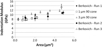
In contrast to Kevlar 49, Mr values increased for Kevlar KM2 fibers with increasing contact area (Fig. 15), and whether a plateau is reached at larger contact areas is difficult to ascertain. The radial indentation measurements were made at depths that fall in the range of, or at least partially include, the measured KM2 “shell” region, and indents of increased depth will become more sensitive to the fiber’s core properties. Therefore, the increase observed might be related to differences in the core-shell properties. However, in Fig. 12, the Mθ values at larger contact depths mainly fall between 8 GPa and 10 GPa, whereas in Fig. 15, Mr values at the largest contact depths (i.e., with the largest influence from the fiber core) repeatedly exceed 10 GPa. An “effective” Kevlar KM2 Mr value average over all contact areas was 9.6 ± 0.6 GPa, which is consistent with the plateau value for Mθ but may be a convolution of the radial core-shell indentation moduli.
Radial indentation modulus, Mr, of Kevlar KM2 with respect to contact area.

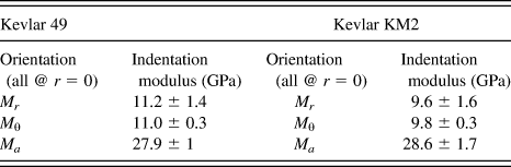
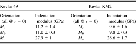
The homogeneous, local indentation moduli for each orientation of each fiber are summarized in Table II, and are subsequently used in Sec. III. C to evaluate the inherent, local fiber properties, Eaa and Err. It should be noted that the stiffening effect in Figs. 10–13 may in part be due to the rate sensitivity of local deformation of Kevlar fibers. The nature of the indentation experiment used in this study (constant “strain rate”), was such that loading rate increased with increased load, and unloading was performed at the maximum loading rate. Greater contact area corresponds to greater loads and, hence, greater unloading rates. Because prior Kevlar fiber studies have concluded that Kevlar is rate-insensitive within the elastic regime,Reference Cheng, Chen and Weerasooriya11 it is not expected that the range of rates imposed herein—less than one order of magnitude difference between the highest and lowest loading rates—would result in the 40%–50% change in elastic-plastic indentation modulus seen in Figs. 10–13. In any case, a study to examine the elastic-plastic rate sensitivity of these fibers using instrumented indentation is underway.
Homogeneous indentation moduli of Kevlar 49 and Kevlar KM2.
C. Determining the local properties of Kevlar
As stated previously, the indentation moduli reported above are convoluted responses of the local, anisotropic material properties. The local axial material modulus, Eaa, and radial material modulus, Err, can be calculated by iteratively applying the Delafargue and Ulm model to the homogeneous indentation moduli. The Delafargue and Ulm model was implemented for all the applicable data to be consistent, although it strictly only applies to conical indentation of a transversely isotropic material. A Berkovich probe (3-sided triangular pyramid) can be modeled as an ideal cone with a 70.3° half angle, and Vlassak and NixReference Vlassak and Nix31 calculated that the indentation modulus depends only slightly on the orientation of a probe with a triangular cross-section in the plane of indentation. Modifications for sphero-conical contact are being considered. However, indentation with the 3-μm radius cone at similar contact sizes to the Berkovich produces similar indentation moduli, which suggests that sphero-conical contact on an anisotropic material is not much different than conical contact. Whereas Kevlar 49 has shown consistency with transverse isotropy (radially independent properties and Mr ≈ Mθ are necessary but not sufficient conditions for transverse isotropy), results for Kevlar KM2 indicated a radial property dependence to which this analysis may be sensitive.
Eaa and Err were calculated for Kevlar 49 and Kevlar KM2 fibers using the iterative method described in Sec. I. B with the measured indentation moduli from Table II and the reported material properties from Table I as inputs in to the Delafargue and Ulm model (see Fig. 16).
The flow of the iterative procedure described in Sec. I. B to obtain the highlighted local material properties, Eaa and Err.

Initially, the indentation moduli themselves give only a 2.5–3:1 anisotropic ratio (very low compared with the 20–30:1 ratios given by the reported “bulk” measurements). Application of the Delafargue and Ulm model yields a 3.9:1 ratio for KM2 and a 3.1:1 ratio for Kevlar 49. Note that the model is dependent on the a-r plane shear modulus which has also been measured an order of magnitude lower, closer to ∼2 GPa,Reference Deteresa, Allen, Farris and Porter12, Reference Jones, Lara-Curzio, Kopper and Martin53 than the values used in this study. The use of Gar = 2 GPa increases the values of both Eaa and Err and gives anisotropy ratios, Eaa/Err, of 9–11. The experimental technique used to make the shear modulus measurements used herein was an advancement in the technique previously used in Deteresa et al.Reference Deteresa, Allen, Farris and Porter12 and Jones et al.,Reference Jones, Lara-Curzio, Kopper and Martin53 and we therefore believe the values utilized herein are more appropriate. Further, using Gar = 2 GPa yields Eaa values approaching measured axial tensile moduli of these fibers, which would be much too large for a compressive modulus measurement. In any case, these results indicate that the model results in only a slight increase in the measured fiber anisotropy.
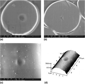
As shown in Table III, the iteratively determined local radial elastic moduli of Kevlar are approximately 2.5–4.5 times greater than the “bulk” literature values, whereas the local axial moduli of both Kevlar 49 and KM2 were measured significantly less than the “bulk” axial compressive moduli. These differences highlight a fundamental difference in the bulk and local loading conditions. Whereas the “bulk” axial and radial compressive moduli were determined from the elastic deformation of the entire fiber cross-sectional area under entirely elastic loading,Reference Cheng, Chen and Weerasooriya11–Reference Tsai and Daniel18 the “local” elastic moduli were determined from an unloading of a large number of fibrils contained in the contact area above the threshold level that had undergone significant plastic deformation during an elastic-plastic indentation. The residual impressions shown in Fig. 17 do not show evidence of microfibril rupture (no stray microfibrils about the indent zone), indicating that large-scale deformations and rotations of the fibrillar network must have occurred to account for the permanent deformation.
Various indent images of (a) a 500-nm deep, axial indent made with a 1-μm radius, 90° cone on KM2; (b) a 300-nm deep, axial indent made with a Berkovich probe on KM2; (c) and (d) 500-nm deep, radial indents made with a 1-μm radius, 90° cone on KM2 and imaged with SEM and AFM, respectively.

Comparison of the "bulk" compressive modulus values in the literature to the "local" values measured within this study for Kevlar 49 and Kevlar KM2. The error bars associated with the "local" moduli correlate to the standard deviation found in the corresponding indentation moduli.

Radial loading of the axially oriented fibril array by indentation at depths approximately 1–5 times greater than a fibril diameter potentially cause the fibrils to locally reorient, shear, and/or axially strain in tension at the contact angles imparted by the penetrating probe. Axial compression loading of the fibril array can result in debonding, buckling, and kink band formation that results in significant residual plastic deformation, such as collapse and rotation of fibrils transverse to this loading direction. The local indent unloading can therefore be expected to have altered contributions from the reoriented fibrillar network’s anisotropic properties. The net effect is that the “local” elastic unloading moduli from a plastically deformed indentation are greater than the “bulk” radial compression (i.e., a stiffening contribution from axial tensile and shear deformation) and less than the “bulk” axial compression modulus (i.e., a stiffness reduction from the transverse and shear loading of fibrils).
The Delafargue and Ulm model utilized herein to extract the fiber properties through indentation was developed based on the surface Green’s functions for an elastic half-space, with applicability within the elastic, small strain limit. It was not developed to account for deformations of the indented microstructure that lead to an alteration in the anisotropic response of the material. The results therefore indicate the significance of the deforming microfibrillar network of Kevlar fibers on their “local” response.
IV. CONCLUSIONS
In this study, nanoindentation techniques were used to measure the local, three-dimensional material properties of anisotropic fibers, specifically Kevlar 49 and Kevlar KM2. High-resolution CR-AFM modulus mapping was used to probe the fiber cross-section to observe any radial mechanical property dependence related to the reported core-shell microstructure. Whereas Kevlar 49 is known to exhibit a clear core-shell microstructure, no mechanical property distinction was observed, consistent with transverse isotropy. Kevlar KM2, however, exhibited a distinct shell property reduction within ∼300–350 nm of the outer fiber surface. Subjecting the KM2 fiber to elastic-plastic AFM indentation mapping resulted in the measurement of a radial property gradient (in place of distinct core and shell properties), suggesting indentation measurement sensitivity to induced plastic strain and/or increasing contact size.
Instrumented indentation was used to evaluate at what contact size the local properties of the fibers become insensitive to the microfibrillar structure. A constant modulus was measured at indent sizes encompassing greater than 10–20 microfibril diameters in the hoop and radial directions, and 100–500 microfibril ends in the axial direction. Above this contact size, the fibers appeared to exhibit homogeneous behavior (i.e., behavior independent of microstructure). Making use of a previously proposed data analysis method for indentation of a transversely isotropic medium, the local material axial, Eaa, and radial, Err, moduli were found. The ratios of these calculated moduli resulted in only slight improvements in agreement with the ratios anticipated from literature values for the bulk fiber compared with the ratios of the as-measured indentation moduli. A fundamental difference in the loading conditions of the “bulk” compressive literature measurements and the “local” measurements conducted herein resulted in local property measurements of a potentially significantly deformed fibrillar network. These nanoscale deformation mechanics of Kevlar fibers under local contact likely alter their overall anisotropic indentation response.
ACKNOWLEDGMENTS
QM and JWG gratefully acknowledge sponsorship by the Army Research Laboratory under cooperative agreement W911NF-06-2-0011. The views and conclusions contained in this paper should not be interpreted as representing the official policies, either expressed or implied, of the Army Research Laboratory or the U.S. Government. The U.S. Government is authorized to reproduce and distribute reprints for Government purposes not withstanding any copyright notation herein.
The authors wish to thank Dr. Gheorghe Stan for his efforts in obtaining the CR-AFM results. The authors would also like to thank Dr. Kenneth Strawhecker for useful discussions in data interpretation and Dr. Joseph Deitzel for help in formulating a proper mounting system.