I. INTRODUCTION
Currently, research on carbon nanotubes (CNTs) is of immense interest and growing very rapidly because of their outstanding mechanical, electrical, and thermal properties.Reference Iijima1–Reference Zhang, Fang, Zakhidov, Lee, Aliev, Williams, Atkinson and Baughman5 CNTs are chemically inert with extremely high strength (50 GPa) and high modulus (1 TPa).Reference Yu, Files, Arepalli and Ruoff6 CNTs are a very promising candidate for both textile and engineering applications, either in pure form or in composite with selected polymers.Reference Atkinson, Hawkins, Huynh, Skourtis, Dai, Zhang, Fang, Zakhidov, Lee, Aliev, Williams and Baughman7 Furthermore, CNTs have become a very attractive material for many industries such as aerospace, body armor, and sporting goods industries.
Exciting research efforts have been undertaken to synthesize long aligned CNTs.Reference Li, Xie, Qian, Chang, Zou, Zhou, Zhao and Wang8–Reference Christen, Puretzky, Cui, Belay, Fleming, Geohegan and Lowndes10 Currently, only a few groups have reported synthesis of high-quality long CNT arrays.Reference Ren, Huang, Xu, Wang, Bush, Siegal and Provencio3, Reference Li, Xie, Qian, Chang, Zou, Zhou, Zhao and Wang8–Reference Hata, Futaba, Mizuno, Namai, Yumura and Iijima11 Hata et al. have succeeded in growing 2.5 mm long aligned single-wall CNTs with a water-assisted catalytic vapor deposition (CVD) technique.Reference Hata, Futaba, Mizuno, Namai, Yumura and Iijima11 Recently, Chakrabarti synthesized long (7 mm) CNT array over a 12 h period by CVD.Reference Chakrabarti, Yoshikawa, Pan and Nakayama12 Twisting of long CNT arrays to make continuous yarns has become an important area of research for many industrial applications such as high-strength structural material and highly conducting fibers especially for high-frequency applications. The advantages of spinning threads from long CNT arrays are that longer nanotubes have larger surface area for load transfer. Also, larger-diameter threads can be spun from long CNTs, which would be beneficial in certain applications. However, synthesis of long and spinnable CNT arrays is complicated and spinning CNT threads from them a challenging task.
There are different approaches for producing nanotube threads or yarns such as coagulation spinning of single-wall CNTs and of MWNTs from a polymer solution,Reference Vigolo, Penicaud, Coulon, Sauder, Pailler, Journet, Bernier and Poulin13–Reference Miaudet, Badaire, Maugey, Derre, Pichot, Launois, Poulin and Zakri15 gas phase spinning of SWNTs and MWNTs from reaction furnace,Reference Motta, Li, Kinloch and Windle4, Reference Zhu, Xu, Wu, Wei, Vajtai and Ajayan16, Reference Li, Kinloch and Windle17 and spinning directly from aligned MWNTs grown on flat substrates.Reference Zhang, Jiang, Feng, Liu, Zhang, Kong, Zhang, Li and Fan18 All the aforementioned references are about spinning threads from short CNT arrays (less than 600 μm). Zhang et al. reported spinning of CNT threads from 650 μm long CNT arrays.Reference Zhang, Atkinson and Baughman19 Zhang et al. showed that fibers can be spun with comparable diameters ~4 μm from arrays of 300 to 650 μm in length.Reference Zhang, Jiang, Feng, Liu, Zhang, Kong, Zhang, Li and Fan18 The tensile strength of those spun fibers ranges from 0.32 to 0.85 GPa. Recently Zhang et al. reported making continuous MWNT fibers and yarns by dry spinning from a 1 mm long water-assisted CVD grown CNT forest.Reference Zhang, Zhu, Minus, Chae, Jagannathan, Wong, Kowalik, Roberson and Kumar20 They claimed that the maximum strength achieved by densifying the thread with ethanol was 0.35 GPa. However to our knowledge, there are no reports of successful spinning threads from CNT arrays longer than 1 mm.
In this paper, we report spinning of continuous CNT threads from longer CNT arrays of lengths ranging from 4 to 6 mm. The optimization of CVD parameters such as ethylene (C2H4) partial pressure, water (H2O)-to-ethylene (C2H4) ratio, and hydrogen (H2)-to-ethylene (C2H4) ratio for synthesis of long, spinnable CNT arrays is also discussed here.
II. EXPERIMENTAL PROCEDURE
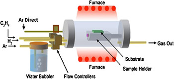
CVD is one of the most commercially practiced approaches for synthesis of carbon nanotubes (CNTs). The schematic diagram of the CVD system that was used to synthesize high-purity, well-aligned, and spinnable MWNT arrays is shown in Fig. 1. The CVD reactor consisted of a 3 in. quartz tube placed inside a high-temperature furnace. The computer-controlled CVD reactor was equipped with mass-flow controllers and moisture sensor to measure water concentration. Argon was used as a carrier gas along with hydrogen and a small amount of water vapor. Ethylene was used as carbon precursor gas. Low partial pressure of ethylene (~0.068) was used to obtain spinnable CNTs arrays. The reactor pressure was slightly higher than the atmospheric pressure. The CVD furnace used three-zone temperature control that maintained set temperatures accurately. The oxidized Si substrate was processed to form several multilayers. First, an Al2O3 (10 nm) buffer layer was formed on top of the oxidized Si substrate by e-beam deposition of pure Al, followed by its thermal oxidation. Next, an iron-based catalyst alloy (2 nm) layer was deposited over the Al2O3 by e-beam evaporation. All the experiments were conducted at 750 °C. Water vapor feed during CVD was generated by passing argon gas through a bubbler containing water. During the cooling step, the system was purged with a mixture of hydrogen and argon gases until the temperature reached 300 °C and finally with argon to ambient temperature.
CVD reactor used in this work.

The initial portion of the nanotube thread was produced by pulling the CNT array with a tweezers. Then the thread was attached to the spool of a spinning machine that was able to twist and spool the thread. The morphology and the microstructure of the CNT arrays and spun threads were studied by scanning electron microscopy (SEM) and high-resolution transmission electron microscopy (HRTEM). The micro-Raman spectra were collected in a backscattering geometry using Renishaw Raman spectrometer with 514 nm Ar ion laser excitation. The tensile properties of the threads at room temperature were determined by an Instron 5542 single-column test system with a gauge length of 7.2 mm and strain rate of 0.2 mm/min (2.8%/min).
III. RESULTS AND DISCUSSION
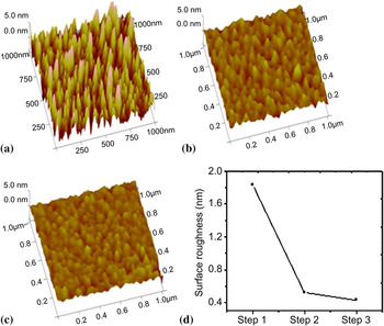
The surface morphology of the substrate used to grow CNTs was analyzed after different process steps by atomic force microscopy (AFM). The images observed from the surface of a 15 nm Al film and after plasma oxidation are shown in Figs. 2(a) and 2(b), respectively. Figure 2(c) shows AFM image of a 2 nm Fe alloy film deposited on top of the plasma oxidized Al layer. It reveals that the alloy catalyst nanoclusters are uniformly distributed on the substrate. The substrate preparation was conducted using e-beam deposition system. Figure 2(d) summarizes the AFM study and shows the variation of the root mean square (rms) surface roughness at different processing steps.
Results from the AFM study of the substrate before growth at different processing steps. (a) Morphology of the 15 nm Al layer. (b) Morphology of the Al layer after plasma oxidation. (c) AFM image of the Fe alloy catalyst particles. (d) Surface roughness variation for the processing steps illustrated in (a), (b), and (c).

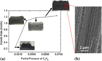
We found that low partial pressure of ethylene was a key factor for preventing formation of excess amorphous carbon during synthesis of spinnable CNT arrays, which helped avoiding excess amorphous carbon formation. Figure 3(a) shows the variation of CNT array height against partial pressure of the ethylene for 5 h growth. In general, the CNT growth rate increases with increasing partial pressure of ethylene. Significantly, however, higher partial pressure of ethylene dramatically increased the amorphous carbon deposition on the CNTs and decreased spinnability of the CNT array. We have observed that at very low ethylene partial pressure (0.048) the CNTs in the arrays were not aligned and less dense [see inset of Fig. 3(a)—CNT array grown at partial pressure 0.048 which is look like spaghetti], thereby preventing spinning. Study showed that an ethylene partial pressure of 0.068 was favorable for spinning. Figure 3(b), shows an SEM image of an “as-grown” CNT array with optimized partial pressure of ethylene.
(a) Plot of the CNT forest length as a function of the growth rate. Insets are micrographs showing the CNT forest produced at various partial pressure of ethylene. (b) SEM image of middle part of the CNT forest for ethylene partial pressure of 0.068.

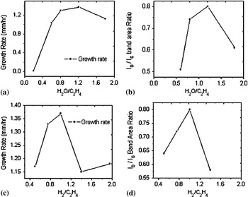
It was found that although optimizing the partial pressure of ethylene enabled CNT threads to be spun the thread uniformity and strength was unsatisfactory. Therefore, efforts were made to improve CVD growth conditions by varying water and hydrogen concentrations. The partial pressure of ethylene and the total gas flow rate were kept constant during the CVD for every experiment. Optimizing these parameters considerably increased CNT thread strength and quality. Chakrabarti observed that water and hydrogen play important roles in the growth of superlong aligned brushlike carbon nanotubes.Reference Chakrabarti, Yoshikawa, Pan and Nakayama12 Bronikowski claimed that high CNT growth rate can be achieved for an H2-to-C2H4 ratio of 0.25.Reference Bronikowski21 The variation of the water concentration was found to be a very effective tool for growing long CNT arrays. Figure 4(a) shows CNT growth rates as a function of H2O-to-C2H4 ratio. It was found that the highest spinnability of the CNT arrays was achieved for a H2O-to-C2H4 ratio of 1.2. It is obvious from these experiments that optimization of water concentration helped to increase growth rate of spinnable CNT arrays. At high temperature, water vapor acts as a weak oxidizer removing the amorphous carbon deposited on the catalyst particles as well as on CNTs. Figure 4(b) shows the Raman D-band to G-band area ratio of CNT arrays grown for different H2O-to-C2H4 ratios. The Raman D-band to G-band ratio initially increases with increasing water concentration. A maximum peak is observed at H2O-to-C2H4 ratio of 1.2, and then the ratio decreases with further increase of water. The existence of such a peak demonstrates that the balance between H2O and C2H4 is the most critical factor for good spinnability and high growth rate of CNTs arrays.
(a) Variation of CNT growth rate with the H2O-to-C2H4 ratio. (b) Raman D- to G-band area versus H2O-to-C2H4 ratio. (c) Variation of CNT growth rate with the H2-to-C2H4 ratio. (d) Raman D- to G-band area versus H2-to-C2H4 ratio.

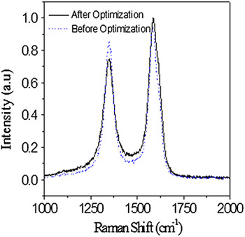
For further quality improvement of the CNT arrays we varied the ratio of hydrogen to ethylene. The hydrogen flow rate was changed from 40 to 195 sccm by keeping the partial pressure of ethylene and total flow rate constant. Figure 4(c) shows the variation of CNT growth rate with the H2-to-C2H4 ratio. Maximum growth rate was achieved for H2-to-C2H4 ratio of 0.08. Also Fig. 4(c) indicates that a slight increase in H2 flow rate (140 sccm) causes a significant decrease in the CNT growth rate. It is known that hydrogen affects the decomposition kinetics of ethylene at elevated temperatures. When the hydrogen fraction is high, the rate of C2H4 decomposition (C2H4 = 2C + 2H2) is low. Figure 4(d) reveals that the Raman D-band to G-band ratio of CNTs is highest (about 0.8) at the optimized flow rate of hydrogen gas. Figure 5 shows representative Raman spectra of CNT arrays before and after optimization and indicates the presence of D-band and G-band features around 1340 and 1575 cm−1, respectively. The purity of the CNTs is assessed on the basis of the ratio of the D-band to G-band peaks. The G-band is representative of the degree of graphitization associated with the nanotube growth, while the D-band indicates the presence of amorphous carbon, disorder, open end other defects in the tubes. The D-band to G-band ratio can be used as a rough measure of the carbon nanotube quality. From this viewpoint our CNT arrays revealed good quality because we used low partial pressure of ethylene. It was observed that the D-band to G-band ratio of Raman spectra decreases from 0.87 to 0.81 as a result of the optimization of the CVD parameters. This ratio is lower than the one reported by other groups producing spinnable MWNTs arrays.Reference Zheng, Zhang, Li, Chikkannanavar, Li, Zhao, Liao, Jia, Doorn, Peterson and Zhu22
Raman spectroscopy of a CNT array showing the D- and G-bands before (dashed line) and after (solid line) optimization.

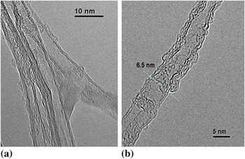
Figure 6(a) shows high-resolution transmission electron microscope (HRTEM) images of the optimized carbon nanotubes. As shown in this figure the nanotubes are mostly double walled. Their outer diameters are in the range of 9 to 12 nm. Figure 6(a) confirms that the nanotube walls are well graphitized with some amount of amorphous carbon on the sidewalls. The deposit of amorphous carbon is illustrated in Fig. 6(b).
HRTEM images of (a) CNT bundle and (b) individual CNT showing some amorphous carbon on the side walls.

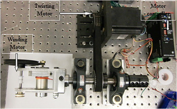
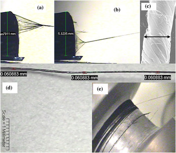
Optimized CNT arrays were spun into thread using in-house built spinning setup is displayed in Fig. 7. This tool has good control of the pulling and twisting speeds that is controlled by a computer-aided electrical motors. CNT threads were spun directly from the substrate at a pulling speed of 40 mm/min and a twisting rate of 250 min−1. Figures 8(a) and 8(b) show optical pictures taken during spinning of CNT threads from 5.3 mm long optimized CNT arrays. Uniform web of nanotubes was pulled and twisted into thread directly from the substrate as shown in Fig. 8(b). During the spinning of such long CNT arrays, a linear motion (up and down) of the triangle nanotube web forming the thread along the length of array was noticed. Figure 8(a) indicates that the starting position of spinning is the top part of CNT arrays and then the bundles shift toward the bottom of the CNT array [see Fig. 8(b)]. This motion back and forth continues during the whole spinning process. Also Figs. 8(a) and 8(b) illustrate that macroassemblies of CNTs, in the form of bundles both with and without cores, were easily formed during spinning of thread from the CNT array. This reveals that CNTs are tightly binding by van der Waals interactions. SEM image of the thread formed by twisted nanotube bundles indicates an average thread diameter of 70 μm as shown in Fig. 8(c). It was observed that CNT arrays of height and width of 5 and 2 mm, respectively, produced about threads of 60 to 80 μm in diameter. CNT arrays of lengths 300–600 μm similar widths produced CNT threads with diameters of 5 to 10 μm. Figure 8(d) shows an optical image of ~60 μm diameter CNT thread. A spool with about 5 m long coiled CNT thread is shown in Fig. 8(e). This thread was spun from a 5 mm long aligned CNT array.
Semiautomated spinning machine used in this study.

Images showing different stages in the formation of a carbon nanotube thread by spinning: (a) picture of the initial formation of the thread on top of the array; (b) thread formation at the bottom of the array; (c) SEM image of CNT thread with diameter ~70 μm; (d) microscopic image ~60 μm diameter thread; (e) 5 m long thread coiled on a spinning spool.

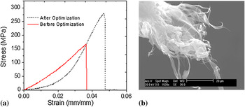
Figure 9(a) displays stress–strain curve for a spun thread from long CNT arrays before optimizing the CVD parameters (solid red line) and after optimization (dashed line). Our study shows that the mechanical properties of threads dramatically improve after optimization of the CVD growth. The maximum tensile strength values observed before and after optimization are 168 and 278 MPa, respectively. The corresponding Young’s moduli are 1.6 and 6.5 GPa, respectively. The maximum strength achieved for the yarns spun from long CNT arrays are comparable with those reported by other groups for yarns spun from short CNT arrays without any posttreatment.Reference Zhang, Atkinson and Baughman19 The failure mechanism of our CNT thread was studied using SEM as shown in Fig. 9(b), which suggests that the loose attachment between the CNTs in the threads is a factor limiting the tensile strength. We hope this can be improved by optimizing the spinning process.
(a) Stress–strain curve for CNT thread before and after optimization, solid and dashed lines respectively. (b) SEM image of the failure mode of CNT thread before optimization.

IV. SUMMARY
CNT threads have been synthesized using water-assisted CVD growth. Improved CNT quality, thread spinnability, and thread strength were achieved by optimizing water and hydrogen concentrations during CVD growth of the nanotube arrays. We successfully spun CNT thread from CNT arrays that were several millimeters long. CNT thread diameter was easily controlled from 15 to 80 μm as a result of the excellent drawing performance of the optimized CNT arrays. Future work is directed at improving thread properties by improving the quality of the CNT arrays and posttreatment of the threads.
ACKNOWLEDGMENTS
The authors wish to acknowledge Dr. Sergey Yarmolenko and Svetlana Fialkova from North Carolina A&T State University for providing the facilities to test the mechanical properties of the CNT threads. The authors are grateful to Mr. Doug Hurd for helping to set up the spinning machine. The financial support from the National Science Foundation through grants CMMI-0727250 and Dr. Shaochen Chen; CMS-0510823 and Dr. Shih-Chi Liu; Air Force for SBIR Contract No. FA8650-09-C-2908; NCA &T the Center for Advanced Material and Smart Structures and DURIP-Office of Naval Research are gratefully appreciated.