can be measured independently of any plastic deformation exhibited during loading through
 , where a(t) is the contact radius, h(t) is the displacement of the contact probe, and P
I. INTRODUCTION
As instrumented indentation experiments can be conducted to apply constant indentation depth while monitoring a decreasing load, as well as constant applied load while monitoring an increasing indentation depth, it is reasonable to expect that one can extract from such data properties such as the relaxation modulus and creep compliance. For example, in the case of load relaxation, ideally a step displacement  of the indenter probe is applied (where
 is the Heaviside function) and the resulting load P(t) is monitored. However, in practice it remains challenging to identify which relaxation properties can be obtained rigorously from such a facile experiment, and specifically how the relaxation modulus can be best extracted from the experimental data. Several previous useful approaches have been developed, and here we focus specifically on how one may obtain the relaxation modulus or creep compliance of the material when it is likely that plastic deformation of the material occurs concurrently with this time-dependent deformation.
For indentation by rigid axisymmetric punches on an elastic solid, GalinReference Galin1 derived the following relationReference Sneddon2:

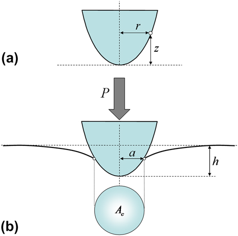
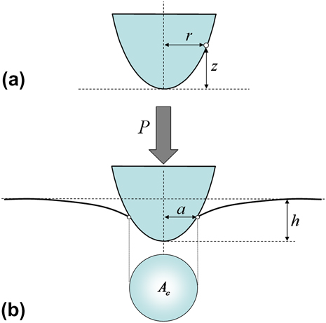
where z = Brn defines the geometric profile of the indenter probe (Fig. 1), B is the shape function of the indenter at unit radius, n ≥ 0 is the degree of the homogeneous function, Γ(x) is the Euler Gamma function, and M 0 can be termed the indentation elastic modulus. This indentation modulus M 0 provides a snapshot of the stiffness of the indented material. In the case of a linear elastic, isotropic half-space, M 0 relates to the elastic properties of the material as:

Parameters used to define (a) the geometry of the indenter probe; (b) the geometry of the contact problem during indentation.
where ν0 is the Poisson’s ratio and where E 0, K 0, and G 0 are the Young’s, bulk, and shear elastic moduli of the indented material, respectively.
We now consider a rigid punch of axisymmetric shape indenting an infinite half-space made of a nonaging linear viscoelastic material. The method of functional equationsReference Lee and Radok3 (or equivalently the s-multiplied Laplace or Carson transform) allows one to obtain the solution to a linear viscoelastic indentation problem in the Laplace domain from the linear elastic solution by replacing the elastic constants in the elastic solution with the Laplace transform of the time-dependent expressions of the elastic moduli multiplied by the Laplace parameter. (The method of functional equations is in fact restricted to problems for which the contact area between the indenter tip and the indented surface is monotonically increasing.Reference Vandamme and Ulm4) Applying this method to Eq. (1), one finds that, during an indentation relaxation experiment, the function M(t) defined as:

depends neither on the applied indentation depth h max nor on the geometry of the axisymmetric indenter. We hereafter term M(t) as the contact relaxation modulus of the indented material. This function verifies M(t = 0+) = M 0.
Similarly, we can also consider an indentation creep experiment in which a step load P(t) = P max (t) is applied via the indenter probe, and in which the displacement h(t) of this probe into the material surface is measured. Applying the method of functional equations to Eq. (1), one now finds that, during such an experiment, the function L(t) defined as:

depends neither on the applied load P max nor on the geometry of the axisymmetric indenter. We term L(t) the contact creep compliance of the indented material, which is also sometimes noted as J c(t).Reference Tweedie and Van Vliet5 This function verifies L(t = 0+) = 1 / M 0 and is linked to M(t) in the Laplace domain, akin to the well-known relation between the creep compliance and the relaxation function under uniaxial deformationReference Christensen6:
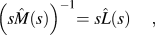
where s is the Laplace parameter, and  is the Laplace transform of f(t).
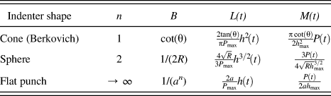
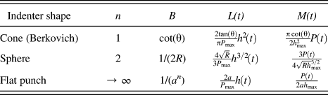
The contact creep compliance and contact relaxation modulus characterize the time-dependent response (to which we refer from hereafter collectively as the “creep” response) of the indented material. For a creep response which is linear with regard to the applied stress (to which we refer hereafter as “linear creep”), L(t) and M(t) are material properties. These properties depend neither on the geometry of the axisymmetric indenter nor on the maximum value of the control variable (P max for an indentation creep experiment; h max for an indentation relaxation experiment). Table I lists expressions of L(t) and M(t) for several common contact probe geometries. For other loading profiles judiciously chosen, there exist other simple relations which enable as well to link the measured penetration depth or load to material viscous properties.Reference Cheng and Yang7
Contact creep compliance L(t) and contact relaxation modulus M(t) for different axisymmetric indenter shapes: θ is the half-cone angle (respectively the equivalent half-cone angle in Berkovich indentation), R is the sphere radius and a is the flat cylinder punch radius.
Practically, however, the measurement of the indentation creep and relaxation functions is impeded by the time-independent and instantaneous plastic deformation (to which we refer from now simply as to the “plastic” deformation) of the material beneath the indenter. Such plastic deformation cannot be avoided below a sharp probe (e.g., below a Berkovich three-sided pyramidal probe) and often also occurs below spherical and flat punches. Plastic deformation results in an increase in indentation depth (at a given load) or in a decrease in load (at a given depth). As a consequence, Eq. (4) overestimates the contact creep compliance, and Eq. (3) underestimates the contact relaxation modulus. Consequently, as noted by Tweedie and Van Vliet,Reference Tweedie and Van Vliet5 when plastic phenomena occur, Eqs. (3) and (4) provide metrics of material response which are not material properties, as these parameters depend on the uncontrolled amount of plasticity exhibited during the experiment and therefore on both the loading profile and the indenter geometry. Except for materials of high creep compliance, for which the plastic deformation is negligible compared to the viscous deformation, and for which the relaxation modulus or the creep compliance of a material can be extracted with confidence using viscoelastic solutions,Reference Shimizu, Yanagimoto and Sakai8 neglect of preceding or concurrent plastic deformation generally leads to an erroneous estimation of the viscous properties of the material.
To overcome this limitation, several approaches were recently proposed. Oyen and Cook suggested that the total indentation depth can be divided among an elastic, a plastic, and a viscous contribution.Reference Oyen and Cook9–Reference Olesiak, Oyen and Ferguson12 This intuitive and effective model remains one-dimensional and does not solve the creep problem at the level of the material (which deforms by all three means concurrently). Implicitly evoking the material constitutive laws, Zhang et al.Reference Zhang, Zhang, Zeng and Shen13, Reference Zhang, Zhang, Zeng and Shen14 proposed the measurement of viscous parameters by means of loading–unloading–reloading cycles combined with the concept of “effective” indenter shape introduced by Pharr and Bolshakov.Reference Pharr and Bolshakov15 The “effective” indenter shape is unknown a priori, and thus the experimental implementation requires several iterations, making this method less appealing for routine yet quantitatively accurate indentation analysis. These authors also developed another procedure, based on an “effective” flat punch indenter, which is more straightforward to implement experimentally but is limited to indentation relaxation analysis.Reference Zhang, Zhang, Zeng, Shen and Wang16 Starting from the finite element analysis of indentation on plastic linear viscoelastic materials, Seltzer and MaiReference Seltzer and Mai17 proposed a procedure to separate the viscoelastic response from the plastic response; their procedure involves spherical indentations at different loads. Several authors studied indentation on elastoviscoplastic materials with finite element methodsReference Anand and Ames18, Reference Hartmann, Gibmeier and Scholtes19: some of them used finite element analysis to back-calculate the viscous parameters of such materials from indentation by designing inverse methods based on neural networksReference Tyulyukovskiy and Huber20 or on the minimization of objective functions.Reference Rauchs and Bardon21
Here, we propose a novel method for separation of the creep from the instantaneous plasticity responses of a viscoelastoplastic material under contact loading. This analytical approach is both reliable and practical for linking experimental load, displacement, and time data to the contact creep and relaxation functions of the material. Our analysis combines analytical proofs and numerical simulations of contact creep and relaxation experiments on nonaging viscoelastoplastic materials for which the time-dependent (or creep) response is considered linear as defined above. The analytical forms of the creep compliance and relaxation modulus are derived under the assumption that no further instantaneous plastic deformation occurs during the relaxation or creep phase. In the context of relaxation, this assumption is validated analytically and numerically. In the context of creep, this assumption is not validated numerically and contributes to a small error in the analytical derivation. Finally, based on experimental indentations on polystyrene using a sharp pyramidal probe, the application of the proposed method to nonlinear time-dependent behavior is discussed.
II. ACCOUNTING FOR PLASTICITY IN INDENTATION RELAXATION EXPERIMENTS
Let us first consider indentation relaxation experiments, for which the associated contact mechanics problem is relatively less complicated. Indeed, as we shall show, under the assumption of a time-independent Poisson’s ratio the contact area does not evolve over the relaxation phase. We focus on an indentation relaxation experiment on a viscoelastoplastic half-space for which the creep response is linear, and to which a Heaviside step indentation displacement h(t) = h max (t) is applied. We show subsequently that the plasticity that occurs during the instantaneous displacement loading can be separated from the time-dependent creep deformation during the relaxation phase, such that the measured force relaxation response P(t) can be directly linked to the indentation relaxation function M(t) by:

where M 0 is the instantaneous indentation modulus of the tested material and P(0+) = P max is the maximum force recorded in the relaxation experiment, immediately after application of the Heaviside displacement. Note that this solution requires assuming the time invariance of the Poisson’s ratio of the indented material. This proof is outlined below.
A. Analytical proof of rescaling formula for relaxation experiments
Let  ,
 ,
 , and
 be the stress, total strain, plastic strain, and displacement solution fields generated instantaneously by the Heaviside step indentation displacement (i.e., at t = 0+). The half-space behaves elastoplastically during the infinitely fast loading. We tentatively assume that no further plastic deformation occurs during the relaxation phase t > 0+. (This assumption will be verified later.) Separating the stress and strain tensors into their deviatoric (superscript d) and nondeviatoric or volumetric (superscript v) components, the creep behavior of the solid during the relaxation phase is governed by the hereditary integral functions:
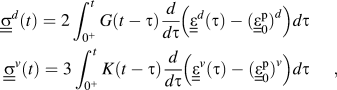
where G(t) is the shear relaxation modulus and K(t) is the bulk relaxation modulus of the indented half-space. We keep in mind that both G(t) and K(t) are monotonically decreasing functions. We restrict ourselves to a viscoelastoplastic half-space characterized by a time-invariant Poisson’s ratio ν, as frequently assumed in viscoelastic indentation analysis,Reference Johnson22 which implies:

The stresses, strains, and displacements must satisfy at all times the following field equations:
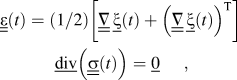
where  is the transpose of
 . The following boundary and frictionless contact conditions must also be satisfied at all times:
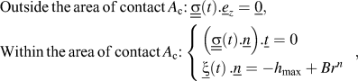
where  represent the outward unit normal and tangential vectors of the half-space. At t = 0+, the solution fields
 ,
 , and
 satisfy the field equations [Eq. (9)] and the boundary conditions [Eq. (10)], while the constitutive relations [Eq. (7)] are defined as:

where G(0) = G 0 and K(0) = K 0 are the elastic shear and bulk moduli of the indented half-space, respectively.
During the relaxation phase (t > 0+), for which the applied displacement is constant, we assume that the contact area between the indenter and the half-space is also constant. Using Eq. (8), the following displacement, stress, and strain fields are readily found to satisfy the set of governing Eqs. (7), (9), and (10):
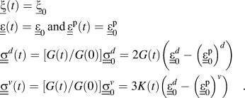
Moreover, since G(t) and K(t) are decreasing functions, the maximum stresses occur at t = 0+, which justifies a posteriori the assumption that no plasticity occurs after loading. Therefore, the fields shown in Eq. (12) are the solution of the relaxation indentation experiment in a viscoelastoplastic solid with time-invariant Poisson’s ratio, and the assumption of a time-invariant contact area between the indenter and the half-space over the relaxation phase is justified.
On this basis, we derive the force relaxation history P(t) for the viscoelastoplastic half-space:
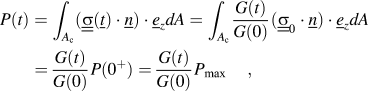
where P(0+) = P max is the maximum indentation force recorded immediately after the Heaviside displacement loading. Starting from the elastic relation  , one infers from a direct application of the method of functional equations that the viscous relaxation solution for the case of time-invariant Poisson’s ratio can be expressed in the Laplace domain and in the time domain asReference Lee and Radok3:

Finally, a combination of Eqs. (13) and (14) yields the relation of interest given in Eq. (6), which relates the indentation relaxation function M(t) to the load history P(t).
Strictly speaking, the analytical proof holds for a time-invariant Poisson’s ratio [see Eq. (8)]. This condition is not fulfilled for a material which creeps deviatorically but not volumetrically, for which the Poisson’s ratio ν(t) is time-dependent since:

Nevertheless, we note that, for an incompressible material with deviatoric creep, the Poisson’s ratio ν(t) = 1 / 2 is indeed time-invariant and Eq. (6) holds.
B. Numerical validation
To assess the validity of Eq. (6), we conducted numerical simulations of conical indentation relaxation for a viscoelastoplastic material via the finite element method.
1. Numerical implementation
Numerical simulations were carried out with ABAQUS (Dassault Systemes, Nanterre, France). The included half-cone angle was θ = 70.32o, which is the equivalent cone angle of the three-sided pyramidal Berkovich indenter.Reference Larsson, Giannakopoulos, Soderlund, Rowcliffe and Vestergaard23 The indentation proceeded from the top surface of the mesh and normal to the free surface of the material. An axisymmetric mesh refined in several steps around the indenter probe was used. The mesh consisted of 7630 nodes and of 7979 CAX4 (4-node bilinear) elements. The displacement of the indenter probe was imposed, and the load P(t) applied to the indenter was output from the numerical simulation. The density of the mesh was such that, during the relaxation phase, at least 40 elements contacted the indenter. Outside of the area of contact, the top surface of the sample was stress-free. Displacements in the direction of indentation were prevented at the bottom of the mesh, far from the indentation contact point. To evaluate the influence of such boundary effects on the simulations, the simulations were repeated with two sets of boundary conditions. In a first set, frictionless radial displacements of the bottom surface of the sample were allowed and the outer surface of the sample was stress-free. In a second set, both the bottom surface and the outer surface of the sample were fixed. For all simulations, the calculated output load changed by less than 0.5% according to these boundary conditions. To simulate an instantaneous loading, viscous properties were dismissed during the loading phase. As a result, the displacement history applied to the indenter corresponded to a Heaviside function.
Two instantaneous Poisson’s ratios were used in the simulations: ν0 = 0.499 to model an incompressible material and ν0 = 0.25 to model a compressible material. The viscous behavior of the indented material was modeled with the deviatoric Maxwell creep model, characterized by its viscosity η M. The duration of each simulated experiment was at least 15 times greater than the characteristic relaxation time of this simulated material η M/ E 0. The material was elastic perfectly plastic. The incompressible plastic flow was modeled with an associated von Mises plasticity model. The ratio of yield strength to Young’s modulus was σ y / E 0 = 10−3, which is a lower bound value for most materials.Reference Ashby24
We considered large displacements. At the material level, ABAQUS takes into account the coupling between creep and plasticity by using an implicit (backward Euler) integration scheme and a Newton Raphson scheme to solve the resulting nonlinear equations.
2. Results and discussion
Elastic properties in the form of the indentation modulus  and the maximal displacement h max were inputs to the numerical simulation, from which the resulting load history P(t) was determined. For the two instantaneous Poisson’s ratios considered, the maximum load obtained from the simulations was at least 19 times as small as would have been obtained if the material could not undergo plastic deformation. Therefore, the simulated indentations exhibited a significant amount of plasticity.
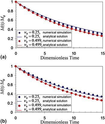
From Eq. (6), we calculated the normalized contact relaxation function M(t) / M 0 = P(t) / P max. The numerical relaxation function was then compared with a linear viscoelastic analytical solution for deviatoric Maxwell creep modelReference Vandamme and Ulm4:

Comparison of the analytical and numerical results is displayed in Fig. 2. For an incompressible material, independent of the plasticity, Eq. (6) yields a perfect evaluation of the indentation relaxation function of the indented material. A discrepancy of less than 7% is observed in the case of a compressible material. Since this discrepancy is observed for both the viscoelastic and the viscoelastoplastic materials, this discrepancy can be attributed to the inaccuracy of the analytical linear elastic solution itself, on which our analytical viscoelastic solutions are based, and which was derived under the assumption of both small displacements and small deformations. Indeed, as discussed by many for conical indentation,Reference Hay, Bolshakov and Pharr25–Reference Oliver and Pharr27 the solution for linear elastic indentation is first order in nature as it neglects the elastic radial contraction of the surface in contact with the indenter for elastically compressible materials. To compensate for this effect, it is common practice to multiply the analytical solution for elastic indentation by a correction factor β = β(ν, B, n, Σ / E,...), where β = 1 for an incompressible material. Thus, Eq. (6) is slightly inaccurate in the sense that it also fails to capture this radial contraction. Indeed, for a compressible material with deviatoric creep, the apparent Poisson’s ratio evolves over the relaxation phase, which yields a slight change in contact area. This change is not taken into account in the theoretical derivation presented above, which assumes a time-independent Poisson’s ratio.
Normalized indentation relaxation function M(t) / M 0 calculated from numerical simulations combined with Eq. (6) and from linear viscoelastic analytical solutions [Eq. (16)]. (a) Linear viscoelastic material. (b) Linear viscoelastic material also exhibiting von Mises plasticity. The dimensionless time is tE 0 / ηM .

Nevertheless, even for compressible materials, Eq. (6) gives very satisfactory results in comparison to numerical predictions, and thus provides a tool to access time-dependent properties unbiased by concurrent plastic deformation, directly from an indentation relaxation experiment within a specified range of β.
III. ACCOUNTING FOR PLASTICITY IN INDENTATION CREEP EXPERIMENTS
As most instrumented indenters are load controlled at the level of instrument design, it is often more straightforward and preferable to prescribe a specific load history and record the resulting time-dependent indentation depth evolution h(t). Thus, below we develop a rescaling formula for indentation creep experiments, which, analogously to the relaxation rescaling formula Eq. (6), should allow one to separate the creep behavior from the time-independent plastic deformation occurring during the loading phase. We focus on an indentation creep experiment on a viscoelastoplastic half-space exhibiting a linear creep response, and to which a Heaviside step indentation load  is applied. The measured indentation depth response h(t) is linked to the contact creep compliance function L(t) as:
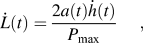
where a(t) is the radius of the projected contact area between the probe and the indented surface. Note that, for a linear viscoelastic material that undergoes no concurrent plastic deformation, Eq. (17) is valid, as can be readily observed from differentiation of Eq. (4).
A. Analytical proof of rescaling formula for creep experiments
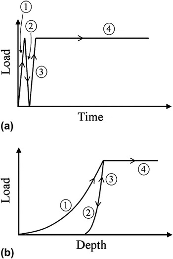
Instead of considering a typical contact creep experiment (for which the contact load is increased up to P max and maintained constant while h(t) is acquired), let us consider a thought experiment (see Fig. 3) with the following load history: (i) instantaneous loading to P max, (ii) instantaneous and complete unloading to P = 0, (iii) instantaneous reloading to P max, and (iv) acquisition of creep response at maintained P max.
(a) Load versus time scheme; (b) load versus depth response of the thought experiment for (1) instantaneous loading, (2) instantaneous unloading, (3) instantaneous reloading, and (4) creep phase.

The indentation depth h(t) over the creep phase of this thought experiment is the same as over the creep phase of a typical contact creep experiment. We assume that the reloading–creep phase exhibits no plasticity. Under this assumption, which we will discuss later, the viscous reloading–creep phase can be considered itself as an indentation creep experiment in a viscous material with no instantaneous plasticity. The effect of instantaneous plasticity (plastic deformation took place during the preliminary loading–unloading cycle) on this indentation creep experiment is twofold. First, the indentation is imposed by a probe of known geometry on a surface. The surface is plastically deformed (by the preliminary loading–unloading cycle) and thus the geometry of the deformed surface is unknown. Second, the plastic deformation (which occurred during the preliminary loading–unloading cycle) leads to self-equilibrated residual stresses within the indented half-space. As a first step, we disregard the effect of residual stresses on the overall creep response. We then consider the perturbation of residual stresses.
In the absence of residual stresses, the effect of plasticity on the reloading–creep phase is limited to the deformation of the surface of the indented half-space. Thus, the reloading–creep phase is a linear viscoelastoplastic indentation on a surface that is no longer flat. We apply the method of functional equations to convert the reloading–creep phase into an equivalent elastic problem.Reference Lee and Radok3 The equivalent elastic problem is the elastic indentation of a surface of unknown geometry, which itself is equivalent to the elastic indentation of a flat surface by an indenter of unknown geometry. The relation between the contact radius a and the indentation depth h is defined as:

where f (h) is an unknown function. From an application of the BASh formula to the equivalent elastic problem,Reference Bulychev, Alekhin, Shorshorov, Ternovskii and Shnyrev28 the indentation stiffness S is linked to the indentation depth h as:

which, after integration, becomes:

where F(h) is the primitive of f(h) for which F(0) = 0. Following the methodology of previous works,Reference Vandamme and Ulm4 which derive analytical solutions for linear viscoelastic indentation, the contact creep compliance L(t) is linked to experimental data as:
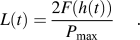
Finally, after differentiation, we obtain the relation of interest [Eq. (17)]:

which relates the measured creep response h(t) to the rate expression of the contact creep compliance L(t), independently of the plastic deformation that occurred during the loading phase.
We will later need the field solutions to the above problem. Let  ,
 , and
 be those stress, strain, and displacement field solutions, respectively.
Let us now consider the residual stresses consecutive to the infinitely fast loading–unloading cycle of our thought experiment. We restrict ourselves to a viscoelastoplastic half-space characterized by a time-invariant Poisson’s ratio.
We consider first a loading–unloading cycle with no further reloading. Let  ,
 ,
 , and
 be the residual stress, the resulting displacement, total strain, and plastic strain generated by the instantaneous loading–unloading cycle in the half-space, respectively. Following the reasoning above, we show that the solution to this residual stress problem verifies:
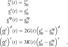
where  ,
 , and
 . Therefore, under the assumption of a time-invariant Poisson’s ratio, the residual stresses resulting from the instantaneous loading–unloading cycle result in no recovery.
We consider now the creep phase of the thought experiment and show that the stress  , strain
 , and displacement
 are its solution, where
 ,
 , and
 are defined previously. Indeed, since
 and
 both verify the field Eqs. (7) and (9), we infer from the assumption of linear superposition that this compatibility will also hold for the sum of these field equations. Moreover, the solution to the creep experiment with no residual stresses
 satisfies the boundary condition [Eq. (10)] of the creep problem; the solution to the residual stress problem
 satisfies the zero boundary conditions everywhere. Thus, their sum still satisfies the boundary condition [Eq. (10)] of the creep problem. Therefore,
 is the solution to an indentation creep experiment in a viscoelastoplastic material.
The presence of residual stresses due to the loading–unloading cycle only introduces a constant offset in the indenter probe displacement (with regard to the indenter probe displacement of the problem considered in the absence of residual stress) and has no influence on the indenter penetration rate. Therefore, relation [Eq. (17)] can be applied to indentation creep experiments on viscoelastoplastic materials for which the creep is linear with regard to stresses. Note however that, strictly speaking, the analytical proof is only valid under the assumption of a time-invariant Poisson’s ratio. This assumption is verified for an incompressible material with deviatoric creep, for which the Poisson’s ratio ν(t) = 1 / 2 is indeed time-invariant and for which Eq. (17) therefore holds.
B. Numerical validation
As in the case of load relaxation analytical and numerical predictions, to assess the validity of Eq. (17) we conducted numerical simulations of conical and parabolic indentation creep experiments on a viscoelastoplastic material via the finite element method.
1. Numerical implementation
Numerical simulations were carried out with ABAQUS (Dassault Systemes). The included half-cone angle of the probe was again θ = 70.32o. An axisymmetric mesh refined in several steps around the indenter probe was used. To better capture the evolution of the contact area over the creep phase, extra refinement of the mesh was introduced around the eventual edge of the contact area during the creep phase (see Fig. 5). The whole mesh consisted of 15,656 nodes and of 15,115 CAX4 (4-node bilinear) elements. The load applied to the indenter probe was imposed, and the displacement h(t) of the probe was output from the numerical simulation. Due to the extra refinement of the mesh, the elements in the vicinity of the edge of the contact area during the creep phase were smaller than one four-hundredth of the contact radius. To simulate an instantaneous loading, viscous properties were dismissed during the loading phase. As a result, the load history applied to the indenter corresponded to a Heaviside function.
Ratio of the contact creep rate  obtained from the numerical simulations and Eq. (17) to the contact creep rate
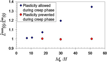
 obtained from the analytical solution Eq. (24) versus M 0 / H when plasticity is allowed during the creep phase (blue diamonds) and when plasticity is prevented during the creep phase (red circles). For all simulations, the ratios remained constant within ±2% over the creep phase.

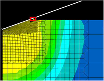
Deformed mesh and von Mises stresses during the creep phase for the simulation with σ y / E 0 = 10−2. The plastic phenomena occurring during the creep phase take place in the indicated rectangle.

The viscous behavior of the indented material was modeled by the deviatoric Maxwell creep model, characterized by its viscosity η M. The instantaneous Poisson’s ratio was ν0 = 0.499. The material was elastic perfectly plastic. The incompressible plastic flow was modeled with an associated von Mises plasticity model. The yield strength-to-Young’s modulus ratio σ y / E 0 was varied from 10−2 to 10−1. The duration of the creep phase was equal to three times the characteristic viscous time of the material η M / M 0. As in the case of load relaxation simulations, here large displacements were considered.
2. Results and discussion
The indentation modulus  and the maximal load P max were input in the numerical simulation. The depth history h(t) and contact radius a(t) were output from the numerical simulation. With Eq. (17), we calculated the rate
 of the contact creep function.
 was then compared with a linear viscoelastic analytical solution for deviatoric Maxwell creep model from the literatureReference Vandamme and Ulm4:

For all simulations,  was constant within ±2% over the creep phase.
 is displayed in Fig. 4 versus M 0 / H, where H = P max / A c is the effective hardness calculated at the end of the loading phase.
On average, Eq. (17) overestimated the contact creep compliance rate. This overestimation increased with an increasing M 0 / H ratio, i.e., with a decreasing σ y / E 0 ratio. At most, an overestimation of approximately 36% was obtained for simulations of M 0 / H ≈ 51. In contrast, for “low” M 0 / H ratios (M 0 / H ≤ 10), Eq. (17) gave an almost perfect evaluation of the contact creep compliance rate as predicted by numerical calculations. To identify the reason for the discrepancy with Eq. (17), the simulations were also conducted in the absence of plasticity during the creep phase: for any σ y / E 0 ratio, Eq. (17) was then in perfect agreement with the analytical solution Eq. (24). This observation proves that instantaneous and time-independent plastic phenomena do occur during the creep phase, and that Eq. (17) overestimates the indentation creep compliance rate because of this occurrence of plastic deformation during the creep phase. The occurrence of plastic deformation during the creep phase may be surprising. Indeed, over the creep phase, the contact area between the probe and the indented surface increases and, as a result, the average stress below the indenter, i.e., a value mathematically equivalent to the indentation hardness H, decreases. We observed in these finite element simulations that the plastic deformation occurred in a very localized fashion, around the perimeter of the contact area (see Fig. 5). For the simulations in which plasticity was allowed during the creep phase, we increased the mesh resolution around the contact edge, but this had no effect on the ratio displayed in Fig. 4. This observation suggests that the occurrence of plastic deformation over the creep phase is not a numerical artifact.
In summary, Eq. (17) provides a link between experimental data and the contact creep compliance rate, even when instantaneous plasticity occurs during the initial loading phase. However, Eq. (17) does not correct for the occurrence of plasticity during the creep phase, which can be significant for materials exhibiting a high ratio of M / H.
C. Specific case of short indentation creep experiments
Practically, the creep phase of an indentation creep experiment is typically limited to a few minutes, often because sample displacement rates become competitive with displacement signal drift rates over longer data acquisition durations. In such cases, one may wish to consider the specific case of a rather brief measurement of the material creep response. For short creep phases, the change in contact radius over the creep phase can be neglected. To first order, the contact radius is thus constant over the creep phase, i.e., a(t) ≈ a U, where a U is the contact radius just before unloading. Under this approximation, Eq. (17) yields:
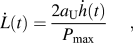
where  and P max are readily available from experimentation, and a U can be estimated, for instance with the Oliver and PharrReference Oliver and Pharr29 method.
In order for the above equation to be applicable, one may want to limit the change of contact radius over the creep phase to 10%. Assuming in first order that the ratio of the contact depth to the penetration depth remains constant during this phase, one can impose this restriction by choosing the duration of the creep phase such that the penetration depth just after creep is less than 10% greater than the penetration depth just before creep.
IV. APPLICATION: CONTACT CREEP LOADING OF POLYSTYRENE
Equation (17) was derived for a time-dependent behavior which is linear with regard to applied stresses. For most materials, this assumption proves too restrictive. The purpose of this section is to understand whether the results presented above can be extended beyond linear creep behavior. For such materials, we ask whether it is possible to apply Eq. (17) to obtain a viscous material property which is independent of the loading profile and thus physically meaningful. To answer this question, we carried out indentation creep experiments using a sharp Berkovich probe on polystyrene, an amorphous homopolymer that is glassy at room temperature. This material is known to exhibit both creepReference Tweedie and Van Vliet5 and long-term plastic deformationReference Tweedie and Van Vliet30 under typical indentation loading profiles which use a sharp (e.g., Berkovich trigonal pyramid) indenter comprising a stiffer material such as diamond. To solicit different relative amounts of plasticity, different maximum loads and loading durations were considered.
A. Materials and methods
Indentation creep experiments were conducted with a NanoTest 600 instrumented indenter (Micro Materials LLC, Wrexham, United Kingdom) on polystyrene (DuPont, Wilmington, DE). Different loading rates were achieved with a prescribed trapezoidal load history: the load was increased linearly up to P max, held constant during the creep phase, and then decreased linearly. By varying both the load magnitudes and loading times τ L by one order of magnitude, a large range of loading rates  was achieved, covering two orders of magnitude. These experiments were carried out with three load levels (P max = 3, 10, and 30 mN) and three loading times (τ L = 3, 10, and 30 s), yielding a total of nine load cases that varied the loading rate
 from
 mN·s−1 to
 mN·s−1. The unloading phase duration τ U was chosen equal to the loading phase duration. For each experiment, the creep phase was 30 s in duration. Each load case was repeated three times, yielding a total of 27 indentations on polystyrene.
For the 27 experiments, the change in depth h(t) over the creep phase was on average less than 10%. Assuming in first order a constant h c / h ratio, where h c is the contact depth, we estimated a change in contact radius over the creep phase less than 10%, so that the contact creep compliance rate was calculated with Eq. (25). The 27 experiments yielded M 0 / H = 24.1±1.7, where the indentation modulus M 0 was calculated with the Oliver and PharrReference Oliver and Pharr29 method, and H was the indentation hardness at the end of the holding phase. Based on the small change in contact radius over the holding or creep phase, H was considered a good estimate of the average pressure at the beginning of the creep phase. In conjunction with the numerical results displayed in Fig. 4, we estimated the overestimation of the contact creep compliance rate from Eq. (25) to be about 10%. This error is of the same order as, but of opposite direction, to the error induced by neglect of the radial contraction of the indented material by elastic solutions; the latter effect is commonly included in the empirical β-factor.Reference Oliver and Pharr27 Therefore, no correction factor was included to take into account the potential effect of plastic phenomena occurring during the creep phase.
The estimation of the contact radius before unloading was performed with the Oliver and PharrReference Oliver and Pharr29 method. We fit the function 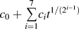 to the experimental change in indentation depth during the creep phase. From an analytical differentiation of the fit function, we obtained
 and applied Eq. (25).
B. Results and discussion
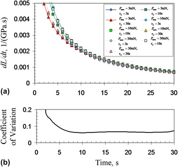
Figure 6 displays the contact creep compliance rate  over the creep phase for the different load histories. The responses show some scaling at the very beginning of the creep phase only: the larger the loading rate
 , the larger the measured contact creep compliance rate
 . This trend is the consequence of a well-known viscoelastic effect. After a few seconds, however, this effect becomes negligible. Indeed, the time evolution of the coefficient of variation (mean normalized by standard deviation) of the 27 experiments, which is also displayed in Fig. 6, is as follows: for t ≥ 7 s, the coefficient of variation is smaller than 7% and almost constant over the creep phase. Therefore, after a few seconds in the creep phase, the measured rate of change of the creep compliance
 for polystyrene is independent of the load profile. This application demonstrates that Eq. (25) provides a physically meaningful, time-dependent property of the material (i.e., independent of the load profile).
(a) Contact creep compliance rate  of polystyrene versus time for different load cases and (b) coefficient of variation of the 27 measured contact creep compliance rates. For each load case, only the mean value of the three creep tests is displayed: for t ≥ 5 s, the coefficient of variation of the three tests corresponding to one load case was always below 5%.

V. CONCLUSIONS
We have derived simple equations to obtain, under contact creep loading, the contact relaxation modulus M(t) and the contact creep compliance rate  of the indented viscoelastoplastic material. These relations take into account the occurrence of plasticity during the loading phase, which at least for conical probe geometries is unavoidable. These equations are valid for any axisymmetric indenter shape, for large deformations, and for any type of instantaneous plasticity. If necessary, the measured M(t) and
 can then be fit to analytical solutions available in the literature for several rheological models,Reference Vandamme and Ulm4 although Eqs. (6), (17), and (25) can be used with any rheological model of the time-dependent behavior. The analytical approach was developed under the following assumptions: time-invariant material Poisson’s ratio, negligible plastic deformation during the relaxation or creep phase, linear dependence of the viscous properties with regard to applied stresses. If any of these assumptions breaks down, the measurement of viscous properties by means of the equations here derived will be less accurate.
For indentation relaxation experiments, we proved analytically that the relaxation phase is viscous only. For indentation creep experiments, numerical simulations showed that time-independent plastic phenomena do occur during the creep phase in a very localized manner around the edge of the contact area. Equation (17) corrects for the unavoidable occurrence of plasticity during loading, but not for the potential occurrence of plasticity during the creep phase. In the specific case of Berkovich indentation, the numerical simulations performed (see Sec. III.B) provide a correction factor to Eq. (17), which takes into account the potential occurrence of plastic deformation during the creep phase.
For sufficiently short indentation creep experiments, the change in contact area over the creep phase becomes negligible and Eq. (17) becomes:
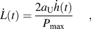
where a U is the contact radius at the beginning of the unloading phase.  and P max are readily available from experimentation, and the estimation of a U (for instance with the Oliver and PharrReference Oliver and Pharr29 method) is required for the measurement of the indentation elastic modulus M 0 and hardness H. Therefore, in addition to routine indentation analysis, for which M 0 and H are calculated, the calculation of the contact creep compliance rate from Eq. (26) can be achieved readily. These results then provide an additional means to quantify the viscoelastic characteristics of viscoelastoplastic materials, independently of loading profile.
ACKNOWLEDGMENTS
K.J. Van Vliet acknowledges G.S. Blackman of the DuPont Nanotechnologies Core Team for providing the polystyrene sample used in these experiments, as well as partial funding by the Institute for Soldier Nanotechnologies under Contract W911NF-07-D-0004 with the Army Research Office.