INTRODUCTION
The inertial fusion energy (IFE) is based on high compression (Nuckolls et al., Reference Nuckolls, Wood, Thiessen and Zimmermann1972; Azechi et al., Reference Azechi, Jitsuno, Kanabe, Katayama, Mima, Miyanaga, Nakai, Nakai, Nakaishi, Nakatsuka, Nishiguchi, Norreys, Setsuhara, Tagagi, Yamanaka and Yamanaka1991; Eliezer et al., Reference Eliezer, Murakami and Martinez Val2007; Mima et al., Reference Mima, Murakami, Nakai, Eliezer, Eliezer and Mima2009). The reasoning is that it is energetically cheaper to compress than to heat and the nuclear reactions are proportional to density square. IFE of deuterium–tritium (DT) requires high compression (~1000) and in particular the aneutronic fusion of the proton–boron11 (Eliezer & Martinez Val, Reference Eliezer and Martinez Val1998; Son & Fisch, Reference Son and Fisch2004; Leon et al., Reference Leon, Eliezer, Piera and Martinez Val2005) needs extremely huge compression (>10,000). The high compression is achieved by shock waves and by the accumulation of matter during the stagnation of the implosion of the target shell.
The shock waves in laser plasma interaction (Eliezer, Reference Eliezer2002) have played an important role in the study of IFE (Velarde & Carpintero-Santamaria, Reference Velarde and Carpintero-Santamaria2007). In 1974, the first direct observation of a laser–driven shock wave was reported (van Kessel & Sigel, Reference Van Kessel and Sigel1974). A planar solid hydrogen target was irradiated with a 10 Joule, 5 ns, Nd laser, and a pressure of about 2 Mbar was measured. Twenty years after this experiment, the NOVA laser from Lawrence Livermore National Laboratory created a pressure of 750 ± 200 Mbar (Cauble et al., Reference Cauble, Phillion, Hoover, Holmes, Kilkenny and Lee1993). This was achieved in a collision between two Au foils, where the flyer (Au foil) was accelerated by a high intensity X–ray flux created by the laser–plasma interaction. More recently (Azechi et al., Reference Azechi, Sakaiya, Watari, Karasik, Saito, Ohtani, Hosoda, Shiraga, Nakai, Shigemori, Fujioka, Murakami, Johzaki, Gardner, Colombant, Bares, Velikovich, Aglitskiy, Weaver, Obenchain, Eliezer, Kodama, Norimatsu, Fujita, Mima and Kan2009), with the Osaka GEKKO XII laser a plastic foil was accelerated directly by the laser beams to about 1000 km/s.
In order to achieve nuclear fusion ignition, a mega–joule laser with few nanoseconds pulse duration has been constructed in the United States (Moses, Reference Moses2009). The central spark ignition of DT is expected soon. In this scheme, the target and the driver pulse shape are designed in such a way that only a spark at the center of the compressed fuel is heated and ignited (Lindl, Reference Lindl1997; Rosen, Reference Rosen1999; Atzeni & Meyer-ter-Vehn, Reference Atzeni and Meyer-ter-Vehn2004). The rest of the fuel is heated by α particles produced in the DT reactions.
In order to ignite a DT target with significantly less than one (or few) MJ of energy, it was suggested (Basov et al., Reference Basov, Guskov and Feoktistov1992; Tabak et al., Reference Tabak, Hammer, Glinsky, Kruer, Wilks, Woodworth, Campbell, Perry and Mason1994) to separate the drivers that compress and heat the target. This idea is called fast ignition (FI). FI triggers are not in a central spark, but in a secondary interaction of an igniting driver of a very short duration, such as a multi petawatt (PW) laser beam. The PW laser is supposed to form a channel during a few picoseconds (ps) in the plasma atmosphere and to ignite a part of the fuel at the stagnation point of the implosion. For this purpose, it was estimated that ignition requires about 10 kJ of laser energy during a duration of 10 ps with irradiance on the order of 1020 W/cm2 (however, the transport of energy from the critical surface into the compressed fuel is still a topic of intense research and by no means this problem is solved).
The FI problem is that the laser pulse does not penetrate directly into the compressed target with an electron density on the order of 1024 cm−3. Therefore, many schemes of FI were suggested: (1) the laser energy is converted into electrons that ignite the target (Norreys et al., Reference Norreys, Allot, Clarke, Colliers, Neely, Rose, Zepf, Santala, Bell, Krushelnick, Dangor, Woolsey, Evans, Habara, Norimatsu and Kodama2000); (2) the laser energy is converted into protons that ignite the target (Roth et al., Reference Roth, Cowan, Key, Hatchett, Brown, Fountain, Johnson, Pennington, Snavely, Wilks, Yasuike, Ruhl, Pegoraro, Bulanov, Campbell, Perry and Powell2001); (3) since the heating process in the previous proposals is not confined and furthermore it is necessary to avoid preheating, a Au cone (Au density/solid DT density ~100) was stuck into the spherical pellet (Kodama et al., Reference Kodama, Norreys, Mima, Dangor and Evans2001). The implosion of this configuration at Osaka University lasers (9 beams for compression: 2.5 kJ, 1.2 ns flat top pulse, 0.5 PW for heating pulse) yielded 3 orders of magnitude more neutrons than in the case without a cone; (4) FI is induced by plasma jets (Martinez Val & Piera, Reference Martinez Val and Piera1997; Velarde et al., Reference Velarde, Ogando, Eliezer, Martinez Val, Perlado and Murakami2005) that are induced by the same laser system that compresses the pellet; (5) the FI is done by plasma flow created from a thin exploding pusher foil (Caruso & Strangio, Reference Caruso and Strangio2001; Guskov, Reference Guskov2001); (6) plasma blocks for FI were also suggested (Hora et al., Reference Hora, Badziak, Glowaks, Jablonski, Skladanovski, Osman, Cang, Zhang, Miley, Peng, He, Zhang, Rohlena, Ullschmied and Jungwirth2005); (7) Murakami et al. (Reference Murakami, Nagatomo, Azechi, Ogando, Perlado and & Eliezer2006) revived the old impact fusion with the help of the cone. This type of experiments (Azechi et al., Reference Azechi, Sakaiya, Watari, Karasik, Saito, Ohtani, Hosoda, Shiraga, Nakai, Shigemori, Fujioka, Murakami, Johzaki, Gardner, Colombant, Bares, Velikovich, Aglitskiy, Weaver, Obenchain, Eliezer, Kodama, Norimatsu, Fujita, Mima and Kan2009) yielded 100–fold increase of neutrons during the collision of a deuterated polystyrene (DT) foil accelerated to 600 km/s with the pre–compressed DT target; (8) last but not least, Betti et al. (Reference Betti, Zhou, Anderson, Perkins, Theobald and Solodov2007) suggested the idea of combining the FI with a laser induced strong shock wave.
In Section 2, laser induced shock wave FI is discussed in the context of multi–shock wave compression. In Section 3, a disturbing instability is pointed out in the FI shock wave scheme. Section 4 analyses the foil acceleration potential for FI. Finally the conclusion Section tries to put the different fast ignition ideas into a perspective.
1. LASER INDUCED MULTI-SHOCK WAVE COMPRESSION AND FAST IGNITION
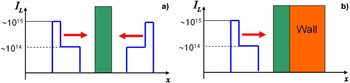
Multi shock wave compression with shock wave collisions using tailored laser pulses were already suggested (Jackel et al., Reference Jackel, Salzmann, Krumbein and Eliezer1983) before the idea of FI was explicitly published (Basov et al., Reference Basov, Guskov and Feoktistov1992; Tabak et al., Reference Tabak, Hammer, Glinsky, Kruer, Wilks, Woodworth, Campbell, Perry and Mason1994). In Figure 1, the schematic configurations, in planar one–dimensional (1D) geometry, are given for the simulation of the tailored laser pulses used in Jackel et al. (Reference Jackel, Salzmann, Krumbein and Eliezer1983) for (1) collision between two shock waves, and (2) shock collision with a very high density (wall). The laser irradiance is in the domain 1014–1015 W/cm2, the target is Al and the wall has a density of 270 g/cm3. The highest compressions (ρ/ρ0) and pressures (P) derived for the (1) and (2) configurations were accordingly: (ρ/ρ0) = 12, 40; P = 40 Mbar, 300 Mbar. The simulations are using the hydrodynamic equations based on mass, momentum, and energy conservations together with the equations of state (Eliezer et al., Reference Eliezer, Ghatak and Hora2002; Eliezer & Ricci, Reference Eliezer and Ricci1991; Zeldovich & Raizer, Reference Zeldovich and Raizer1966).
(Color online) Schematic configurations of the tailored laser pulses used in Jackel et al. (Reference Jackel, Salzmann, Krumbein and Eliezer1983) for (a) collision between two shock waves, and (b) shock collision with a very high density (wall). The laser irradiance is given in W/cm2 units, the target is Al and the wall has a density of 270 g/cm3.

The mass, momentum, and energy conservation that relates between the states before and after the transition of the shock wave, in the laboratory frame of reference, are given accordingly by the following equations:
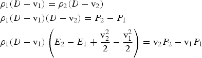
D is the shock wave velocity, ρ is the density, P is the pressure, v is the fluid flow velocity, and E is the energy per unit mass, define the state of fluid before (subscript 1) and after (subscript 2) the shock wave transition. For a given initial state defined by [ρ1, P 1, E 1, v 1] one cannot solve the above equations without the knowledge of the equations of state, e.g., E = E(P,ρ). For example, the ideal gas equations of state is given by

γ = C P/C V is the ratio of the heat capacities at constant pressure and constant volume. For the fully ionized DT plasma (electrons and ions assumed to have the same temperature) one gets the ideal gas temperature T (independent of γ)

where k B is the Boltzmann constant and m i ≈ 2.5m p (m p is the proton mass) is the average ion mass. It is also useful to check the relations of a strong shock wave, i.e., P 2 >> P 1, in an ideal gas

From these equations with γ = 5/3, one requires a flow velocity of 1.52 × 108 cm/s for a thermonuclear temperature of k BT = 10 keV.
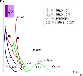
This very high flow velocity is obtained because heating by a shock wave is not efficient. Therefore, a sequence of shock waves that approach the limit of adiabatic compression is favorable. See the schematic Figure 2 for the P-V (pressure – specific volume) diagram that describes one strong shock wave H and a series of shock waves H k that approach the isentrope S. The different domains of solid, liquid, solid–liquid(L + S) mixture, vapor, liquid–vapor (L + V) mixture, and plasma are also shown. ICF is the desired domain of fusion ignition in the different inertial confinement schemes. As one can see from this figure, it is necessary to approach the isentrope for IFE.
(Color online) Schematic P–V (pressure – specific volume) diagram that describe one strong shock wave H and a series of shock waves H k that approach the isentrope S. The different domains of solid, liquid, solid–liquid (L + S) mixture, vapor, liquid–vapor (L + V) mixture and plasma are shown. ICF is the desired domain of fusion ignition in the different inertial confinement schemes. c.p. is the critical point and T = 0 is the zero isotherm.

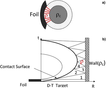
Another way to reduce the flow velocity for a given desired temperature is by the collision of a flyer with the DT fuel bordered with a very high density matter (wall). See Figure 3. In Figure 3, the spherical configuration is shown where the high compressed fuel with a density ρc, on the order of few hundred g/cm3, is obtained by the laser (in the direct drive) or soft X–rays (in the indirect drive) compression of the DT shell during its stagnation state. In Figure 3b, the 1D planar analogy idealization is shown. State 1 describes the initial DT fuel before the foil impact. State 2 is after the transition of the first shock wave. After the collision of this shock wave with the wall, defined by its very high density, a second shock is passing through the fuel as represented by State 3. A series of small shock waves and rarefactions waves follow through the fuel and to a good approximation, State 4 can be approximated by an adiabatic compression. For this approximation, it is important that the flyer has also a high density. Possible candidates for the flyer are: Au (ρ0 = 19.32 g/cm3), platinum (ρ0 = 21.45 g/cm3), etc.
(Color online) (a) the spherical configuration is shown where the high compressed fuel with a density ρc, is obtained by the compression of the DT shell during its stagnation state. (b) the 1D planar geometry is shown. State1 describe the initial DT fuel before the foil impact. State 2 is after the transition of the first shock wave. After the collision of this shock wave with the wall a second shock is passing through the fuel as represented by state 3. State 4 shows the adiabatic compression.

The first shock wave density, pressure, and temperature are derived from Eq. (4). After the transition of the second shock (that returns from the wall) we get for the ideal gas approximation with γ = 5/3,

For the last stages, the following thermodynamic relations for an ideal gas equation of state can be used
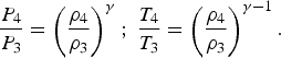
In order to estimate all the parameters at this stage, the energy conservation equation between Stages 3 and 4 is required. The hot spot thickness x 4 is determined from the requirement that the alpha particles created in the DT reactions are absorbed in this hot spot domain, namely ρ4x 4 = 0.3 g/cm2. Within this approximation, the energy equation, for a flyer with density ρf, thickness x f, cross–section area S and velocity v f, is:
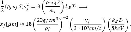
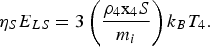
The second equation describes the foil thickness in practical units, in particular, for a Au foil with a velocity 3 × 108 cm/s, the minimum required DT fusion temperature of 5 keV, the minimum ρ4x 4 = 0.3 g/cm2 for a absorption one gets a foil thickness of about 20 µm. For a foil with a cross–section of 100 µm × 100 µm, the kinetic energy of this foil is 20 kJ. It is interesting to point out that hydrodynamic simulation (Azechi et al., Reference Azechi, Sakaiya, Watari, Karasik, Saito, Ohtani, Hosoda, Shiraga, Nakai, Shigemori, Fujioka, Murakami, Johzaki, Gardner, Colombant, Bares, Velikovich, Aglitskiy, Weaver, Obenchain, Eliezer, Kodama, Norimatsu, Fujita, Mima and Kan2009) demonstrates that ignition occurs with impactor energy of only 10 kJ. However, for a typical coupling efficiency (ηs) of 20% from the laser energy E Ls to the fuel heat energy, one requires 100 kJ consistent of driver in order to ignite the hot spot. This follows from the energy conservation for the system “driver (laser energy in direct or indirect drive) — hot spot”
Finally, solving Eqs. (4) to (7) for the initial condition (ρ, P, T)1= (0.2 g/cm3, 10 bar, 300 K) one gets for the hot spot for the above flyer with ideal equations of state plasma with γ = 5/3:
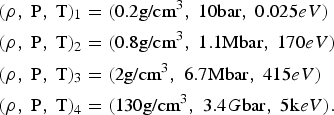
In order to compress and heat the main fuel, defined by its density ρC, pressure P C, temperature T C and mass M C, one requires driver energy E LC given by the following energy conservation

ηC is the efficiency from laser to thermal energy and ɛF is the Fermi energy. The effective temperature T C and pressure P C are defined via a parameter α, related to the degenerate quantum pressure P deg: P C = 2n ek BT C = αP deg = (2/5)αn eɛF ~αρC5/3, where n e is the electron density. Simulations show that α equals about 3 is a reasonable number. In the above example, a gain of 100 can be obtained for M C = 0.5 mg of DT fuel compressed to 300 g/cm3.
2. AN INSTABILITY PROBLEM
As already mentioned in the introduction, it was suggested (Betti et al., Reference Betti, Zhou, Anderson, Perkins, Theobald and Solodov2007; Ribeyre et al., Reference Ribeyre, Schurtz, Galera and Weber2009; Lafon et al., Reference Lafon, Ribeyre and Schurtz2010) to combine FI with a laser induced strong shock wave. At the stagnation phase, prior to the final stagnation, a strong shock wave is launched to ignite the hot spot. The shock is produced by intense spike in the laser pulse.
The absorption layer in laser plasma interaction is very small around the critical surface. In this case, the laser pressure Π can induce singularities in the pressure and density profile at the critical surface. The laser pressure is given at the critical surface by Π = (I L/c) · (1 + R), where I L is the laser irradiance, R is the laser reflection at the critical surface and c is the speed of light. For example, Π = 5 Mbar for I L = 1016 W/cm2 with R = 50%. In general, for high laser intensities I L > 1015 W/cm2, the shock wave jump conditions (Eq. (1)) in the frame of reference moving with the absorption layer at the critical surface are given by
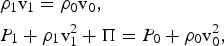
where the subscript zero and one refer to the undisturbed and the disturbed regions accordingly at the critical surface. The energy invested at the critical surface is so high that an isothermal jump (in density and pressure) occurs. Therefore, one can assume that the speed of sound before (region 0) and after (region 1) the critical surface are equal, namely
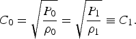
The solution of Eqs. (11) and (12) is
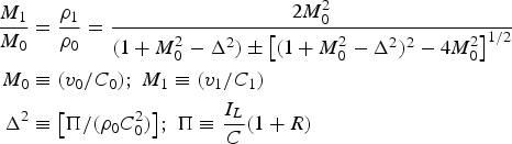
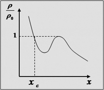
M 0 and M 1 are the Mach number in domain 0 and 1 accordingly. Since ρ1/ρ0 is real, the […] term in the denominator of Eq. (13) is positive. This constrain implies two solutions: For M 0 ≥ 1 + Δ one gets a (compression) shock wave: ρ1 > ρ0, M 0 < M 1, while the case 1 − Δ ≥ M 0 describes a rarefaction wave: ρ1ρ0, M 0 > M 1. This situation can lead to undesired instability (Eliezer et al., Reference Eliezer, Martinez Val and Deutsch1995) as shown in Figure 4.
A presentation of the density profile around the critical surface denoted by x c.

3. CONCLUSION
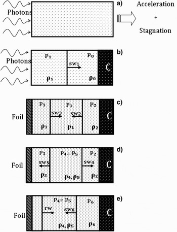
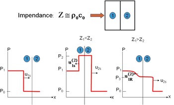
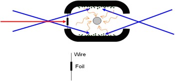
The FI models with a laser induced shock wave or a foil induced shock wave are described in Figure 5 where the sequence of shock waves (sw) and rarefaction waves (rw) are described. P and ρ denote the appropriate pressures and densities. The pre–compressed target is denoted by C. In Figure 5a, the laser driver (direct drive) or the soft X–rays (indirect drive) accelerate the spherical shell and compresses the target during the stagnation period. At this stage, the extra laser shock wave (sw1) is described, while in Figure 5c, the collision between sw1 and the compressed matter C creates a second and stronger shock wave (sw2). For this to happen, one requires that the impedance (density × speed of sound) of the core is higher than that of the matter next to it, as described schematically in Figure 6. The additional shock wave (sw3) in Figure 5c can be created by a higher laser intensity pulse (I L > 1015 W/cm2) or by the acceleration of a foil for inducing a shock wave for FI as described in Figure 7. The ignition is derived in the regions described in Figures 5d or 5e and analytically described by Eq. (7) and the last set of thermodynamic parameters in Eq. (9).
The sequence of shock waves (sw) and rarefaction waves (rw) in the model of shock wave induced FI. P and ρ denote the appropriate pressures and densities. The pre-compressed target is denoted by C.

(Color online) The shock wave transition between materials with different impedances.

(Color online) The acceleration of a foil for inducing a shock wave for FI.

Another possible driver for the last stage of shock wave driver can be a cluster ion beam (Eliezer et al., Reference Eliezer, Martinez Val and Deutsch1995; Deutsch & Tahir, Reference Deutsch and Tahir1995; Tahir et al., Reference Tahir, Lutz, Geb and Hoffmann1997) with the following parameters: Energy on the order of 105 J, a flux of about 1017 W/cm2 during a period of the order of 100 ps.
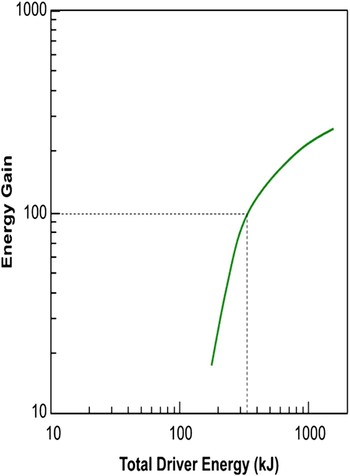
The energy gain for the calculations described in the previous section is given in Figure 8. The gain as a function of the driver energy is for DT fuel with a mass MC = 0.5 mg and a density 300 g/cm2. The spark ignitor has the thermodynamic parameters given in Eq. (9) (denoted by subscript 4). The equation of state parameter α for the compressed fuel is 3. The 100 gain is obtained with an input energy of about 230 kJ.
(Color online) Energy gain as a function of the driver energy for a pre-compressed core of DT with a density 300 g/cm2. The spark ignitor has the thermodynamic parameters given in Eq. (9) (denoted by subscript 4). The equation of state parameter α for the compressed fuel is 3.

In summary, it seems that FI needs less laser energy than the other schemes. Taking into account that one needs a driver with repetition on the order of 10 Hz, this is a very important argument in favor of FI. Therefore FI has the potential to be the best route to achieve nuclear fusion as an energy source. However, much more work and new ideas are needed to reach the desired energy.