I. INTRODUCTION
Mg-rare earth (Mg-RE) alloys, as one of the lightest structural metal materials, have found more and more applications in automotive and aerospace industries owing to their excellent mechanical performances at both room and elevated temperatures. Reference Mordike and Ebert1 RE plays an important role in purifying the molten metal, inflaming retarding of the melt, and improving the high-temperature mechanical properties and creep resistance of alloys. A significant progress is that the addition of a certain amount of Zn, Cu, or Ni into Mg-RE (RE = Y, Gd, Tb, Dy, Ho, Er, and Tm) alloys results in the formation of an long-period stacking ordered (LPSO) structure, which provides an alternative approach to improve mechanical properties of Mg alloys. Reference Zhu, Morton and Nie2–Reference Rong, Wu, Zhang, Sun, Chen, Peng and Ding7 Mg-RE alloys with the LPSO structure were reported to own high strength and high ductility simultaneously. Reference Xu, Xu, Shao and Han8 Additionally, an LPSO structure rich in RE and Zn brings about a higher Young’s modulus to Mg alloys. Reference Chino, Mabuchi, Hagiwara, Iwasaki, Yamamoto and Tsubakino9,Reference Tane, Nagai, Kimizuka, Hagihara and Kawamura10 Up to now five different kinds of LPSO structures (6H, 10H, 14H, 18R, and 24R) have been found in Mg alloys. Reference Zhu, Morton and Nie2,Reference Itoi, Seimiya, Kawamura and Hirohashi11–Reference Abe, Kawamura, Hayashi and Inoue13 Honma et al. Reference Honma, Ohkubo, Kamado and Hono14 investigated the effect of Zn addition on the age hardening of Mg–2.0Gd–1.2Y–0.2Zr (at.%) alloy and found that discontinuous 14H-type LPSO phases at grain boundaries as well as within grains in the over-aged condition enhanced the maximum tensile elongation. Nie et al. Reference Nie, Gao and Zhu15 discovered that the addition of 1–2 wt% Zn into Mg–6Gd–0.6Zr (wt%) alloy significantly enhanced the age hardening response and creep strength of the alloy due to a uniform and dense distribution of basal precipitate plates.
Cooling rate during solidification is another important factor affecting the microstructure and mechanical properties of Mg-RE alloys. Zhang et al. Reference Zhang, Yuan, Lu and Ding16 investigated the relationship between the (Mg,Zn)3RE phase and 14H LPSO phase in Mg–Gd–Y–Zn–Zr alloys solidified at different cooling rates and found that different types of LPSO structures and Mg-RE phases formed in alloys solidified at different cooling rates. Wang et al. Reference Wang, Wu, Hou, Chen, Zheng and Din17 compared Mg–Gd–Y–Zr alloys produced by metallic and sand mold casting. The results showed that although the type of phases was the same, sizes of grains and eutectics were different, which hence changed the solution process and mechanical properties of the alloys. Permanent metallic mold and sand mold are the most common casting molds in production practice. Metallic mold casting provides a high cooling rate during solidification, which refines the microstructure of alloys. Sand mold casting is widely used in producing Mg-RE aerospace parts, especially large thin-walled parts, for their complicated figures.
Mg–Y–Nd(–Gd)–Zr alloy series, among which the most well known are commercial WE43 (Mg–4.0Y–2.0Nd–1.0Gd–0.5Zr) and WE54 (Mg–5.0Y–2.5Nd–1.0Gd–0.5Zr) (wt%) alloys, provide a combination of mechanical and corrosion properties. Mg–Y–Nd(–Gd)–Zr alloys microalloyed with Zn have been studied recently. Reference Su, Liu and Wan18–Reference Zhang, Yang, Xiao, Wang, Zhang, Liu and Sakai21 Enhanced mechanical properties were obtained in the alloys after Zn addition. Because of low Zn content, no evident LPSO structure was formed and there was a lack of systematic research. Further investigations on the microstructure and mechanical properties of Mg–Y–Nd(–Gd)–Zr alloys with different contents of Zn cast at different solidification cooling rates have not been reported so far. In this work, a comparison of the microstructure and mechanical properties of Mg–3.0Y–2.5Nd–1.0Gd–xZn–0.5Zr (x = 0, 0.2, 0.5, and 1.0) alloys produced by metallic and sand mold casting was carried out. The LPSO structure was introduced into the Mg–Y–Nd–Gd–Zr alloy by addition of a certain amount of Zn and solidification at a certain cooling rate. Influence of Zn content and casting mold used on microstructure and mechanical properties of the alloys in different thermal conditions was discussed.
II. MATERIALS AND METHODS
Pure Mg, pure Zn, Mg–30Y, Mg–90Nd, Mg–90Gd, and Mg–30Zr (wt%) master alloys were melted in an electric resistance furnace under the protection of a mixed atmosphere of CO2 (99 vol%) and SF6 (1 vol%) to prepare the Mg–Y–Nd–Gd–Zn–Zr alloys. To minimize the amount and size of inclusions and oxide films, the melt was refined at 750 °C for 5 min before being poured into a metallic mold and a sand mold, which are exactly the same in size and shape. The metallic mold is made up of cast iron and the sand mold is made up of resin coated sands. The molds were preheated to ∼200 °C before casting. Chemical compositions of the obtained alloys were, thereafter, analyzed using an Inductively Coupled Plasma-Atomic Emission Spectroscopy and the results are listed in Table I. For convenience, the Mg–3.0Y–2.5Nd–1.0Gd–xZn–0.5Zr (x = 0, 0.2, 0.5, and 1.0) alloys are named as 0Zn, 0.2Zn, 0.5Zn, and 1.0Zn alloy, respectively.
Actual chemical compositions of the Mg–3.0Y–2.5Nd–1.0Gd–xZn–0.5Zr alloys (wt%).

Solution treatment at 525 °C for 8 h was carried out in a SO2 protective atmosphere. Quenching was performed in hot water above 90 °C because the alloys tend to crack when quenched in cold water at room temperature. Then the solution-treated alloys were isothermally aged at 225 °C for different hours in an oil bath to obtain age hardening curves.
Vickers hardness tests were conducted on a HV-300 tester (Shanghai Hugong Co., Ltd., Shanghai, China) using a 49 N load and 15 s holding time. Room temperature tensile tests were carried out on a Zwick/Roell Z100 test machine (Zwick, Ulm, Germany) at the strain rate of 1 × 10⁻³ s−1. Rectangular sheet specimens with a size of 15 × 3.5 × 2 mm for tensile tests were cut by electrical discharge machining. At least three samples were tested for each condition. The optical microstructure (OM) observation was performed on a ZEISS microscope (Carl Zeiss AG, Jena, Germany). Phenom XL scanning electron microscope (SEM; Phenom-World, Eindhoven, the Netherlands) equipped with an energy dispersive spectrometer (EDS) was used to observe the microstructure of the alloys and measure the distribution of elements. As-cast samples for the OM and SEM observation were etched in 4% HNO3 with ethanol and the as-quenched samples were etched in a solution of 4.2 g picric acid, 10 mL acetic acid, 10 mL water, and 70 mL ethanol. Phases in the as-cast alloys were identified by a Rigaku Ultima IV X-ray diffractometer (XRD; Rigaku Corp., Tokyo, Japan) with a resource of Cu Kα radiation at the scan rate of 4°/min.
III. RESULTS AND DISCUSSIONS
A. Microstructure and tensile behaviors of as-cast alloys
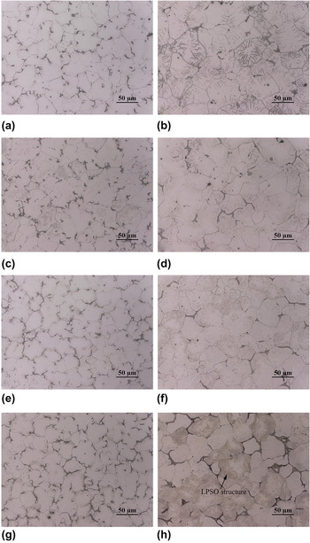
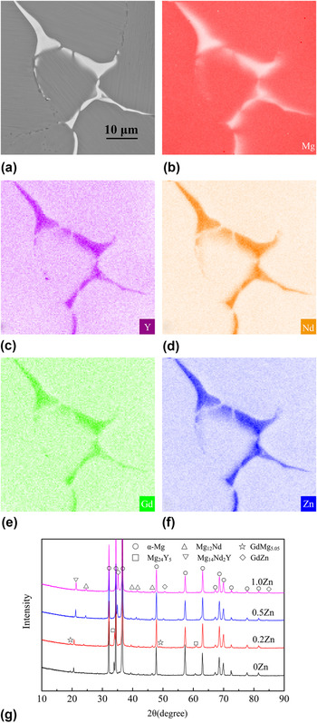
Figure 1 compares the OM of as-cast alloys with different Zn contents prepared using different molds. The as-cast alloys mainly consist of α-Mg matrix and eutectics. Figures 2(a)–2(f) shows the SEM image and corresponding EDS results of the eutectic by taking the sand mold casting 0.5Zn alloy as a typical representative. It can be observed that there exists a cluster of Y, Nd, Gd, and Zn in the eutectic, demonstrating that the eutectic is more than one compound but a mixture of several compounds. XRD patterns of the metallic mold casting alloys are shown in Fig. 2(g). Eutectics are mainly Mg24Y5, Mg12Nd, Mg14Nd2Y, and GdMg5.05 phases in 0Zn and 0.2Zn alloys, while Mg12Nd, Mg14Nd2Y, and GdZn phases in 0.5Zn and 1.0Zn alloys.
OM of the as-cast alloys produced by metallic and sand mold casting: (a) and (b) 0Zn; (c) and (d) 0.2Zn; (e) and (f) 0.5Zn; (g) and (h) 1.0Zn alloys.

SEM image (a) corresponding EDS results; (b) Mg map; (c) Y map; (d) Nd map; (e) Gd map; (f) Zn map and XRD patterns; and (g) showing the eutectics in as-cast alloys.

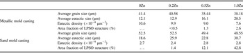
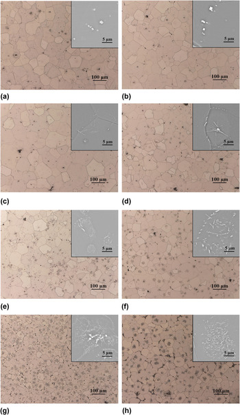
Average grain size, average eutectic size, (maximum distance between two points within the eutectic), and eutectic density (quantity of separate eutectics per 10,000 μm2) are listed in Table II. Average grain sizes of the metallic mold casting alloys (∼40 μm) are smaller than those of the sand mold casting alloys (∼50 μm). The density and size of eutectics in different alloys vary from each other. The eutectics distributed along grain boundaries in the sand mold casting alloys become much larger in size but lower in density than those in metallic mold casting alloys. Pang et al. Reference Pang, Wu, Liu, Sun, Zhang, Liu and Ding22 studied the effect of cooling rate at the range of 0.7–3.6 °C/s on the microstructure and mechanical properties of the sand-cast Mg–10Gd–3.0Y–0.5Zr (wt%) alloy. The finding showed that α-Mg grains were refined from 59 to 39 μm in average grain size and the volume fraction of the second phases increased from 17.6 to 24.5% by raising the cooling rate of solidification. The thermal conductivity of cast iron is above 30 W/(m K). Reference Holmgren23 The thermal conductivity of sand mold is closely related to porosity, saturation degree, and temperature of sands but is usually below 3 W/(m K). Reference Krajewski, Piwowarski, Zak and Krajewski24,Reference Chen25 According to Fourier’s Law, heat conduct in the metallic mold during solidification is much more quick, which improves the supercooling of melt and facilitates the nucleation and growth of grains. In this study, a higher cooling rate brought by metallic mold casting results in the refined grains, finer eutectics as well as enhanced mechanical properties, as detailed below. With the increasing Zn content, the eutectics get coarser. In the 0Zn alloys [Figs. 1(a) and 1(b)], eutectics are divorced. However, some eutectics in the 1.0Zn alloys [Figs. 1(g) and 1(h)] connect each other and become semicontinuous.
Average grain size, average eutectic size, eutectic density and area fraction of LPSO structure of/in the as-cast alloys.

The Lamellar-shaped LPSO structure is found to be inside α-Mg grains in the sand mold casting Zn-containing alloys. Its quantity increases with raising the Zn content, as is shown in Table II. Only a small amount of the LPSO structure in the 0.2Zn alloy [Fig. 1(d)] can be observed near eutectics, and the area fraction of the LPSO structure is nearly negligible. But for the 1.0Zn alloy [Fig. 1(h)], many α-Mg grains are filled with the LPSO structure. The area fraction of the LPSO structure in the 1.0Zn alloy is estimated to be 42.8%. Differently, the metallic mold casting Zn-containing alloys contain much less LPSO structures compared with the sand mold casting alloys. Hardly any LPSO structure can be observed in the 0.2Zn or 0.5Zn alloy [Figs. 1(c) and 1(e)]. It can be concluded that the LPSO structure forming during solidification closely links to the cooling rate. The simultaneous addition of Y and Zn decreases the stable and unstable stacking fault energies of the Mg alloy drastically, which facilitates the origination and growth of stacking faults (SFs). Reference Zhang, Fu, Fan, Tang, Peng and Ding26 The segregation of Y and Zn atoms to SFs is energetically favorable. The SFs can generate within the α-Mg at an early stage before the formation of the LPSO structure. After overlapping SFs having the correct spacing and subsequent diffusion-controlled segregation of Y and Zn atoms to the faults, the LPSO structure comes into being. Reference Zhu, Morton and Nie27 The nucleation and growth of α-Mg occur first during solidification, accompanied by the enrichment of alloying elements in the liquid. Naturally there exists diffusion of Zn and RE from liquid to primary α-Mg. Abe et al. Reference Abe, Kawamura, Hayashi and Inoue13 suggested that the formation of the LPSO structure in α-Mg originates from two ways: introducing SFs on a closed-packed plane and supplying the solute atoms (Zn and RE) to and adjacent to the faulted layers. Given enough time for atoms to diffuse under the long cooling process of sand mold casting, more SFs are transferred to the LPSO structure. It explains that the high content of Zn and low cooling rate promote the formation of the LPSO structure. Beyond that, it has been reported that the cooling rate after homogenization also has a influence on the origination of the LPSO structure in the Mg–Gd–Y–Zn–Zr alloy. Reference Xu, Nakata, Qiao, Zheng, Wu and Kamado28 As was revealed, 14H LPSO phases precipitated and grew across the whole grain because of the low cooling rate in the furnace, while no LPSO phase was visible in the water-quenched alloy. To control the microstructure and mechanical properties of the Mg–RE–Zn alloys by adjusting the cooling rate during solidification and heat treatment is important in real application.
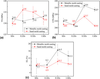
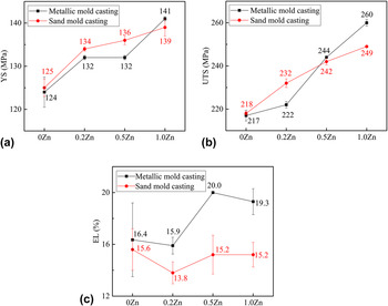
Tensile properties of the as-cast alloys are displayed in Fig. 3. Yield strength (YS) of the metallic and sand mold casting alloys with different contents of Zn is 130–136 MPa. The metallic mold casting 0Zn alloy shows higher YS than the sand mold casting 0Zn alloy as a result of finer grains and eutectics forming at a greater solidification cooling rate. On the contrary, sand mold casting 0.2Zn and 0.5Zn alloys, though with larger grains, exhibit a little bit higher YS. A higher area fraction of the LPSO structure in the sand mold casting Zn-containing alloy is responsible for the increase of YS. Li et al. Reference Li, Xu, Zeng, Wang, Sheng, Chen and Han29 suggested that the LPSO structure can enhance the mechanical strength of the Mg–Zn–Y alloy when the volume fraction of the structure was below 20.3%. The LPSO structure could perform a hardening role in strengthening alloy. Besides, (0001) basal slip dominates the deformation at room temperature. The interface of the LPSO structure is parallel to the (0001) plane, which hinders the basal slip. Reference Chen, Sandlöbes, Zeng, Li, Korte-Kerzel and Raabe30 Much higher stress is needed to activate the nonbasal slip. The values of elongation (EL) of 0Zn and 0.2Zn alloys are approximately equal but enhanced when Zn contents are 0.5 and 1.0%. Especially, the 0.5Zn alloys show the highest EL of 16.5% for the metallic mold casting alloy and 10.2% for the sand mold casting alloy. Keeping increasing Zn content from 0.5 to 1.0% leads to a remarkable decrease in ultimate tensile strength (UTS) and EL. Coarse eutectics make the 1.0Zn alloys own lower strength and ductility. UTS of the 0.5Zn alloys (233 MPa for the metallic mold casting alloy and 217 MPa for the sand mold casting alloy) is the highest in all alloys no matter cast by a metallic or sand mold. A balanced combination of the LPSO structure and fine eutectics explains the high strength and ductility of the 0.5Zn alloys. UTS and EL of the alloys are generally enhanced when using the metallic mold during casting. The reason that the metallic mold casting alloys show higher mechanical properties is due to the refined microstructure and a less likelihood to form shrinkage porosities at a higher solidification cooling rate during the process of casting, Reference Li, Chen and Ke31 which makes the production of large-sized thin-walled sand casting with high mechanical properties difficult.
Tensile properties of the as-cast alloys: (a) YS; (b) UTS; and (c) EL.

B. Microstructure and tensile behaviors of as-quenched alloys
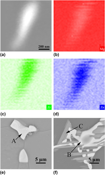
The microstructure of the as-quenched alloys after solution treatment is shown in Fig. 4. In the 0Zn alloys [Figs. 4(a) and 4(b)], there are no longer surviving eutectics. Cuboid-shaped phases with 1 μm or which are less in size can be observed at or near grain boundaries, demonstrating that they are thermal stable during solution treatment at 525 °C. According to the previous study, cuboid-shaped particles determined to be Mg2Y phases can be observed in the as-cast alloy. Reference Rzychon and Kielbus32 Solution treatment made the size and quantity of the cuboid-shaped phase to further increase. Reference Liu, Wu, Liu, Pang and Ding33 Thus, the cuboid-shaped phase originates both from casting and solution treatment processes. Its influence on mechanical properties of the alloy is unknown yet but probably harmful for its huge size and cuboid shape when compared with the precipitate arising from age treatment. There are a significant fraction of colonies of rod-like particles in Zn-containing alloys. With increasing the Zn content, the amount of particles increases. The backscattered SEM image and corresponding EDS results of the rod-like particle are shown in Figs. 5(a)–5(d). According to the EDS results, the rod-like phase is rich in Zr and Zn. There are many studies focusing on rod-like Zr- and Zn-riched intermetallic phases in Mg alloys containing both Zr and Zn. Gao et al. Reference Gao, Muddle and Nie34 characterized the rod-shaped Zr–Zn particles with a tetragonal crystal structure similar to that of Zn2Zr3 phases (P42/mnm, a = 0.768 nm, c = 0.699 nm) in the Mg–1Ca–1Zn–1Zr (wt%) alloy after solution treatment at 480 °C. Sha et al. Reference Sha, Zhu, Liu, Luo, Liu and Ringer35 found that Zr–Zn intermetallic rods in the Mg–6Zn–0.6Zr–0.5Cu (wt%) alloy were Zn3(Zr1−x , Mg x )2 rather than Zn2Zr3 phases.
Microstructure of the as-quenched alloys produced by metallic and sand mold casting: (a) and (b) 0Zn; (c) and (d) 0.2Zn; (e) and (f) 0.5Zn; (g) and (h) 1.0Zn alloys. The insets in the optical metallographic photographs are typical SEM microstructure.

Backscattered SEM image (a) and corresponding EDS results of the Zr- and Zn-riched rod-like particle in the as-quenched metallic mold casting 1.0Zn alloy; (b) Mg map; (c) Zr map; (d) Zn map; residual eutectics and planar features in the as-quenched 1.0Zn alloys; (e) metallic mold casting; and (f) sand mold casting.

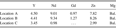
Some eutectics at triple grain boundaries, however, remain undissolved in the as-quenched 1.0Zn alloys. It seems that the solution of Zn reduces the solid solubility of RE. Comparing the microstructure of the sand mold casting alloy with that of the metallic mold casting alloy [Figs. 5(e) and 5(f)], the lager-sized undissolved eutectics together with planar features interspersed among eutectics are observed. The metallic mold casting 1.0Zn alloy has an average grain size of ∼55 μm and the sand mold casting one ∼70 μm, about 15 μm larger than that of as-cast alloys. In addition, average grain sizes of 1.0Zn alloys are much smaller than those of 0Zn, 0.2Zn, and 0.5Zn alloys (∼75 μm for metallic mold casting alloys and ∼85 μm for sand mold casting alloys), suggesting a good thermal stability of grains. Residual second eutectics, the area fractions of which in the OM of metallic and sand mold casting alloys are 1.0% and 2.4%, respectively, act as effective obstacles to grain boundary migration at 525 °C. EDS results of typical locations in Fig. 5 are listed in Table III. Residual eutectics in the metallic and sand mold casting alloys are rich in Nd, Zn, Y, and Gd, similarly. The planar feature is enriched in Y, Zn, and Nd. A similar finding was obtained in Mg–Y–Zn alloys Reference Zhu, Morton and Nie2,Reference Zhu, Morton and Nie27,Reference Zhu, Morton, Weyland and Nie36 such that the planar feature was determined to be a 14H precipitate phase, which is associated with Shockley partial dislocations forming during solution treatment. The 18R LPSO structure in as-cast alloy was not thermodynamically stable and was gradually replaced by the 14H LPSO structure during solution treatment. Reference Zhu, Morton and Nie2,Reference Zhu, Morton and Nie27
EDS results of the micro zones in Fig. 5 (at.%).

Tensile properties of the as-quenched alloys are shown in Fig. 6. YS and UTS of the Zn-containing alloys are higher than those of the Zn-free alloys. With raises in the Zn content, YS and UTS increase monotonously. YS and UTS of the metallic mold casting 1.0Zn alloy are 17 and 43 MPa, higher than those of the 0Zn alloy, and for the sand mold casting alloy, the figures are 14 and 31 MPa, respectively. The incensement of strength and hardness (Fig. 7) in the Zn-containing as-quenched alloys is attributed to the increased concentration of solute atoms (Zn) in the α-Mg matrix. Whether the Zr- and Zn-riched particles have a strengthening effect on the studied alloys is unclear. Atiya et al. Reference Atiya, Bamberger and Katsman37 suggested that rod-like Zn2Zr3 particles served as additional nucleation sites for the Mg–Nd precipitates and affected the kinetics of the precipitation sequence in the Mg–3.1Nd–0.25Zn–0.45Zr (wt%) alloy.
Tensile properties of the as-quenched alloys: (a) YS; (b) UTS; and (c) EL.

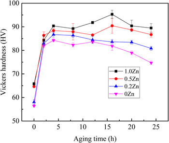
Hardening curves of the metallic mold casting alloys isothermally aged at 225 °C for various hours.

EL is greatly enhanced after solution treatment, and the metallic mold casting alloys show much higher EL. Similar to as-cast alloys, the EL of as-quenched 0.5Zn alloys is higher than that of 0.2Zn alloys but decreases when raising the Zn content from 0.5 to 1.0%. The finer grains and undissolved eutectic compounds in 1.0Zn alloys are responsible for such trend. The average grain sizes of 1.0Zn alloys are 15–20 μm smaller when compared with those of 0.5Zn alloys. However, the surviving eutectics at grain boundaries will very likely act as the sources of crack through their weakening influence on mutual connection between grains and thus make the alloys own a relatively poor ductility.
C. Age hardening behaviors
Age hardening curves of the alloys isothermally aged at 225 °C for different hours are shown in Fig. 7. All the alloys exhibit rapid age hardening in the first 2 h. The curves of 0Zn and 0.2Zn alloys reach their peaks at 4 h with a maximum hardness of 84.3 and 86.7 HV, respectively. The time to get peaked for 0.5Zn and 1.0Zn alloys is delayed to 16 h, and their peak hardness is 90.4 and 95.3 HV. It has been well studied that globular- or ellipsoidal-shaped β′ precipitates during age treatment at 225 °C are the most effective in strengthening and hardening the Mg–Y–Nd–Gd(–Zn) alloy. Reference Liu, Gao, Liu, Zhu, Wang and Nie38,Reference Liu, Wu, Liu, Pang and Ding39 Additionally, it was suggested that Zn was not stable in the supersaturated solid solution. By annealed at 300, 400, and 500 °C, SFs, thin bands of the 14H LPSO structure and relatively thick bands of the LPSO structure precipitated in the α-Mg crystalline grains of an Mg–Y–Nd alloy. Reference Lee, Sato, Konno and Hiraga40 The SFs and LPSO structure were stabilized by the segregation of Zn and Y/Gd from a supersaturated solid solution.
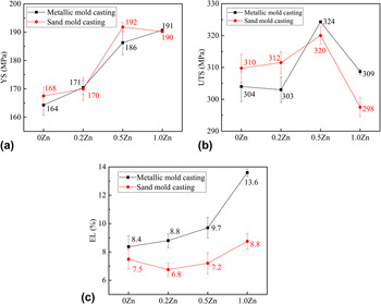
Tensile properties of the peak-aged alloys are displayed in Fig. 8. YS and UTS of the alloys are enhanced accompanied by a significant decrease of EL after age treatment. YS changes in accordance with hardness such that YS or hardness increases with increasing the Zn content. The alloys exhibit an increasing age hardening response when adding Zn from none to 0.5%. YS of 0.5Zn alloys is 22 and 24 MPa higher, and UTS is 20 and 10 MPa higher than those of the 0Zn alloys processed by metallic and sand mold casting, respectively. For 1.0Zn alloys, UTS is 15 and 22 MPa lower than that of 0.5Zn alloys. By contrast, EL increases by 3.9 and 1.6% numerically. The undissolved eutectics make the supersaturated solid solution of α-Mg have a lower content of RE. The amount of precipitates after age treatment is reduced. The work-hardening capacity is weakened, consequently, just as the WE43 alloy shows lower strength and creep resistance than that of the WE54 alloy. Reference Mordike41 The fine grain of 1.0Zn alloys, as a result of obstructive effect of residual eutectics on grain growth during solution treatment, is the critical factor making the alloys exhibit good ductility. It is notable that UTS of the metallic mold casting 1.0Zn alloy is 11 MPa higher than that of the sand mold casting 1.0Zn alloy. It can be interpreted as a result of less residual eutectics and finer grains. But the difference of UTS between the two 0.5Zn alloys is much smaller, and sand mold casting 0Zn and 0.2Zn alloys even show a higher UTS though with lager grain sizes. Hence, higher UTS of the metallic mold casting 1.0Zn alloy mainly lies in the contribution of more precipitates or less residual eutectics. The metallic mold casting alloys show obviously higher EL than sand mold casting alloys, and the gap increases with the increase of Zn content. It can be concluded that strength of the alloys is not so strongly linked to the grain size as EL.
Tensile properties of the peak-aged alloys: (a) YS; (b) UTS; and (c) EL.

IV. CONCLUSIONS
Mg–3.0Y–2.5Nd–1.0Gd–xZn–0.5Zr (x = 0, 0.2, 0.5, and 1.0) alloys were prepared by metallic and sand mold casting in this work to investigate the effect of Zn content and cooling rate during solidification on microstructure and mechanical properties of the alloys. Alloys in as-cast, as-quenched, and 225 °C peak-aged three different conditions were studied in a comparative way. Conclusions are reached as follows:
-
(1) As-cast Zn-free alloys mainly consist of α-Mg and eutectics, yet the Zn-containing alloys contain additional LPSO structures within grains. With the increase of Zn content, eutectics get coarser and the area fraction of the LPSO structure increases.
-
(2) Greater cooling rate during solidification brought by metallic mold casting results in the refined grains and eutectics as well as a decrease of the area fraction of the LPSO structure, which enhances the EL of the alloys.
-
(3) Residual eutectics are found in Mg–3.0Y–2.5Nd–1.0Gd–1.0Zn–0.5Zr alloys after solution treatment. Meanwhile, average grain sizes of Mg–3.0Y–2.5Nd–1.0Gd–1.0Zn–0.5Zr alloys are 15–20 μm smaller than those of the other alloys for the pining effect of residual eutectics on grain boundary migration. Hence EL of the alloys is enhanced.
-
(4) The addition of Zn brings a notable enhancement to mechanical properties of the alloys. Taking both strength and ductility into consideration, the peak-aged Mg–3.0Y–2.5Nd–1.0Gd–0.5Zn–0.5Zr alloys perform the highest tensile properties, when YS, UTS, and EL are 186 MPa, 324 MPa, and 9.7% for metallic the mold casting alloy and 192 MPa, 320 MPa, and 7.2% for the sand mold casting alloy.
Supplementary Material
To view supplementary material for this article, please visit https://doi.org/10.1557/jmr.2017.302.
ACKNOWLEDGMENTS
This work is supported by National Key Research and Development Program of China (No. 2016YFB0301003); Shanghai Yang-fan Program (No. 14YF1402000), National Natural Science Foundation of China (No. 51404153); Research Program of Joint Research Center of Advanced Spaceflight Technologies (No. USCAST2015-25); and Science Innovation Foundation of Shanghai Academy of Spaceflight Technology (Nos. SAST2015047 and SAST2016048).