I. INTRODUCTION
Carbon nanocoils (CNCs) are carbon nanofibers (CNFs) with a helical shape; typical fiber and coil diameters in CNCs are 120–400 nm and 400–1000 nm, respectively. Reference Motojima, Kawaguchi, Nozaki and Iwanaga1–Reference Hayashida, Pan and Nakayama3 There are two types of CNCs: the first type, called CNCs, have an inner diameter; the second type does not have an inner diameter, and these are called carbon nanotwists (CNTws). Reference Katsumata, Fujimura, Nagayama, Tabata, Takikawa, Hibi, Sakakibara and Itoh4 It is expected that CNCs will find applications as magnetic absorbing materials, Reference Wang, Gao, Tang, Chen, Duan, Zhao, Lin, Feng, Zhou and Qin5 catalyst supports for fuel cells, Reference Reddy, Jafri, Jha, Ramaprabhu and Ajayan6 active materials for supercapacitors, Reference Barranco, Celorrio, Lazaro and Rojo7 and nanosprings. Reference Qin, Kim, Zhang, Lee, Yang, Pan, Mathwig, Alexe, Gösele and Knez8
We have studied the synthesis of CNCs using Sn/Fe catalysts. Reference Yokota, Shinohara, Kawabata, Takimoto, Suda, Oke, Takikawa, Fujimura, Yamaura, Itoh, Ue and Morioki9 Our laboratory has developed an automatic chemical vapor deposition (CVD) system with a consecutive substrate transfer mechanism; this system can be used to produce 2–3 g of helical CNFs on a catalyst-supported graphite substrate within an hour, using C2H2 feedstock. However, the problem of low CNC purity remains. The major problem in CNC synthesis is that although CNCs can be grown with high purity on the surface of the carbon deposit, a middle layer in which the CNC purity is very low exists inside the carbon deposit. Reference Yokota, Shinohara, Kawabata, Takimoto, Suda, Oke, Takikawa, Fujimura, Yamaura, Itoh, Ue and Morioki9–Reference Hirahara and Nakayama11 Binary alloy catalysts are crucial for the formation of the helical structure. It has been found that Fe is crucial in the formation of carbon tubules, and that neither CNCs nor carbon fibers can be grown using only In2O3 or SnO2. Reference Li and Pan10 Various experimental methods have been proposed for the production of high-purity CNCs. Chang et al. coated a thin Sn film on a 304 SUS substrate from a (C2H3O2)2Sn catalyst precursor to synthesize CNCs with a purity of 80%. Reference Chang and Chang12 Bi et al. used a Co–P catalyst that was formed on a graphite substrate to synthesize CNCs with a purity of 76% from a C2H2/C4H4S feedstock. Reference Bi, Kou, Ostrikov and Wang13 Qi et al. synthesized CNCs with a purity of 93% at a low temperature of 450 °C from a C2H2 feedstock. Reference Qi, Zhong, Deng, Au and Du14 Li et al. used Fe2(SO4)3/SnCl2 as a catalyst precursor to synthesize CNCs with a purity of 90%. Reference Li, Pan, Qian and Liu15 The CNC purity in these reports was evaluated by observing the surface of the carbon deposit. The variations in the CNC purity inside carbon deposits are not yet understood completely.
In this study, we performed experiments in which different catalyst metal vapors were supplied successively in a CVD reactor. The supply of catalysts during the synthesis of CNCs has been reported in only a few previous studies. Reference Wang, Yang, Gaillard, Bandaru and Rao16,Reference Cervantes-Sodi, Vilatela, Jimenez-Rodriguez, Reyes-Gutiérrez, Rosas-Meléndez, Íñiguez-Rábago, Ballesteros-Villarreal, Palacios, Reiband and Terrones17 The synthesized CNCs were analyzed using scanning electron microscopy (SEM) and energy-dispersive x-ray spectroscopy (EDS). X-ray photoelectron spectroscopy (XPS) was used to analyze the catalyst nanoparticles. We carefully analyzed and classified the catalyst nanoparticles embedded in the CNCs, with the aim of understanding the CNC growth mechanism.
II. EXPERIMENTAL
A. Experimental setup
The CVD reactor, which uses a horizontal quartz tube, was the same as that used in our previous studies. Reference Yokota, Shinohara, Kawabata, Takimoto, Suda, Oke, Takikawa, Fujimura, Yamaura, Itoh, Ue and Morioki9 The experiments were performed using the following steps: (i) vacuum-evaporating Sn on the SiO2/Si substrate; (ii) drop coating a Fe2O3 solution on the Sn-coated SiO2/Si substrate, and performing calcination; (iii) mounting the Sn/Fe-coated SiO2/Si substrate in the CVD reactor; (iv) performing CVD using a C2H2/N2 gas mixture; and (v) investigating the effects of changing the catalytic vapor supply, adding tetramethyltin (TMT) and/or ferrocene to the C2H2/N2 gas mixture during CVD.
The CVD reactor is illustrated in Fig. S1. Sn and Fe vapor catalysts were introduced into the CVD reactor using a tube pump and a carburetor. TMT (Sn(CH3)4, purity: >96%, CAS No.: 594-27-4, Tokyo Chemical Industry Co., Ltd., Tokyo, Japan) and ferrocene (Fe(C5H5)2 purity: >95%, CAS No.: 102-54-5, Tokyo Chemical Industry Co., Ltd., Tokyo, Japan) were used as the feedstock for the Sn and Fe catalytic vapors, respectively. These catalytic molecules were mixed in ethanol, fed to a carburetor through a tube pump, and vaporized in the carburetor. The feedstock C2H2 and dilution N2 gases were introduced into the carburetor, and the catalytic vapor was transferred into the quartz tube of the CVD reactor. The catalytic vapor and C2H2 gas were supplied simultaneously.
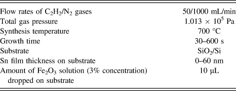
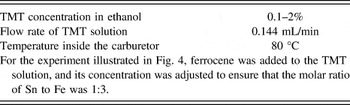
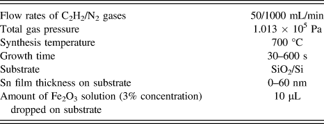
We confirmed that the CNCs grew only from the Sn/Fe catalysts on the substrate; prior to CVD, these catalysts were deposited on the SiO2/Si substrate via the vacuum evaporation of a Sn wire and the drop coating of a Fe2O3 solution, respectively. In this study, we investigated the effects of varying the following experimental conditions: (i) the supply of Sn and/or Fe catalytic vapors to the CVD reactor and (ii) the thickness of Sn thin film deposited on Fe2O3-coated SiO2/Si substrate. The CVD experimental conditions and catalytic vapor supply conditions are listed in Tables I and II.
CVD conditions.
Catalytic vapor supply conditions.

B. Characterization of carbon deposits
The synthesized CNCs and the catalyst nanoparticles were observed using SEM (Hitachi, S-4500II and SU8000, Tokyo, Japan). We evaluated the number density of CNCs on the substrate using the SEM images. The amount of carbon deposited on the substrate was measured using an electronic balance. The elemental composition of the catalyst nanoparticles was analyzed using an energy-dispersive x-ray spectroscopy (EDS) instrument, and the mapping of each element was obtained. XPS (ULVAC-PHI QuanteraII™, Chigasaki, Kanagawa, Japan) was also used for the elemental analysis of the synthesized samples.
In this study, we evaluated the CNC purity, and the number ratio of CNCs to carbon deposits containing CNCs and CNFs, by analyzing the SEM images of (i) the top surface and (ii) the cross-section of the samples. As discussed by Hirahara and Nakayama, CNCs are observed on the surface of the carbon deposits, and carbon-containing catalytic metals and carbon nanotubes can be contained between the substrate and the CNCs. Reference Hirahara and Nakayama11 This result tells us that the CNC purity changes with changes in the height from the substrate. In this study, we solidified the carbon deposit by dropping a Nafion® solution onto it; we then cut the carbon deposit to observe the cross-section. This carbon deposit was transferred into a SEM chamber, and the dependence of the CNC purity on the height from the substrate was analyzed.
III. RESULTS AND DISCUSSION
A. Classification of the catalyst nanoparticles at the CNC tips
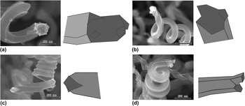
First, we observed the catalyst nanoparticles at the CNC tips. As shown in Fig. 1, almost all the CNCs in the SEM images contained catalyst nanoparticles at their tips. This indicated that the CNCs in this study were grown in a tip-growth mode, in which the catalyst nanoparticles were separated from the substrate. Reference Li, Pan, Liu and Yu18 We chose 100 samples that contained CNCs and CNTws, and investigated their catalyst nanoparticles carefully. The samples were characterized by determining the following properties: (i) the geometry of the catalyst nanoparticle in the CNC; (ii) whether the CNC had left- or right-handed helicity; (iii) the surface geometry of the CNC; and (iv) the inner diameter of the CNC. To briefly summarize the results, it was found that (i) there were four types of catalyst nanoparticles in the CNC tips (Fig. 1); (ii) the ratio of the CNC left- and right-handed helixes was 1:1; (iii) there were two types of CNC surface geometries (angular and round); and (iv) there were two types of CNC inner diameters (CNC and CNTw). These results are described in the Supplementary Material.
SEM images and illustrations of catalyst nanoparticles in CNC tips: (a) Catalyst nanoparticle A (symmetric structure), (b) B (asymmetric structure), (c) C (mirror-symmetric structure with two active facets), and (d) D (branched structure). Neither TMT nor ferrocene was used. The Sn film thickness and growth time were 40 nm and 600 s, respectively. The other growth conditions were the same as those described in Table I. The scale bar represents 500 nm. (Also see Supplementary Material.)

Li et al. reported very similar results, Reference Li, Pan, Liu and Yu18 and concluded that all the catalyst nanoparticles embedded in the CNCs were polyhedral, the majority of them being hexahedrons, and that there was only one catalyst nanoparticle in one CNC. However, our observations demonstrated the existence of a type of catalyst nanoparticle different from those reported by Li et al. In this new particle type, one end of the particle was separated into two branches, whereas the other end (which was in contact with the CNC) was not branched, as shown in Fig. 1(d). Particles of this type were named as branched catalyst nanoparticles. Most of the CNCs synthesized in this study were composed of plural thinner helical CNFs, and their surfaces were angulated. Reference Yokota, Shinohara, Kawabata, Takimoto, Suda, Oke, Takikawa, Fujimura, Yamaura, Itoh, Ue and Morioki9 CNCs containing branched catalyst nanoparticles had more vertices than CNCs containing other types of catalyst nanoparticles, and their surface geometry was almost circular. Note that the same type of CNC surface geometry was obtained from the four types of catalyst nanoparticles. For examples of this, see the Supplementary Material Fig. S2. This suggested that the CNC surface geometry—which depended on the number of thinner helical CNFs, and their thickness—was not determined only by the geometry of the catalyst nanoparticles. This led to the understanding that the differences between the sizes and activities of each active facet in the catalyst nanoparticle were correlated with the interaction among the plural thinner CNFs, and that the CNC surface geometry and CNC coil pitch were determined by these differences.
From the above results, it was understood that the catalyst nanoparticles in the CNCs were always exposed to C2H2/N2 gas molecules during the CVD process, because they were embedded in the CNC tips and were separated from the substrate. In the next section, we describe the results of experiments in which the catalytic vapor supply was varied.
B. Results for CVD with varying catalytic vapor supply
1. Sn deposition on substrates by a TMT supply
Prior to the CVD experiments, we tested the introduction of the TMT vapor into the CVD reactor alone, using a N2 dilution gas. The TMT concentration in ethanol was 1%, the flow rate of the TMT solution was 0.144 mL/min, the N2 gas flow rate was 1000 mL/min, the temperature inside the carburetor was 80 °C, the reactor gas pressure was 1.013 × 10⁵ Pa, the temperature in the reactor was 700 °C, and the growth time was 600 s. The SiO2/Si substrates were located at various positions in the reactor. We observed the deposition of Sn in particulate form on the SiO2/Si substrate in the quartz tube in the range from −120 to +120 mm (where the center of the tube was set to be 0 mm). We fixed the location of the SiO2/Si substrate for the CNC synthesis at 0 mm; at this position, the average diameter and number density of the Sn nanoparticles were 22 nm and 90 particles/μm2, respectively. The Sn nanoparticles obtained on the substrate were smaller than the Sn/Fe nanoparticles (with diameters of 100–200 nm), as observed previously for CNCs by Qian et al. Reference Qian, Pan, Li, Yu and Liu19,Reference Li and Pan20
2. Dependence on the TMT concentration
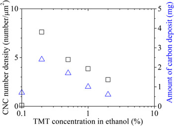
In this growth experiment, the Fe catalysts were formed on the substrate prior to CVD, and the TMT vapor was supplied during CVD. CNCs could be grown under all the TMT concentration conditions (0.1–2% in ethanol) used in this study. We evaluated the CNC number density from the SEM images obtained at each TMT concentration, as shown in Fig. 2.
Dependence of the CNC number density (open squares) and amount of carbon deposits (open triangles) on the TMT concentration in ethanol. No Sn film was deposited on the SiO2/Si substrates. The growth time was 600 s. The other growth conditions were the same as described in Tables I and II.

The CNC number density was highest at a TMT concentration of 0.2%. As the TMT concentration was increased to more than 0.2%, the CNC number density decreased. The amount of carbon deposits showed a similar tendency.
The use of a small amount of Sn promotes the growth of carbon materials when it is used in combination with a Fe catalyst. Reference Pan, Hayashida, Harada and Nakayama21 To investigate this effect, we analyzed CNCs grown at higher TMT concentrations. A number of Sn nanoparticles were attached to the surface of the CNCs that were grown. It was determined that the appropriate TMT concentration in our experiments was below 1%.
3. Use of Sn thin films with a TMT supply
The TMT concentration in ethanol was fixed at 0.2%, and the thickness of the Sn thin film on the substrate was varied. CNCs were grown at all the Sn film thicknesses (0, 20, 40, and 60 nm). Thicknesses of 40 and 60 nm resulted in particularly high-purity CNCs. The CNC purity increased with increasing Sn film thickness, but decreased a little with a Sn film thickness of 60 nm. The CNC purity was highest (≈62%) for a Sn film thickness of 40 nm. When the CNC purity obtained using the combination of Sn thin films and TMT was compared with that obtained using Sn thin films alone, there was almost no difference. Although TMT was supplied, it did not seem to have any influence on the CNC purity.
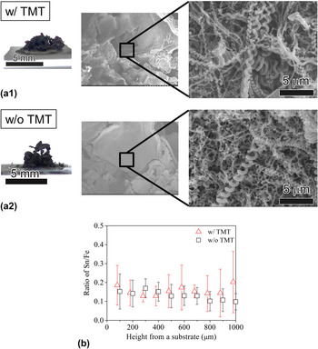
Figure 3(a) shows photographs of the as-grown carbon deposits obtained using a Sn film thickness of 40 nm, and SEM micrographs of their cross-sections. From the SEM observations, the CNC purity inside the carbon deposits was lower than that on its surface, whether TMT was supplied or not. The averaged CNC purities (averaged over the whole carbon deposit) evaluated from the SEM images of the sections of the carbon deposits were 42% with TMT, and 28% without TMT. The CNC purity was increased 1.5-fold by the TMT supply. Sections of the carbon deposit were analyzed using EDS every 100 μm from the substrate surface, up to a height of 1000 μm from the surface, where the density of the carbon deposit was uniform. The molar ratio of Sn to Fe (Sn/Fe ratio) was determined via a quantitative analysis of the EDS spectra of the carbon deposit as shown in Fig. 3(b). The Sn/Fe ratios obtained using TMT were higher than those obtained without TMT. This suggested that the TMT supplied the Sn catalyst to the inside of the carbon deposits as well as the surface of the substrate.
(a) Photographs of the as-grown carbon deposits, and SEM micrographs of their cross-sections: (a1) with and (a2) without TMT. (b) Relationship between the Sn/Fe ratio at the cross-sectional surfaces of the carbon deposits and the height from the substrate. The TMT concentration in ethanol, Sn film thickness, and growth time were 0.2%, 40 nm, and 600 s, respectively. The other growth conditions were the same as described in Tables I and II.

The length of the CNCs grown in this experiment was approximately 50 μm, much smaller than the height of the carbon deposit (≈3 mm). It seems reasonable that the CNCs seen on the surface of the carbon deposit grew from a certain position inside the carbon deposit, which can be assumed to have acted as a “substrate.” Reference Li and Pan10,Reference Hirahara and Nakayama11 This experimental method could supply the catalyst required by the CNCs, regardless of the height from the substrate surface at which the CNCs started to grow.
4. Addition of ferrocene
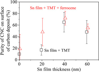
Ferrocene was added to the TMT solution, and the molar ratio of Fe:Sn was set at 3:1 in the solution. Reference Li, Pan, Qian and Liu15 The CNC purities on the surface of the carbon deposit were evaluated for different Sn film thicknesses, as shown in Fig. 4.
Purity of CNCs grown on the surface of carbon deposits under a supply of TMT and ferrocene. The TMT concentration in ethanol and growth time were 0.2% and 600 s, respectively. The other growth conditions were the same as described in Tables I and II.

The results clearly showed that the CNC purity increased under the supply of ferrocene, especially for the Sn film thickness of 20 nm. The highest-purity CNCs—with a value of 72%—were obtained using a Sn film thickness of 40 nm.
In the experiments investigating the addition of ferrocene, it was possible to grow the CNCs in the vapor phase, because the Sn and Fe catalysts were supplied as a vapor. To confirm this, the carbon deposit on the inner wall of the quartz tube was analyzed using SEM. CNCs were not observed, although there were some CNFs. Since ferrocene and TMT could be decomposed at the CVD growth temperature used in this study, Reference Waring and Horton22,Reference Dyagileva, Mar'in, Tsyganova and Razuvaev23 it seems reasonable that CNFs were grown from catalyst nanoparticles in the vapor phase. Li et al., however, argue that it is necessary for the CNC catalyst nanoparticles to be fixed on a substrate to form the CNCs' helical structure. Reference Li and Pan10
C. Observation of the initial CNC growth stage
1. SEM observations
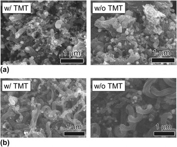
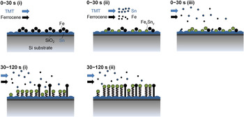
We performed CVD under a TMT supply for short periods of 30 and 120 s, and investigated the effect of varying the catalytic vapor supply on the initial CNC growth stage, in which the nucleation of the catalyst nanoparticles and carbon segregation occurred on the substrate surface. The Sn film thickness was set at 40 nm. Figure 5 shows the SEM images of the initial CNC growth, with and without TMT.
Initial growth of CNCs on the substrate with and without TMT, after synthesis performed for (a) 30 s and (b) 120 s. The TMT concentration in ethanol and the Sn film thickness were 0.2% and 40 nm, respectively. Ferrocene was not added. The other growth conditions were the same as described in Tables I and II.

CNCs were not observed on either of the substrates (with or without TMT) with a growth time of 30 s; instead, small numbers of CNFs were grown from the catalyst nanoparticles. CNC growth was confirmed on both substrates (with and without TMT) with a growth time of 120 s. The CNC purities with and without TMT were determined as 23 and 13%, respectively. This showed that the purity of the CNCs that started to grow on the substrate surface also increased with the supply of TMT.
2. Elemental analysis
The EDS mapping analysis for the samples in Fig. 5 was performed. The area of Fe detection for the samples grown without TMT was larger than that for the samples grown with TMT. In contrast, Sn was rarely detected in the samples grown for 30 s, whether grown with or without TMT. The Sn/Fe ratios were determined to be 0.01 from the mapping analysis.
There were many CNCs and CNFs on the substrate. We now consider the differences between the samples grown with and without TMT. In the case of those grown without TMT, compared with the sample grown for 30 s, the deposition of CNFs and CNCs on the sample grown for 120 s resulted in a decrease in the Fe and Sn contents. The Sn/Fe ratios were the same, 0.01. In contrast, in the case of TMT, more Sn was detected over a wider area on the sample grown for 120 s than on the sample grown for 30 s. The Sn/Fe ratio for the sample grown for 120 s was 0.06, six times larger than that grown for the same period without TMT.
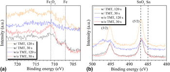
Figure 6 shows XPS spectra for the samples grown for different times, and with and without a TMT supply. The Fe2p and Sn3d intensities for the samples grown without TMT decreased with increasing growth time. In contrast, a strong Sn3d peak, which was assigned to SnO2, was detected for the samples grown for 120 s with TMT. This supported the EDS analysis results.
(a) Fe2p and (b) Sn3d XPS spectra for CNC samples grown for 30 and 120 s.

In this experiment, the Sn catalytic vapor supply affected the Sn supply on the substrate, and produced CNC growth after a growth time of 120 s. However, a 30 s supply of Sn catalytic vapor had very little effect. A model for the CNC growth with a catalytic vapor supply is illustrated in Fig. 7. The addition of TMT enhanced the Sn/Fe nanoparticle nucleation sites for the CNC growth between 30 and 120 s. By supplying TMT during CVD, some Sn nanoparticles could enhance the Sn/Fe nanoparticle nucleation sites for the CNC growth. A suitable amount of Sn/Fe catalysts improved the Sn/Fe ratio in the catalyst nanoparticles on the substrate, and Sn/Fe nanoparticle nucleation sites for the CNC growth could be formed and enhanced.
Model for CNC growth at the initial stage, with a catalyst supply from the vapor phase.

D. Analysis of different CNC surface geometries
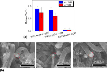
We analyzed individual CNCs in detail using SEM and EDS. Fe and Sn were detected in all of the catalyst nanoparticles in these CNCs and CNFs, with the exception of those in the round-type CNFs. A number of CNCs and CNFs (each of which was grown with or without a TMT supply) were analyzed, and the averaged Sn/Fe ratios are shown with their standard deviations in Fig. 8. The EDS mapping of one Sn/Fe catalyst nanoparticle at angular-type CNC tip, which was grown without TMT, was obtained as shown in Fig. S3. The Sn/Fe ratio of the catalyst nanoparticle was 0.205, close to those of the angular-type CNCs in Fig. 8(a). Note that there was a large difference between the Sn/Fe ratios for the angular- and round-type CNFs, whether they were grown with or without a TMT supply. The observations for the angular-type CNFs indicated that Sn-containing catalyst nanoparticles did not always produce CNCs. When angular-type CNFs and CNCs were compared, it was observed that the surface geometries were similar; they were composed of many thinner CNFs, as described in our previous paper. Reference Yokota, Shinohara, Kawabata, Takimoto, Suda, Oke, Takikawa, Fujimura, Yamaura, Itoh, Ue and Morioki9 These results suggested that the angular structure on the CNF surface was formed via the growth of plural thinner CNFs from each active facet on the catalyst nanoparticle. Motojima and co-workers proposed a two- and three-dimensional growth mechanism for the CNCs based on the anisotropic deposition of carbon on the different crystal planes. If the catalytic activity of one crystal plane of a catalyst nanoparticle is larger than that of the other plane, the resulting fiber will curl, forming a CNC. Reference Motojima and Iwanaga24
(a) Sn/Fe ratios of catalyst nanoparticles in CNCs and CNFs grown with or without a TMT supply. The TMT concentration in ethanol, Sn film thickness, and growth time were 0.2%, 40 nm, and 600 s, respectively. Ferrocene was not added. The other growth conditions were the same as described in Tables I and II. (b) SEM micrographs of a representative angular-type CNC, and angular- and round-type CNFs.

It is interesting that the Sn/Fe ratios for the catalyst nanoparticles in the CNCs decreased when the TMT supply was applied. The reason for this difference is not clear; however, the Sn/Fe ratios for the catalyst nanoparticles obtained with and without TMT were close to the optimal Sn/Fe ratio (≈0.2) obtained by Wang et al. Reference Wang, Yang, Gaillard, Bandaru and Rao16
The surface geometry of the CNTws Reference Katsumata, Fujimura, Nagayama, Tabata, Takikawa, Hibi, Sakakibara and Itoh4 (which did not have an inner diameter) was mainly rounded. In a previous study, we grew CNCs from a Sn/Fe catalyst and CNTws from a Sn/Ni catalyst. Reference Yokota, Shinohara, Kawabata, Takimoto, Suda, Oke, Takikawa, Fujimura, Yamaura, Itoh, Ue and Morioki9 Taking into account the CNTw growth, the formation of an angular structure was not sufficient to ensure the formation of a helical structure. We believe that the factors necessary for the formation of a helical structure (depending on the surface geometry) are as follows: (i) In the case of the angular-type CNCs, which are composed of plural thinner CNFs, a difference in the speed of segregation of the thinner CNFs from the catalyst nanoparticle is necessary. Reference Li and Pan20 (ii) In the case of the round-type CNTws, which are formed from one CNF, a deviation on the active facet from which the CNF starts to grow is necessary.
IV. SUMMARY
In this study, we proposed a method to supply a Sn/Fe catalyst with a CVD feedstock gas for the growth of CNCs from a vapor phase, and grew CNCs. The results obtained in this study were as follows:
-
(1) There were four types of catalyst nanoparticles in the CNC tips. Catalyst nanoparticles with a branched structure were observed.
-
(2) The CNC purities evaluated from the SEM images of the sections of the whole carbon deposits were 42% with TMT, and 28% without TMT. The CNC purity was increased 1.5-fold by the TMT supply.
-
(3) Under the supply of ferrocene and TMT, the highest CNC purity of 72% (which was evaluated via the observation of the surface of the carbon deposits) was obtained using a Sn film thickness of 40 nm.
-
(4) The Sn catalytic vapor supply affected the Sn supply on the substrate, and produced CNC growth after a growth time of 120 s.
-
(5) There was a large difference between the Sn/Fe ratios of the catalyst nanoparticles embedded in the angular- and round-type CNFs, indicating that Sn-containing catalyst nanoparticles did not always produce CNCs.
It was shown that the method proposed in this study was effective in producing CNCs that started to grow far from the substrate surface, and that this method thus holds advantages for the high-quantity synthesis of CNCs.
Supplementary Material
To view supplementary material for this article, please visit http://dx.doi.org/jmr.2014.247
ACKNOWLEDGMENTS
This work was partly supported by the EIIRIS Project from Toyohashi University of Technology (TUT); the Core University Programs (JSPS-CAS program in the field of “Plasma and Nuclear Fusion”) from the Japan Society for the Promotion of Science (JSPS); JSPS KAKENHI Grant Nos. 24360108 and 25630110; and Ministry of Education, Culture, Sports, Science and Technology KAKENHI Grant No. 24110708.