I. INTRODUCTION
Since the unlicensed use of 3.1–10.6 GHz for ultra-wideband (UWB) communications in 2002 was authorized by Federal Communications Commission (FCC) [1]. The UWB technology began to receive widespread attention, as it is seen as one of the key technology in the future wireless communication. As one of the essential modules in the UWB communication systems, UWB bandpass filters play an important role in the overall performance of the system. Generally speaking, good in-band transmission, out-of-band rejection, and flat group delay are asked for UWB filters in practical application.
So far, various UWB bandpass filters have been developed. One efficient approach to develop an UWB bandpass filter is to construct a multi-mode resonator (MMR) and then design an UWB bandpass filter on it. For example, an UWB bandpass filter based on an MMR that consists of one half-wavelength low-impedance line section in the center and two identical high-impedance line sections at the two sides, is proposed in [Reference Zhu, Sun and Menzel2]. [Reference Zhu and Chu3] proposes an UWB bandpass filter based on a dual-stub-loaded resonator that consists of a traditional stepped impedance resonator with two pairs of stubs tapped-connected. In [Reference Deng, Zhao, Zhang, Zhang and Gao4], an UWB bandpass filter based on a microstrip quintuple-mode stub-loaded resonator is discussed. [Reference Chu, Wu and Tian5] introduces an UWB bandpass filter based on an MMR that is constructed by loading three open stubs in a uniform-impedance resonator. An UWB bandpass filter based on an MMR that is constructed by cascading interdigital coupled microstrip line sections with short-ended stepped impedance stubs being loaded is analyzed in [Reference Zhang and Xiao6]. Li and Ji [Reference Li and Ji7] describe an UWB bandpass filter with cross-coupling between λ/4 short-circuited stubs, but its performance in the upper stopband is not good. In [Reference Wang, Zheng, Kang, Miao and Wu8], an UWB bandpass filter is presented whose return loss in the passband is only −7 dB. Therefore, great effort is still needed for the development of novel UWB bandpass filters with better performance and more compact size to meet actual requirement.
In this paper, a novel MMR is proposed by cascading several open-circuited transmission line sections with a coupled-line section. Based on it, an UWB bandpass filter is designed, which shows good performance.
II. NOVEL MMR AND ITS APPLICATION IN UWB BANDPASS FILTER
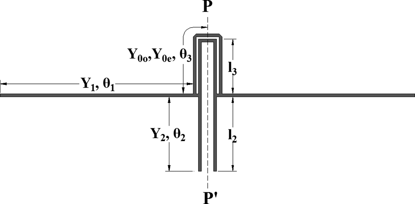
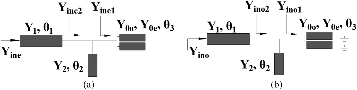
The schematic of the proposed MMR is shown in Fig. 1, in which several open-circuited transmission line sections are connected with a coupled-line section. Owing to its symmetry, odd- and even-mode analysis methods can be applied to analyze the resonance characteristic of this resonator. The odd- and even-mode equivalent models are presented in Fig. 2. As for the even-mode equivalent model, its input admittance can be derived as
 $${Y_{ine1}} = 2{Y_{11}} + 2{Y_{13}} + 2K({Y_{12}} + {Y_{14}}),$$
 $$K = \displaystyle{{{Y_{13}}{Y_{14}} - {Y_{11}}{Y_{14}}} \over {Y_{11}^2 - Y_{13}^2}},$$
 $${Y_{11}} = - j\displaystyle{1 \over 2}({Y_{0o}} + {Y_{0e}})\cot {\theta _3},$$
 $${Y_{12}} = - j\displaystyle{1 \over 2}({Y_{0o}} + {Y_{0e}})\csc {\theta _3},$$
 $${Y_{13}} = - j\displaystyle{1 \over 2}({Y_{0o}} - {Y_{0e}})\cot {\theta _3},$$
 $${Y_{14}} = - j\displaystyle{1 \over 2}({Y_{0o}} - {Y_{0e}})\csc {\theta _3},$$
Then,
 $${Y_{ine2}} = {Y_{ine1}} + j{Y_2}\tan {\theta _2}.$$
Finally,
 $${Y_{ine}} = {Y_1}\displaystyle{{{Y_{ine2}} + j{Y_1}\tan {\theta _1}} \over {{Y_1} + j{Y_{ine2}}\tan {\theta _1}}}.$$
Let Y ine = 0 to determine the even-mode resonance condition. As for the odd-mode equivalent model, its input admittance can be derived as
 $${Y_{ino1}} = 2{Y_{22}} + 2{Y_{13}},$$
 $${Y_{ino2}} = {Y_{ino1}} + j{Y_2}\tan {\theta _2}.$$
Finally,
 $${Y_{ino}} = {Y_1}\displaystyle{{{Y_{ino2}} + j{Y_1}\tan {\theta _1}} \over {{Y_1} + j{Y_{ino2}}\tan {\theta _1}}}.$$
Let Y ino = 0 to have the odd-mode resonance condition determined.
Proposed MMR.

Even- and odd-mode equivalent models of the MMR. (a) Even-mode equivalent model. (b) Odd-mode equivalent model.

The calculated and simulated results are presented in Table 1. The first odd mode is denoted as f o1, the second odd mode as f o2, and the first even mode as f e1. The calculated and simulated results coincide approximately. The difference owes to the simplification in our calculation, for example, neglect of dispersion effect, coupling effect and other effects. The odd- and even-mode resonance conditions can help to choose initial dimensions to appropriately allocate these resonant frequencies.
Comparison between the calculated resonance frequencies with the simulated ones.

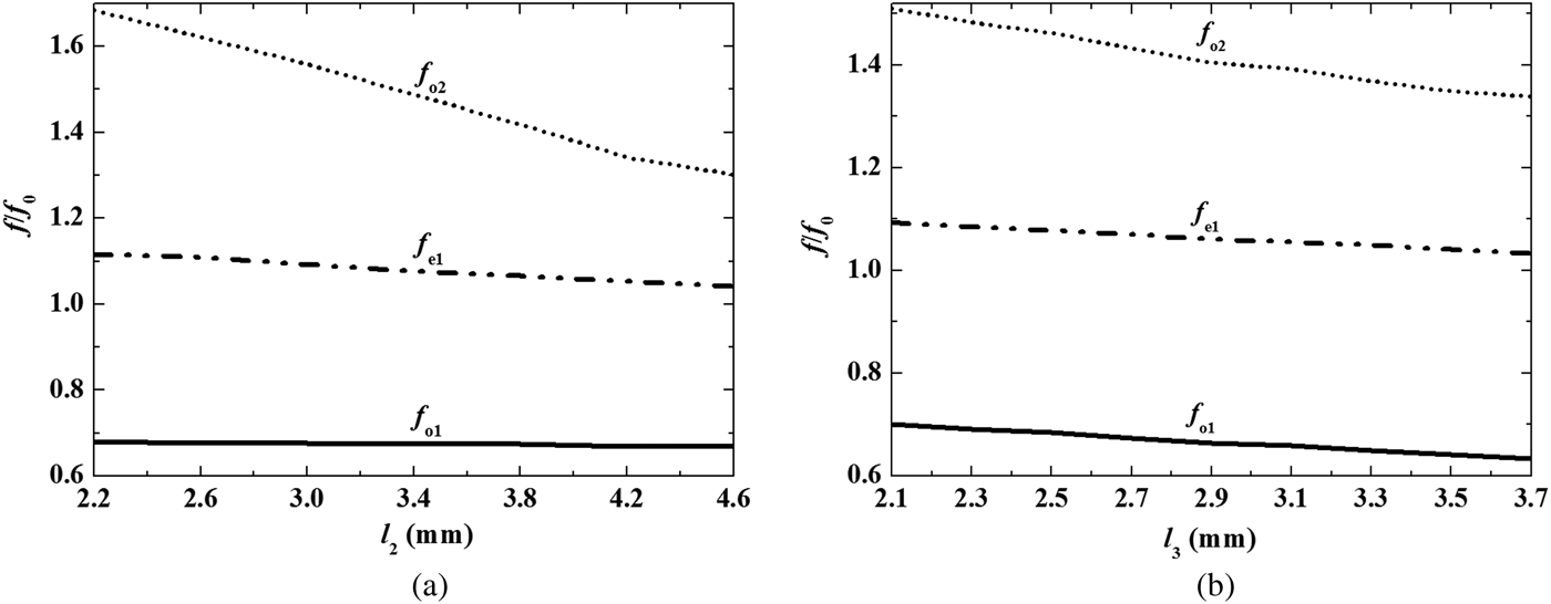
To further investigate the effect of some structural parameters on the resonance characteristic of the resonator, the variation of resonant frequencies versus the length l 2 and l 3 are depicted in Fig. 3, respectively. In Fig. 3(a), as the length l 2 of the open stubs increase, f o1 is almost unaffected, f e1 is slightly decreased, and f o2 will be greatly shifted downward. Thus, f o2 can be controlled in wide frequency range by adjusting the length l 2 of the open stubs. In Fig. 3(b), these three resonant frequencies will be affected by changing the length l 3 of the coupled-line sections. As l 3 increases, all three resonant frequencies will decrease. In practice, we can move these resonant frequencies to wherever they are desired to meet actual requirement.
Effect of some structural parameters on the variation of resonant frequencies scaled by f 0 = 6.85 GHz. (a) Resonant frequencies versus the length l 2 (other parameters are: g 2 = 0.12 mm, l 3 = 2.72 mm, and l 4 = 0.6 mm, respectively). (b) Resonant frequencies versus the length l 3 (other parameters are: g 2 = 0.12, l 2 = 3.7, and l 4 = 0.6 mm, respectively).

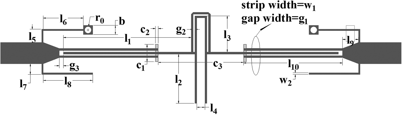
Based on this MMR, an UWB bandpass filter can be designed. Rogers RT/duroid 5880 substrate with a relative permittivity of 2.2 and a dielectric height of 0.508 mm is used here. To cover the desired UWB bandwidth of [3.1, 10.6] GHz, initial dimensions of the resonator are chosen to appropriately allocate three resonant frequencies are according to the resonance conditions derived by both odd- and even-mode analysis methods. Then, 50 Ω feedlines are coupled to the resonator as shown in Fig. 4.
Schematic representation of the proposed UWB bandpass filter.

To strengthen coupling between the feedlines and the resonators, some defected ground structures (DGSs) are etched at the back of the filter. In this filter, two rectangular DGSs are etched, as shown in Fig. 4. As the simulation verifies, they can widen the passband of the filter to some extent. The dimensions of the air boxes beneath two rectangular DGSs are 7 × 2 × 2 mm3, respectively.
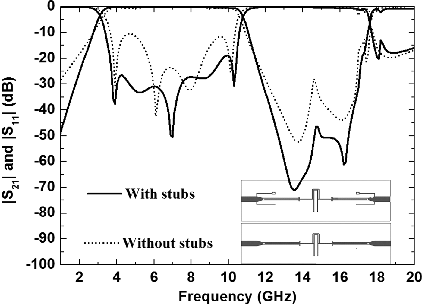
To further improve the performance of the filter, some matching stubs are added at input/output ports for impedance matching. The filters with or without the matching stubs are simulated to demonstrate their effect. In Fig. 5, the simulated results of the filters with or without the matching stubs are presented. As can be seen, UWB frequency response can be achieved even without the matching stubs. However, its selectivity is not so good and the return loss in the passband is unsatisfactory. Through the introduction of these matching stubs, the performance of the filter can be improved. In the first place, the return loss in the whole passband can be reduced greatly. Secondly, the selectivity of the filter is improved due to the transmission zeros created by the matching stubs at the both sides of the passband [Reference Wang, Zheng, Kang, Miao and Wu8].
Effect of the matching stubs at input/output ports on the performance of the filter.

III. MEASUREMENT AND DISCUSSION
To verify the discussion in the previous section, a filter is eventually fabricated and measured according to Fig. 4. The structural parameters in Fig. 4 are set as: l 1 = 9.58, l 2 = 3.7, l 3 = 2.72, l 4 = 0.6, l 5 = 1.0, l 6 = 3.0, l 7 = 1.0, l 8 = 3.0, l 9 = 1.2, l 10 = 7.4, w 1 = 0.15, w 2 = 0.12, g 1 = 0.12, g 2 = 0.12, g 3 = 0.3, c 1 = 1.3, c 2 = 0.2, c 3 = 6.4, b = 0.7, and r 0 = 0.25 mm. The whole size of the fabricated filter is about 0.75λ g × 0.22λ g , where λ g is the guided wavelength at 6.85 GHz. The photograph of the fabricated filter is shown in Fig. 6.
Photograph of the fabricated filter.

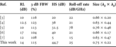
In Fig. 7, the simulated and measured results of the fabricated filter are presented. The measured 3 dB passband can cover from 2.92 to 10.8 GHz, i.e. 115% fractional bandwidth (FBW). The measured insertion loss including the loss due to a pair of SubMiniature version A (SMA) connectors is about 0.9 dB at 6.85 GHz. The return loss in the whole passband is better than −14 dB. The filter is featured by good performance in stopband. As low as −40 dB suppression can be achieved within frequency range from 12.0 to 16.0 GHz. Even in frequency range from 16.0 to 20.0 GHz, at least −12 dB suppression can be achieved. The simulated and measured group delay is shown in Fig. 7(b). It's relatively flat in the whole passband and the variation is between 0.6 and 0.8 ns. To clearly demonstrate the advantages of the proposed filter, it is compared with other UWB bandpass filters in some well-known literatures, as shown in Table 2. The comparison shows that the performance of the filter is good, while its size is comparable with the others’.
Simulated and measured results of the fabricated filter. (a) S-parameters. (b) Group delay.

Comparison between the proposed UWB bandpass filter and other filters.
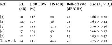
RL: return loss; 3 dB FBW: 3 dB fractional bandwidth; HS: harmonic suppression up to 15 GHz; Roll-off rate: |α max − α min|/|f s − f c | where α max is 30 dB attenuation, α min is 3 dB attenuation, f s is the frequency point corresponding to 30 dB attenuation and f c is the frequency point corresponding to 3 dB attenuation; λ g is the guided wavelength at 6.85 GHz.
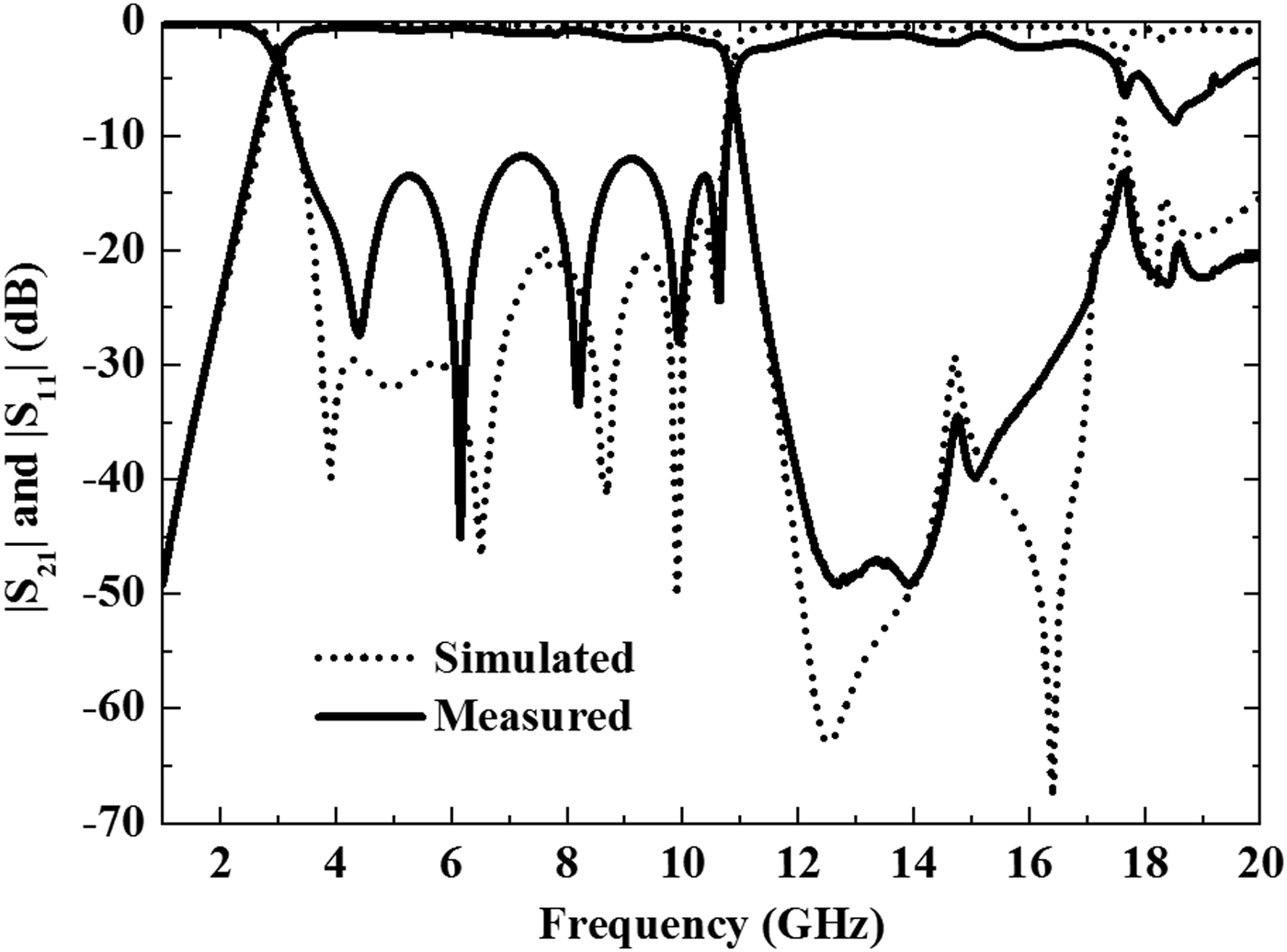
In practice, selectivity of the filter could be improved further by adjusting the length of the matching stubs. For example, the second filter with l 7 = 0.8 and l 8 = 3.7 mm is fabricated and measured, while other structural parameters are kept unchanged. The simulated and measured results are depicted in Fig. 8. The 3 dB passband covers [2.97, 10.76] GHz, i.e. 113% FBW. Its roll-off rate could reach as high as 36.
Simulated and measured frequency responses of the fabricated filter with sharper selectivity.

IV. CONCLUSION
In this paper, a novel MMR is discussed and its resonance characteristic is analyzed through even- and odd-mode analysis methods. Based on it, a compact UWB bandpass filter is designed. By adding the short- and open-circuited stubs at input/output ports for impedance matching, the performance of the filter can be improved further. The measurement of the fabricated filter shows that the filter is featured by good selectivity and wide stopband.
ACKNOWLEDGEMENT
The authors would like thank Editors and Reviewers for their work and help.
 Ting Zhang is pursuing M.S. degree in the University of Electronic Science and Technology of China (UESTC).
 Fei Xiao received the B.S. degree in Applied Physics from ChongQing University in 1997, the M.S. degree in Physical Electron and the Ph.D. degree in Radio Physics from the University of Electronic Science and Technology of China (UESTC) in 2002 and 2005, respectively. From 2009 to 2010, he was a visiting researcher to the Royal Institute of Technology, Sweden. Now, he is currently an Associate Professor in UESTC. Up to now, he has authored more than 60 journal and conference papers. His research interests include filter synthesis, microwave passive components design, computational electromagnetics, etc.
 Xiaohong Tang received B.S. and Ph.D. degrees in Electromagnetism and Microwave Technology in UESTC. Now he is a Professor in UESTC. He has authored more than 100 journal and conference papers. He was also the recipient of several national and provincial awards. His research interests include microwave and millimeter communication, computational electromagnetics, etc.
 Lei Guo is a Lecturer in UESTC. His research interests include single processing.