I. INTRODUCTION
Natural and engineered multilayer structures can exhibit intriguing properties and functionalities. Reference Cahn1 As an example, lamellar structures (α ferrite/Fe3C cementite) on the microscopic scale are the foundation for the combination of strength and toughness of steels. Some structures in nature, such as mollusk shells, derive their high strength and toughness from ceramic layers bonded together by an organic glue. Reference Laraia and Heuer2 Multilayer thin films may now actually be viewed as a new class of materials. With a thickness of up to tens of micrometers and layer thicknesses of a few to hundreds of nanometers, these structures have a wide range of applications including optical devices, high-performance capacitors, ultrahigh-strength materials, thermo-electric materials, high wear resistance and low friction coatings for gears, bearings, cutting tools, and thermal protective layers in aircraft and automobile engines. Reference Ko, Dechakupt, Randall, Trolier-McKinstry, Randall and Tajuddin3–Reference Schmitt, Rai, Bhattacharya, Zhu and Wolfe8 In addition, certain systems, such as the aluminum (Al)-silicon carbide (SiC) nanolayers, are being considered as reflective coatings in ultraviolet applications as well as other applications. Reference Windt and Bellotti9–Reference Lotfian, Rodriguez, Yazzie, Chawla, Llorca and Molina-Aldareguia11,Reference Ziani, Delmotte, Le Paven-Thivet, Meltchakov, Jerome, Roulliay, Bridou and Gasc10 Compared to traditional material systems, these materials can offer higher strength to weight ratios, less friction and wear, higher operation temperatures, corrosion resistance, and fracture toughness. Therefore, designing and manufacturing multilayered structures at the micro- and nanoscales are attractive strategy for developing a new generation of protective and infrastructure materials, and thus have been subjects of intensive research. Reference Knorr, Cordero, Lilleodden and Volkert12–Reference Budiman, Han, Li, Wei, Dickerson, Tamura, Kunz and Misra18
The scale and complexity of these multilayered structures often make it difficult to characterize mechanical behavior. Nanoindentation is a commonly used experimental technique to determine the composite hardness and elastic modulus. The hardness can be derived directly from the peak indentation load and projected contact area. On the other hand, the indentation-derived elastic modulus is determined from the projected contact area and the contact stiffness at the onset of unloading. Various experimental and analytical methods exist to determine accurately the projected contact area of indentation. The method proposed by Oliver and Pharr Reference Oliver and Pharr19 is traditionally the accepted procedure for calculation of the contact stiffness. One of the fundamental assumptions regarding the contact stiffness behavior is that the unloading remains elastic particularly during the initial unloading. Reference Sneddon20–Reference Doerner and Nix22
Because of the dependency of the derived elastic modulus on the contact stiffness at the onset of unloading, nanoindentation unloading has received significant attention. Reference Pharr and Bolshakov23–Reference Hay, Bolshakov and Pharr25 It has been determined that for the indentation of homogeneous materials, as well as monomaterial thin films on substrates, plastic deformation has a negligible influence on the unloading response. Thorough experimental and analytical studies have shown that methods such as that developed by Oliver and Pharr are only valid if the material remains elastic during the unloading process. Reference Oliver and Pharr26 Although the validity of elastic unloading of homogeneous materials has been determined, recent analytical observations suggest that significant plastic deformation can occur in a multilayered structure during unloading. Reference Tang, Shen, Singh and Chawla27–Reference Shen, Blada, Williams and Chawla29 It was observed that under quasi-static, viscoplastic, and cyclic indentations, the plastic deformation in the metallic layers of a multilayered structure increases during the unloading phase of the indentation. The discovery of unloading-induced plastic deformation results in an inherent degree of uncertainty in the indentation-derived elastic modulus of multilayered structures.
The objective of this study is to address the uncertainty in the indentation-derived elastic modulus due to the presence of unloading-induced plasticity. Using prior nanolayered material as a model system, the effect of unloading-induced plasticity on the indentation-derived modulus is studied numerically. To provide a baseline, the indentation-derived hardness and modulus of the model system are calculated using the finite element method and compared to experimental results. The unloading-induced plastic strain at various stages of the unloading process is presented and compared. A theoretical framework is applied to elucidate the difference between the true and apparent moduli derived from indentation. Lastly, cyclic indentation is explored as an effective technique to obtain the indentation-derived modulus. Implications of the numerical findings in relationship to experimental techniques are also discussed.
II. MODEL DESCRIPTION
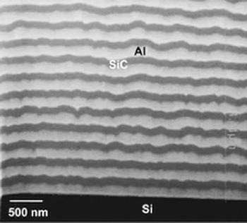
The model system considered in this study consists of alternating layers of aluminum and silicon carbide created by physical vapor deposition sputtering on a silicon substrate. The system contains 41 layers, and each layer is approximately 50 nm thick. The microstructure of the individual layers was characterized using a dual beam focused ion beam technique and scanning electron microscopy (SEM). A SEM-generated cross-sectional view of the material system is shown in Fig. 1.
Scanning electron micrograph of the cross-section of Al/SiC multilayer thin films on a Si substrate. Reference Chawla, Singh, Shen, Tang and Chawla30

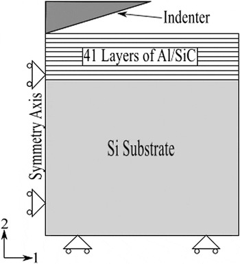
The finite element model used in the indentation analysis consists of 41 alternating Al and SiC thin films on a substrate of Si. This corresponds to the actual nanolayered system studied previously. Reference Tang, Shen, Singh and Chawla27 A schematic of the baseline model is shown in Fig. 2. Both the top layer (in contact with the indenter) and the bottom layer (adjacent to the Si substrate) are Al. A conical diamond indenter with a semiangle of 70.3° is assumed. This indenter geometry results in the same projected contact area for a given depth as that of a Berkovich indenter in common nanoindentation experiments. Use of the conical indenter is a practical way to model the indentation process in a two-dimensional setting. Reference Fischer-Cripps31 The model is axisymmetric with the left boundary being the symmetry axis. The entire specimen is 40 µm in lateral span (radius) and 43 µm in height. The thicknesses of the individual Al and SiC layers are 50 nm each. During deformation, the left and bottom boundaries are allowed to displace only in the axial and radial directions, respectively. The right boundary is not constrained. The top Al surface, when not in contact with the indenter, is also free to move. When contact with the indenter is established, the surface portion engaged by the indenter directly interacts with the indenter. The coefficient of friction between the indenter and the top surface is 0.1, which is a typical value for the diamond/metal contact surface. Reference Lide32,Reference Bucaille, Stauss, Schwaller and Michler33
Schematic showing the Al/SiC laminates above a Si substrate and the boundary conditions used in the axisymmetric model. The left boundary is the symmetry axis. The entire specimen is 40 μm in lateral span (radius) and 43 μm in height. Each individual Al and SiC layer is 50 nm thick.

Approximately 125,000 fully integrated linear axisymmetric elements are used in the finite element model with a finer mesh size near the upper-left corner of the test material. The element size near the indenter is 5 nm and increases in size far from the indenter. The indenter consists of approximately 8000 elements with an element size of 10 nm near the tip. The mesh was created using CUBIT (Sandia National Laboratories; Albuquerque, NM). The finite element program ABAQUS (Version 6.13, Dassault Systemes Simulia Corp.; Providence, RI) was used to carry out the analysis.
The Young's moduli for Al and SiC are assumed to be 59 and 277 GPa, respectively. Nanoindentation of single-layer Al and SiC films provided the moduli for these materials. The somewhat lower modulus of SiC, relative to crystalline SiC (which is around 410 GPa), is due to the fact that the physical vapor deposited SiC layers in the present case were amorphous. Reference Deng, Chawla, Chawla, Koopman and Chu34 The Poisson's ratios for Al and SiC were taken as 0.33 and 0.17, respectively. The plastic response of Al was based on the tensile loading data of single-layer Al with initial yield strength of 200 MPa. Rate-independent isotropic elastic–plastic response was assumed with plastic yielding following the von Mises criterion with isotropic hardening and the incremental flow theory. The piecewise linear strain hardening response features hardening slopes of 199.33 MPa from initial yielding up to the strain of 50.51% and then 39.97 MPa up to the strain of 300.68%, beyond which perfect plasticity ensues. SiC is a much more brittle material. Nevertheless, a very high “yield point” of 8770 MPa (estimated from the indentation hardness of a single-layer SiC film Reference Phillips, Clemens and Nix16 ) was used followed by perfect plasticity. This assumption is necessitated by the fact that a purely elastic SiC in the model will generate unrealistically high loads during the indentation simulation, and it is validated by the fact that in the experiment the SiC layers exhibited a glassy/plastic-type response due to the amorphous nature of the film. Reference Sun, Chu, Lin, Shen and Chawla35 Both the Si substrate and the indenter are assumed to remain elastic. The Young's modulus and Poisson's ratio of the Si substrate are 187 and 0.28 GPa, respectively. The Young's modulus and Poisson's ratio of the diamond indenter are 1141 and 0.07 GPa, respectively. All the interfaces between different materials in the composite structure are modeled as perfectly bonded. Although internal damage can occur during indentation loading, Reference Chawla, Singh, Shen, Tang and Chawla30 the present analysis assumes an intact multilayer structure for the purpose of gaining a baseline understanding of the deformation features.
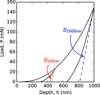
The indentation-derived elastic modulus and hardness were directly obtained from the finite element modeling. Figure 3 shows the modeled load–displacement curve at indentation depths of both 500 and 1000 nm. The contact stiffness at the onset of unloading, S, is defined as Reference Oliver and Pharr19 :
 $$S = \beta {2 \over {\sqrt \pi }}{E_{{\rm{eff}}}}\sqrt A \quad ,$$
with
 $${1 \over {{E_{{\rm{eff}}}}}} = {{1 - {\nu ^2}} \over E} + {{1 - \nu _{\rm{i}}^2} \over {{E_{\rm{i}}}}}\quad ,$$
where A is the projected contact area at onset of unloading; β is the indenter geometry-dependent dimensionless parameter; E and ν are the Young's modulus and Poisson's ratio, respectively, of the material being indented; and E i and νi are the Young's modulus and Poisson's ratio, respectively, of the diamond indenter. In the simulation, the parameter β first was calibrated with a pure Al body of the same geometry as the entire multilayers/substrate assembly (Fig. 2), and a value of 1.06 was determined. This was accomplished by making certain indentation-derived Young's modulus, which is equivalent to the input value used in the finite element analysis. When calculating the projected contact area A, the last nodal point on the top surface in contact with the indenter was identified in the deformed mesh. Thus, the effect of pileup was automatically taken into consideration. The determination of the composite modulus E requires a known Poisson's ratio ν. Here, a separate finite element analysis of uniaxial loading of the Al/SiC laminates was used to determine ν, Reference Tang, Shen, Singh and Chawla36,Reference Shen37 which results in a value of 0.25. Finally, the hardness of the material H was calculated from
 $$H = {{{P_{{\rm{Peak}}}}} \over A}\quad ,$$
with P Peak being the load at a given indentation depth and A being the corresponding projected contact area.
Load–displacement curves for indentation depths of 500 and 1000 nm. The contact stiffness S at the onset of unloading is also shown for both indentation depths.

The contact stiffness at the onset of unloading, S, for a Berkovich indenter is traditionally calculated experimentally using the relationship formulated by Oliver and Pharr. Reference Oliver and Pharr19 The unloading load–displacement data are described by
 $$P = C{\left( {h - {h_{\rm{f}}}} \right)^m}\quad ,$$
where P is the load, (h − h f) is the elastic displacement, and C and m are the material constants. The contact stiffness is then found by analytically differentiating Eq. (4) and evaluating the derivative at the peak load and displacement. To calculate the contact stiffness at the onset of unloading from the present finite element model, a least-squares linear regression is fitted to a portion of the unloading load–displacement data. In the current study, the initial 2% of the unloading curve is used to fit the linear regression unless stated otherwise. An example of the fit is shown in Fig. 3 for indentation depths of 500 and 1000 nm and is denoted by S. Using the linear regression is useful for estimating the effect unloading-induced plasticity has on the indentation-derived modulus.
For the metal-ceramic multilayer systems in question, not only will plasticity develop during the indentation but plasticity can also continue to develop during the unloading as mentioned in the introduction. To determine if unloading-induced plasticity affects the indentation-derived modulus, modifications are made to the material models discussed above. During the loading step, the materials are as described above, but during unloading, the materials are artificially enforced to remain elastic for this additional consideration. This is accomplished by setting the yield strength of all materials during unloading to be very large. Thus, results can be compared with the regular models where plastic deformation in the metallic layers does occur during unloading.
A. Model validation
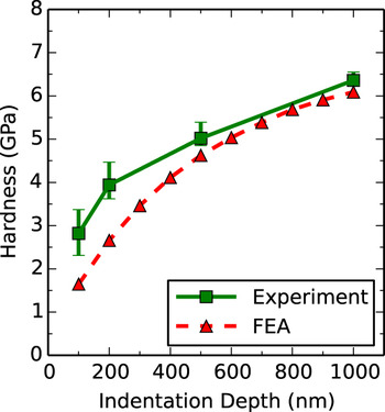
To provide a sound basis for comparing the indentation-derived modulus calculated with and without unloading-induced plasticity, model validation is performed. The model system previously has been characterized experimentally using nanoindentation. Reference Tang, Shen, Singh and Chawla27,Reference Chawla, Singh, Shen, Tang and Chawla30 Indentation-derived composite hardness and modulus have been calculated over a range of 0–2000 nm, and comparisons from experiments and models are made from 0 to 1000 nm. Figure 4 shows the comparison between the indentation-derived hardness. The finite element model matches the experimental trend reasonably well—particularly the shape of the curve below the indentation depth of 500 nm. For indentation depths beyond 500 nm, the model matches the experiment very well with data that fall within the error of the experiment.
Comparison of the experimental Reference Tang, Shen, Singh and Chawla27 and model indentation-derived hardness.

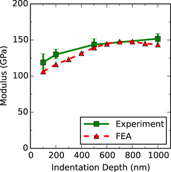
Figure 5 shows the comparison between the experiment and model for the indentation-derived elastic modulus. The experimental and model data show good agreement. At indentation depths of 100 and 200 nm, the model has moduli values that are marginally lower than the experimental moduli. For indentation depths greater than 200 nm, the model and the experiment match very well. The finite element results fall within the error of the experimental results. The agreement between the two sets of data provides a sound basis for further comparisons to be made.
Comparison of the experimental Reference Tang, Shen, Singh and Chawla27 and model indentation-derived moduli.

III. RESULTS AND DISCUSSION
A. Evolution of plastic strain field
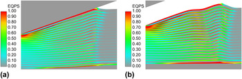
The development of plastic strain during the indentation process is a known phenomenon. Plasticity commonly occurs in homogeneous materials directly beneath the indenter as well as at the film–substrate interface for thin metallic films. For the multilayer system considered, a more complex deformation pattern exists. Figure 6 shows the equivalent plastic strain (EQPS) in the model system for an indentation depth of 1000 nm. At the maximum indentation depth, the plastic strain directly beneath the indenter is highest. There are also large amounts of plastic strain at the Al/SiC interface in each Al layer and at the interface between the bottom Al layer and Si substrate. In the unloaded state, the plastic strain distribution changes. The volume of material with large plastic strain (EQPS > 1) increases. Also, there is a large increase in the plastic strain at the Al/Si interface. This shows that the unloading process does indeed result in an increase in plastic strain. To better understand the change in plastic strain from loaded to unloaded state, the net change of EQPS, ΔEQPS, will be considered subsequently.
Equivalent plastic strain contours for an indentation depth of 1000 nm in the (a) loaded and (b) unloaded states.

Though plastic strain is common during the indentation, it is the presence of unloading-induced plasticity that will affect the indentation-derived modulus. During indentation, the metallic layers flow away from the center of indentation. This, in conjunction with the metallic layers on both sides of the ceramic, allows the ceramic to bend significantly. Reference Singh, Chawla and Shen38 This interaction between Al and SiC layers results in a very complex unloading scenario. Unlike homogeneous systems in which material is able to relax during unloading, the metallic layers in the multilayer system are constrained by the ceramic layers during unloading. This extra constraint imposed by the hard ceramic layers not only alters the elastic unloading behavior of the metallic layers but also results in significant plastic strains at the metal/ceramic and bottom-metal/substrate interfaces—particularly for relatively deep indentation depths.
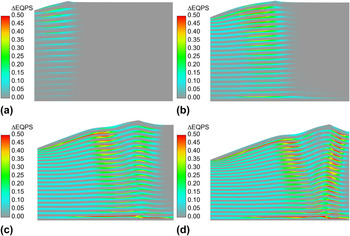
The increase in EQPS due to unloading, ΔEQPS, is shown in Fig. 7 for indentation depths ranging from 200 to 1000 nm. For indentation depths of 200 and 500 nm, the peak increase in EQPS is 0.5 and 0.9, respectively. The location of the peak in both cases is in the second metallic layer at its interface with the ceramic. The distribution of the increase in plastic strain is focused mostly beneath the indentation location except for the bottommost metallic layer. For indentation depths of 800 and 1000 nm, the increase in plastic strain is much more distinct. At 800 and 1000 nm, the plastic strain in the metallic layer increases by 1.4 and 2.2, respectively, and is located in the bottommost metallic layer. The plastic strain near the top of the system and directly beneath the indentation is consistent for indentations at and above 500 nm. Note that buckling of the top layers occurs during unloading for deep indentations, and strong unloading-induced plasticity in the upper layers appears to be associated with the buckling deformation. In the bottommost metallic layer, the largest increase in plastic strain occurs at the Al/SiC interface—not the Al/Si interface. The deeper indentation results in an increase in plastic strain away from the indentation site with an increase radially outward from the indentation. Particularly at 1000 nm, the increase in plastic strain is most complex with the maximum ΔEQPS values greater than 0.5 in each metallic layer. At this penetration depth, the bottommost metallic layer has formed a clear shear band between the SiC and Si. Although there is a significant increase in plastic strain during the entire unloading phase, the amount that occurs during the onset of unloading needs to be investigated.
Contour images of the difference in equivalent plastic strain (ΔEQPS) between the unloaded and loaded state in the metallic layers near the indentation site after unloading for indentation depths of (a) 200 nm, (b) 500 nm, (c) 800 nm, and (d) 1000 nm.

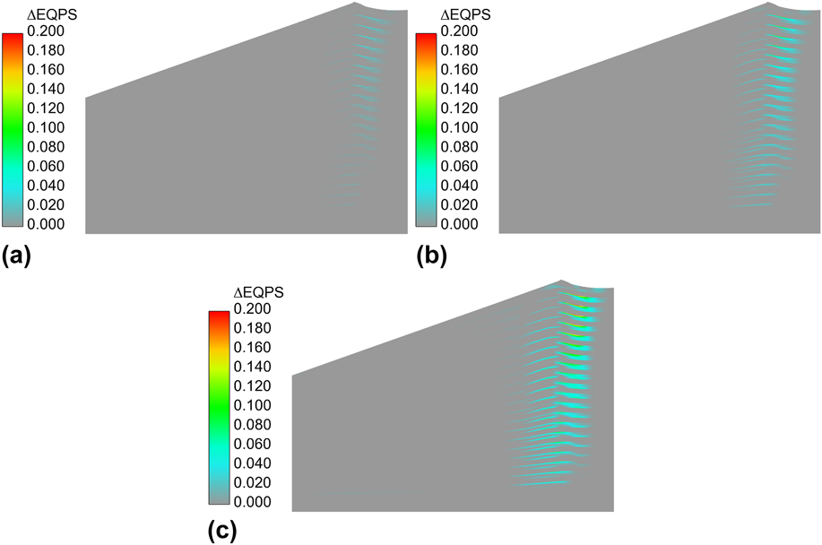
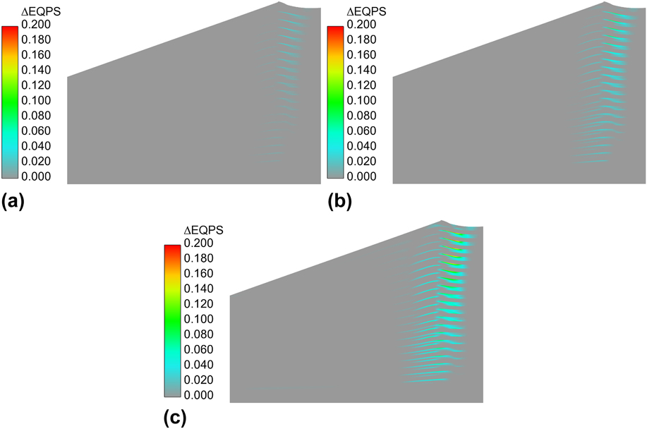
The increase in plastic strain during unloading at various stages of unloading is shown in Fig. 8 for an indentation depth of 1000 nm. As discussed previously, the contact stiffness at the onset of unloading is calculated from the finite element model by linear regression of 2% of the unloading curve. Image (a) shows the increase in plastic strain after the indenter is unloaded 2% from the peak load. At the 2% unloaded state, the maximum increase in plastic strain is approximately 0.05 and is focused radially outward from beneath the indenter. At (b) 5% and (c) 10% unloaded states, the maximum increase in plastic strain is 0.12 and 0.23, respectively. For each case, the increase in plastic strain does not occur directly below the indenter. The largest increase occurs in the second and third metal layers. The increase of plastic strain at the onset of unloading confirms that the assumption of initial elastic unloading is not valid for the multilayer system in question. Therefore, the sensitivity of the indentation-derived elastic modulus to the presence of unloading-induced plasticity warrants further investigation.
Contour images of the difference in equivalent plastic strain (ΔEQPS) between the loaded and (a) 2%, (b) 5%, and (c) 10% unloaded states for an indentation depth of 1000 nm.
B. Indentation-derived elastic modulus
The previous section established that the plastic strain in the metallic layers of the model system increases at the onset of unloading. In this section, the effect of unloading-induced plasticity on the indentation-derived elastic modulus is presented. To explicate this effect, the indentation-derived modulus is calculated using standard unloading data and artificially enforced elastic unloading data; the resulting data sets are compared. Standard unloading data refer to data obtained from a model that is allowed to develop plasticity during unloading. The artificially enforced elastic unloading data refer to data obtained from a model that is not allowed to develop plasticity during unloading. To establish a basis for the comparison, three cases are presented. First, the indentation-derived elastic modulus of a homogeneous Al film on a Si substrate is considered. Second, the multilayer model system is analyzed. Third, alternating layers of Al and SiC on a different substrate material (bearing the effective property of Al/SiC multilayers, as explained below) are examined.
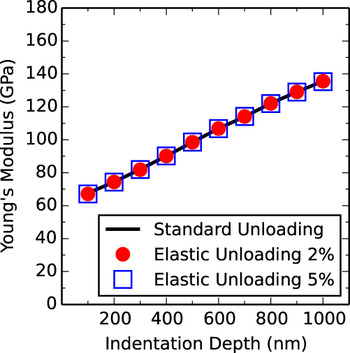
A homogeneous film on a thick substrate is not expected to exhibit any unloading-induced plasticity; therefore, an Al film on a Si substrate is useful for making an initial comparison between standard unloading and forced elastic unloading. Figure 9 shows the indentation-derived elastic modulus of an Al film on Si substrate. In the figure, the modulus from standard unloading data using the initial 2% of the unloading curve is compared to the modulus from enforced elastic unloading data using both 2 and 5% of the initial unloading curve. The indentation-derived modulus of the Al film exhibits substantial substrate effects as the modulus monotonically increases as the indentation depth increases. The standard unloading and the forced elastic unloading match exactly. Independent of how much unloading data are used in the modulus calculation, the forced elastic unloading matches the standard unloading. This confirms that there is no unloading-induced plasticity in the Al film.
Indentation-derived Young's modulus of homogeneous Al film on Si substrate for standard unloading and forced elastic unloading calculated using the top 2 and 5% portions of the unloading curve.

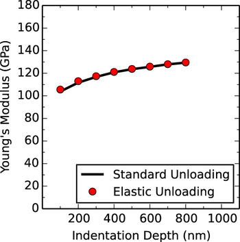
The second of three cases considered is the multilayer model system consisting of alternating layers of Al/SiC on a Si substrate. (The indentation-derived modulus for this system is shown in Fig. 5 to match well with experimental results.) The data in Fig. 10 show the comparison of standard and forced elastic unloading both for 2 and 5% unloading. For indentation depths less than 500 nm, the difference between the standard and elastic unloading is negligible. There is a small difference between the 2 and 5% unloading above 500 nm. The difference in the standard unloading curves is likely due to the difference in the amount of plasticity that has developed during unloading. Regardless of the amount of unloading considered in the contact stiffness calculation, the modulus-depth response is consistent in shape and only differs in magnitude.
Indentation-derived Young's modulus of Al/SiC multilayer system on Si substrate for standard and forced unloading—both calculated using 2 and 5% unloading.

Unlike the standard unloading moduli, the moduli for the forced elastic unloading do not appear dependent on the portion of the unloading curve used in the calculation. At indentation depths greater than 500 nm, the standard and forced elastic unloading moduli differ substantially. At these depths, the standard unloading response begins to plateau while the forced elastic unloading continues to increase. For an indentation depth of 1000 nm, the two moduli differ by nearly 30 GPa. It is established in Fig. 8 that the amount of unloading-induced plastic strain at 1000 nm during the initial stages of unloading is relatively small. Nonetheless, this small amount of unloading-induced plastic strain has a significant impact on the derived modulus. Lastly, the four sets of data presented in Fig. 10 suggest that the difference between standard and forced elastic unloading is not sensitive to the percentage of the unloading curve used in calculating the contact stiffness. Therefore, the presence of unloading-induced plasticity can have a substantial effect on the indentation-derived modulus for this multilayer system.
The relatively high stiffness of the substrate material in thin film applications can impact the indentation-derived hardness and elastic modulus of the structure. The third case considered evaluates the effect of the substrate on the indentation-derived modulus. In this model, the Si substrate is replaced with a material representing the homogenized Al/SiC composite. The elastic modulus and stress–strain response of the effective substrate were determined from uniaxial compression modeling of an Al/SiC multilayer composite. Reference Jamison and Shen39 The modulus of the effective substrate is nearly half that of Si. Figure 11 shows the indentation-derived elastic modulus of the multilayer Al/SiC structure on an effective substrate for both standard and elastic unloading. Given a substrate that is approximately the same modulus of the multilayer system, the overall modulus still increases with indentation depth but to a much smaller extent compared to Fig. 10. With an effective substrate the standard and forced elastic unloading results are essentially identical. This implies that the unloading-induced plasticity exhibits some degree of dependency on a substrate material substantially stiffer than the multilayer thin film structure.
Indentation-derived Young's modulus of an Al/SiC multilayer system on an Al/SiC effective substrate Reference Jamison and Shen39 for standard and forced unloading.

Based upon these results, the unloading-induced plasticity can have a direct influence on the indentation-derived elastic modulus. At the deepest indentation depth considered, the presence of plasticity results in an underestimation of actual composite modulus of the multilayers.
C. Cyclic indentation behavior and modulus determination
A common practice when performing nanoindentation experiments is to load and unload the indenter multiple times to minimize the possible effect of plastic unloading. Reference Oliver and Pharr19 This practice has been shown to work well for homogeneous materials or monolayer thin films. When conducting nanoindentation on a “normal” material, such as a homogeneous elastic–plastic solid, one encounters both elastic and plastic deformation during loading. The elastic strains are recovered in the unloading phase. If the specimen then is cyclically reloaded and unloaded, the load–displacement curve will follow the prior unloading path, which characterizes the elastic nature of the process. Reference Oliver and Pharr40 While this is true for most homogeneous elastic–plastic solids and monolayer thin films, it does not always hold true for multilayer thin films. Previous studies have shown that for a multilayer structure the unloading and reloading response is different and results in a hysteretic response. Reference Shen, Blada, Williams and Chawla29 The hysteresis of the load–displacement curve suggests the continual increase in plasticity during both the unloading and reloading phases.
The present study seeks to further investigate the effect of cyclic indentation on the indentation-derived modulus and how this relates to unloading-induced plasticity. To do so, the cyclic indentation response of the multilayer system discussed above will be modeled. The hysteresis of the load–displacement response will be analyzed to determine if it decreases at high cycle counts. The composite modulus derived from cyclic indentation will be compared to both those obtained from the standard and forced elastic unloading response of a single indentation. Lastly, the plastic strain induced by unloading during cyclic indentation will be considered.
Cyclic indentation was simulated by first loading the indenter to 80 mN, which corresponds to an indentation depth of approximately 775 nm. Unloading to 10% of the peak load, 8.0 mN, then follows. Subsequent cycles were carried out between these maximum and minimum loads, and a total of 15 cycles were performed. The simulation was initialized using displacement control boundary conditions. When the indentation load had reached more than 80% of the peak load, the boundary condition was updated to use load control. All subsequent cycles were then simulated using load control. The material properties are consistent with the previous model (Al/SiC multilayers on Si substrate) and forced elastic unloading is not considered.
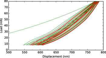
The simulated load–displacement curves of the Al/SiC multilayer system for a total of 15 cycles are shown in Fig. 12. In the figure, cycles 5, 10, and 15 are highlighted. For the purpose of clarity, the initial part of the first loading curve is not shown. It can be seen that the load–displacement loop persists from cycle to cycle, but it shifts left-to-right toward larger displacements. In other words, there is a tendency for the indenter to penetrate deeper as cycling continues under a constant load amplitude. This may be viewed as the indentation version of the “cyclic creep” phenomenon typically observed under uniaxial loading. Reference Suresh41 It should be noted that the present numerical model only includes rate-independent plasticity; hence, increasing penetration is not caused by any viscous effect but purely a consequence of cyclic plasticity under highly constrained conditions. A stabilized hysteresis loop has not been reached after the completion of 15 cycles; however, the rate of change of indentation displacement is decreasing. This suggests that the amount of loading and unloading-induced plasticity in the metallic layers is slowly decreasing toward a constant value.
Simulated 15 full cycles of indentation load–displacement response for the Al/SiC multilayer system on Si substrate. Cycles 5, 10, and 15 are highlighted.

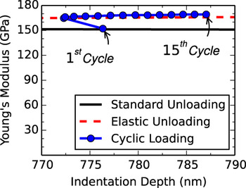
The indentation-derived elastic modulus was shown in the previous section to be sensitive to the presence of unloading-induced plasticity. From Fig. 12, it is apparent that the plastic state is changing in each cycle. Therefore, it is possible that a relationship exists between the moduli derived from the forced elastic unloading and cyclic indentation. Figure 13 shows the indentation-derived elastic modulus for the Al/SiC multilayer system for cyclic as well as single cycle indentation over the indentation range considered. Between 750 and 800 nm, the indentation-derived standard and forced elastic unloading moduli differ by more than 15 GPa. The modulus as derived from cyclic loading increases significantly from cycle 1 to cycle 2. It is noted that from cycle 2 onward, the indentation depth at each peak load increases with cycles. However, there is a decrease in penetration depth from cycle 1 to cycle 2. This may be attributed to the somewhat “irregular” load–displacement response seen during the loading phase of the second cycle (Fig. 12), which possibly is associated with the buckling of layers observed in Fig. 7(c).
Indentation-derived Young's modulus of an Al/SiC multilayer system on Si substrate for cyclic indentation of peak load 80 mN compared to standard and forced elastic unloading of single cycle indentation.

The increase in the indentation-derived modulus between the first and second cycle is 8% and is the single largest change through the 15 cycles. After the first cycle, the indentation-derived modulus changes by less than 1% each cycle. After 15 cycles, the cycle-to-cycle variation in derived modulus is nearly zero. Although the plastic strain in the structure continues to increase cycle-to-cycle (Fig. 12), the amount of plasticity that develops during the initial unloading is likely very low. Therefore, for this material system, the indentation-derived elastic modulus will not be affected by unloading-induced plasticity after the second cycle.
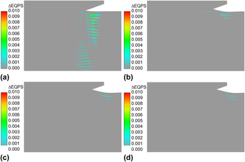
The cyclic indentation-derived modulus in Fig. 13 suggests that the unloading-induced plasticity, at the beginning of the unloading, decreases substantially from cycle to cycle. Figure 14 shows the contour plots of the increase in EQPS at the early stages of unloading in different cycles. The figure confirms that with subsequent cycles there is very little plasticity at the beginning of unloading (where the elastic modulus is evaluated). During the first unloading cycle, the maximum amount of unloading-induced plasticity at 2% unloading is 0.015. Upon further cycling, the peak unloading-induced plasticity at 2% unloading decreases to approximately 0.0025 and remains constant through cycle 15. The unloading-induced plasticity between 100 and 98% of the peak load does not occur directly beneath the indenter after the first cycle and is located radially outward from the pile-up. Since the increase in plastic strain is not located directly beneath the indenter, it does not directly affect the modulus evaluation. This is observed in Fig. 13, as the elastic modulus is nearly constant after the first few cycles.
Unloading-induced equivalent plastic strain (ΔEQPS) at 98% of the maximum load of 80 mN during cyclic indentation for cycles 1, 5, 10, and 15.

The correlation between the modulus from the forced elastic unloading and cyclic loading indicates that a method exists to determine the modulus experimentally. For a given indentation depth, using a single cycle indentation result will likely underpredict the indentation-derived elastic modulus. Therefore, it is suggested that in actual nanoindentation testing of metal/ceramic multilayer systems, multiple indentation cycles should be performed to avoid the effect of any unloading-inducted plasticity.
D. Varying thicknesses of a multilayer system
The thickness of individual layers in metal and ceramic multilayer systems can vary depending on application and design. In the material system discussed above, the individual layers are assumed to be of equal thickness. To further explore the effect of unloading-induced plasticity, two variations of the Al/SiC multilayer system are considered. In both variations, the total thickness of the system is maintained to be the same as the original system, 2.05 μm, which consists of 41 alternating layers that are 50 nm thick. Both variations have 41 layers. In the first variation (a), each Al layer is 20 nm and each SiC layer is 80 nm for an Al to SiC thickness ratio of 0.25. In the second variation (b) each Al layer is 80 nm and each SiC layer is 20 nm for an Al to SiC layer thickness ratio of 4.0. Cyclic indentation is performed on each variation of the multilayer Al/SiC system to a similar indentation depth as shown in Fig. 13.
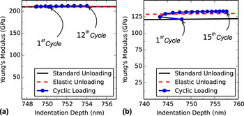
The cyclic indentation-derived elastic modulus of the variations on the Al/SiC multilayer system is shown in Fig. 15. Layer thickness ratios of 0.25 and 4.0 are shown in images (a) and (b), respectively. Note that, for easy visualization of fine features, the horizontal and vertical scales in these presentations are made different from those in Fig. 13. For a low thickness ratio, image (a), there is no appreciable difference between the standard and elastic unloading results. This suggests that, although the Al layers are constrained by thick SiC layer, the high stiffness and high thickness fraction of the SiC layers overcome any possible unloading-induced plasticity. The change in the modulus, cycle-to-cycle, is very small, which implies there is essentially no effect of unloading-induced plasticity in the thin Al layers. For a large thickness ratio, image (b), the unloading-induced plasticity does influence the derived modulus. Similar to the results shown in Fig. 13, the indentation-derived modulus increases cycle-to-cycle. While the SiC layers are thinner than the original system, the SiC layers still impose a constraint on the Al layers causing unloading-induced plasticity. The Young's modulus from the first indentation is 121 GPa, and the final indentation is 133 GPa—an increase of 10%. Lastly, in both models the indentation depth decreases from the first to second cycles for reasons discussed previously.
Indentation-derived Young's modulus of Al/SiC multilayer system from cyclic loading for varying thickness: (a) Al to SiC thickness ratio of 0.25 and (b) Al to SiC thickness ratio of 4.0.

Figures 13 and 15 show that unloading-induced plasticity can affect the composite modulus of the multilayer system. Figure 15(a) shows that thin Al layers allow for very little unloading-induced plasticity, while Fig. 15(b) shows the opposite. The effect of unloading-induced plasticity on elastic modulus as shown in Fig. 15(b) is not significantly different than that shown in Fig. 13. For layers of equal thickness, the modulus increases by 8%. For large thickness ratios (Al/SiC ratio of 4), there is a slightly larger increase in the modulus of 10%. Therefore, it is confirmed that using the contact stiffness after multiple indentation cycles to determine the multilayer modulus is a valid and useful approach.
E. Further discussion
In the present work, the analysis of plastic deformation is entirely modeling based. Computational modeling enables thorough control of material parameters and loading conditions, so their consequences can be investigated without ambiguity. Currently there is no experimental technique capable of directly quantifying the evolution of plasticity during the unloading phase of indentation. However, recent advances in the synchrotron-based x-ray diffraction approach have made possible the measurement of small-scale plastic deformation. Reference Feng, Budiman, Nix, Tamura and Patel42 This technique is potentially useful in probing the indentation-induced plastic strains, although not exclusively for the unloading-triggered plasticity. Nevertheless, a possible strategy is to apply the technique to postindented specimens with various cyclic indentation histories. The accumulation of plastic strains as a function of number of cycles may thus be compared with the numerical modeling result.
Finally, the focus of this study has been on a metal-ceramic multilayer system, specifically Al/SiC. Aluminum/SiC is used because of the differences in how these materials behave. Aluminum is much softer than SiC and has relatively low yield strength. On the other hand, SiC is much stiffer than Al and does not easily undergo plastic deformation. It is the interaction of these two behaviors that exacerbates the unloading-induced plasticity. It is theorized that different metal-ceramic multilayers will exhibit similar behavior if the difference in stiffness and strength of the two materials is large. Furthermore, it is possible that metal–metal systems Reference Wang, Misra and Hoagland17,Reference Budiman, Han, Li, Wei, Dickerson, Tamura, Kunz and Misra18,Reference Budiman, Narayanan, Berla, Li, Dickerson, Wang, Tamura, Kunz, Nix and Misra43 may exhibit similar behavior if the differences in stiffness and yield strength are sufficiently large. It is believed that when the difference in stiffness and yield strength is low, the effect of unloading-induced plasticity is minimized or eliminated.
IV. CONCLUSIONS
The effect of unloading-induced plasticity on the indentation-derived elastic modulus of a metal/ceramic multilayer composite was modeled and analyzed. The model system of alternating layers of Al and SiC on a thick Si substrate was the basis for the study. It was shown that plasticity develops during the unloading phase; most importantly, plasticity increases during the initial unloading. To elucidate the difference between standard unloading (which allows for plasticity) and purely elastic unloading, the unloading phase was forced artificially to remain elastic in a separate set of simulations. It was found that the elastic modulus determined by initial unloading is sensitive to the presence of unloading-induced plasticity. For indentation depths greater than 500 nm, the standard and forced elastic unloading results differed by as much as 20%.
Cyclic indentation of the model multilayer system was also analyzed. Beyond the first cycle, the cyclic indentation-derived modulus closely matched that obtained from the forced elastic unloading. After several cycles, the cycle-to-cycle difference in indentation-derived elastic modulus is less than 1%. At 15 cycles, there is no discernable difference in the derived modulus cycle-to-cycle. Unloading-induced plasticity is also shown to be dependent on the ratio of Al to SiC layer thickness with little effect of unloading plasticity occurring for small ratios. Therefore, to avoid the effects of unloading-induced plasticity, it is suggested that a minimum of several indentation cycles be applied when experimentally characterizing multilayer thin films. Lastly, it is recommended that further analysis be performed to characterize other metal–ceramic and metal–metal multilayer material systems.
ACKNOWLEDGMENT
Sandia National Laboratories is a multiprogram laboratory managed and operated by Sandia Corporation, a wholly owned subsidiary of Lockheed Martin Corporation, for the U.S. Department of Energy's National Nuclear Security Administration under contract DE-AC04-94AL85000.