1. Introduction
In tokamak plasmas, the plasma currents are usually driven by the toroidal electric field induced by the transformer. The electrons are accelerated by the electric field and slowed down by collisions with other particles (Jaspers et al. Reference Jaspers, Cardozo, Finken, Schokker, Mank, Fuchs and Schüller1994). Electrons that exceed the critical velocity (for which the collisional drag balances the acceleration by the field) are freely accelerated and can reach very high energies (Gill Reference Gill1993). These electrons are called runaway electrons. The disruption of plasma or low-density discharge will create a considerable number of runaway electrons. The high electric fields induced during the current quench phase of disruption may give rise to a large number of runaway electrons with energies that are predicted to be as high as several hundreds of MeV (Martin-Solis, Sánchez & Esposito Reference Martin-Solis, Sánchez and Esposito2000). The generation of runaway electrons following disruptions could damage the first wall. The suppression of runaway electrons during disruption is essential for the safe operation of International Thermonuclear Experimental Reactor (ITER).
The lower hybrid current drive (LHCD) and electron cyclotron current drive (ECCD) can improve the plasma performance by localized current drive or heating. The presence of waves can greatly affect the runaway production rate because of the quasi-linear diffusion of electrons by waves. A large number of fast electrons are generated by LHW and ECW through parallel velocity diffusion associated with Landau damping, and perpendicular velocity diffusion associated with cyclotron damping. The runaway production rate is found to be enhanced by many orders of magnitude in the presence of plasma waves (Liu et al. Reference Liu, Muschietti, Appert, Vaclavik and Boyd1980). Runaway production was also observed to be enhanced in LHCD with IBW in several kinds of target plasmas in the HT-7 tokamak (Chen et al. Reference Chen, Wan, Ling, Gao, Ti, Du, Sajjad, Lin and Shi2008). Experiments (Ando et al. Reference Ando, Ogura, Tanaka, Iida, Ide, Nakamura, Maekawa, Terumichi and Tanaka1986; Kawashima et al. Reference Kawashima, Yamamoto, Hoshino, Uesugi, Mori and Suzuki1991; Maehara et al. Reference Maehara, Yoshimura, Minami, Hanada, Nakamura, Maekawa and Terumichi1998) have shown that EC waves could couple to the fast electron tail sustained by LH waves. Since runaways represent a serious threat to tokamak vessel structures when they impinge on the vessel wall or plasma facing components, the avoidance of runaway electrons is one of the outstanding problems of the tokamak fusion reactor, especially during disruptions (Esposito et al. Reference Esposito, Martın-Solıs, Poli, Mier, Sanchez and Panaccione2003). Understanding the generation of runaway electrons under different scenarios is therefore important.
In the present paper, the behaviour of runaway production under the simultaneous application of ECCD and LHCD, as well as the LHCD only, plasmas are investigated. It is found that a large number of runaway electrons are produced after the termination of LH power by conversion of fast electrons into runaway electrons due to the fast electron tail extending above the runaway critical energy. However, in contrast to LHCD only discharges, during the simultaneous application of LHCD and ECCD discharges, runaway electrons cannot be created when LH power is switched off alone. The runaway production is observed to be enhanced until EC power termination. After an introduction of the experimental set-up in § 2, the new experimental results pertaining to discharge in LHCD and ECCD are described, together with a discussion of the correlation of the observed runaway enhancement with the fast electron flux and the electric field change when the waves were switched off in § 3. Finally, the conclusions are presented in § 4.
2. Experimental set-up
The HL-2A device is a medium-size tokamak with closed diverter chambers. It has a major radius of
 $R=1.65~\text{m}$
and a minor radius of
 $a=0.4~\text{m}$
. Sixteen toroidal field coils can create and maintain a toroidal magnetic field (
 $B_{t}$
) up to 2.8 T. A LH power of up to 1 MW at 2.45 GHz is available presently. The power spectrum of the launched wave can be adjusted in the range
 $2.4<n_{\Vert }<2.75$
. The HL-2A has a ECRH facility, consisting of four gyrotrons with a working frequency of 68 GHz, which operates in the ordinary mode for delivering 2 MW power with 1 s pulse width (Zhang et al.
Reference Zhang, Yang, Liu, Song, Yuan, Li, Zhou, Zhou, Yang and Chen2009). The Gaussian beam is injected into plasma from the low-field side (LFS) in the fundamental O mode. The steerable mirrors in the launcher can be rotated to choose the angle of injection in the toroidal and poloidal directions between
 $0^{\circ }$
and
 $30^{\circ }$
. It can carry out forward current driver and poloidal rotation changes for heating experiments.
The detection of runaway electrons in the HL-2A tokamak is performed by means of the combination of hard X-ray radiation (HXR) detector arrays and fast electron bremsstrahlung emission (FEB) measurement systems, as shown in figure 1. The HXR detectors monitor the thick target bremsstrahlung when runaway electrons are lost from the plasma and impinge on the vessel walls or plasma-facing components. The two NaI (Tl) detectors are located in the equatorial plane and each detector aims at a fixed limiter to monitor the tangential emission of HXR in the direction of motion of the electrons. The FEB emissions resulting from collisions between the fast electrons and the bulk plasma can provide considerable information on the dynamics of fast electrons and their wave power deposition profile. A FEB diagnostic system based on cadmium telluride (CdTe) is dedicated to detailed studies of the fast electron dynamics in the energy range of 10–200 keV in the HL-2A. The FEB diagnostic has a perpendicular viewing into the plasma on the equatorial plane and its line-of-sight passes through the plasma core. The hard X-ray spectra with eight different energy channels are measured (Zhang et al. Reference Zhang, Liu, Song, Yuan, Chen, Ji, Ding, Yang, Zhou and Li2010). The conversion of fast electrons into runaways is monitored by the combination of the FEB and HXR systems.
Schematic view of runaway measurement systems in the HL-2A. It includes two channel NaI HXR detection arrays and FEB diagnostic.

In addition, the ECE diagnostic is used for measurement of second harmonic X-mode electron cyclotron emission at a frequency range of 98–126 GHz having temporal (2.5 ms) and spatial (4 cm) resolutions. Since the ECE signal contains downshifted emissions emitted by runaways with rather low energy, it provides considerable information about the evolution of the fast electron population and low energy runaway population in plasma discharges.
3. Experimental results
The experiments were carried out in deuterium with a toroidal magnetic field
 $B_{t}=2.4~\text{T}$
, plasma current
 $I_{p}=100{-}300~\text{kA}$
and central line-averaged electron density
 $n_{e}=(0.8{-}1)\times 10^{19}~\text{m}^{-3}$
. In the discharges reported in this paper, the ECW with 260 kW were injected into the plasma during the current flat-top of discharges. In the case of ECCD at 68 GHz, the resonance layer was located in the plasma centre. The toroidal angle of all the ECW was 20°. To study the impact of LHCD with ECCD operation on runaway electron generation, LHCD only discharge and the combined LHCD and ECCD discharge with constant plasma parameters were performed in these experiments.
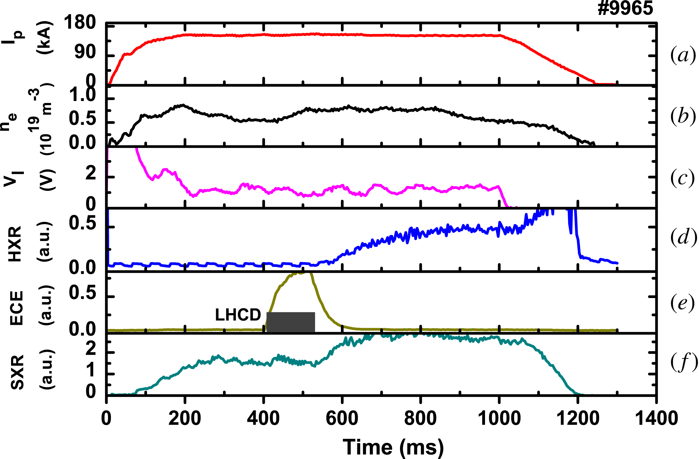
A typical LHCD reference discharge No. 9965 is illustrated in figure 2. The plasma current is approximately 140 kA, the central line-averaged electron density is approximately
 $0.8\times 10^{19}~\text{m}^{-3}$
and 190 kW LH power with
 $n_{\Vert }=2.75$
was launched into the plasma from 412 to 512 ms. This corresponds to a resonance energy of approximately 38 keV for the fast electrons created via Landau damping by LH waves. During the LHCD phase, a large number of non-thermal electrons are observed by the ECE signal, while the soft X-ray emission intensity (SXR) stays stationary, as illustrated by the curves (e) and (f). Because the ECE signal contains downshifted emissions from the fast electrons and runaways with rather low energy, the increase of ECE signal indicates an increase of the energetic electron population. The enhancement of runaway production subsequent to LH power termination is identified from the HXR flux. When the LH power was switched off, the ECE emission intensity decayed. The HXR emission signals increased progressively, which means that the enhancement of runaways was due to the termination of LH power.
Waveforms of LHCD discharge No. 9965. (a) the plasma current, (b) the central line-averaged electron density, (c) the loop voltage, (d) the hard X-ray radiation intensity HXR, (e) the central ECE emission intensity, (f) the soft X-ray emission intensity SXR. The shaded area in (e) indicates the time interval in which LHCD is applied.

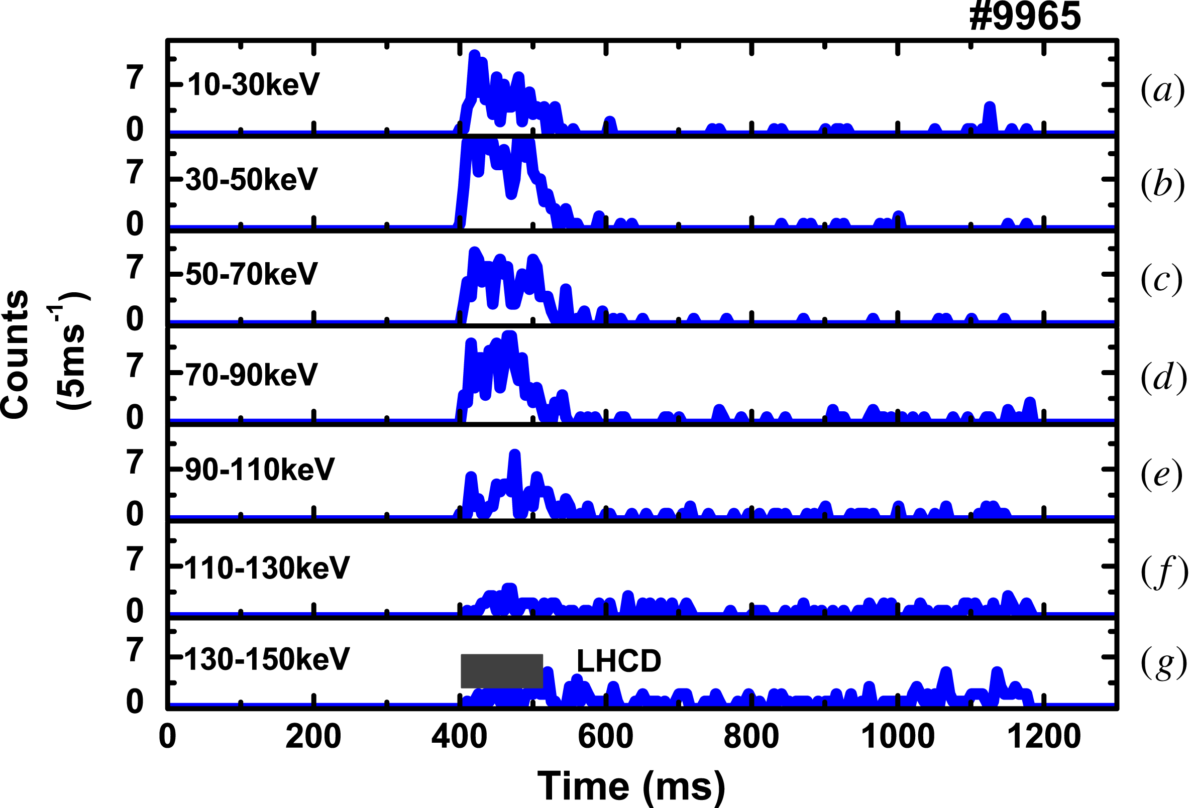
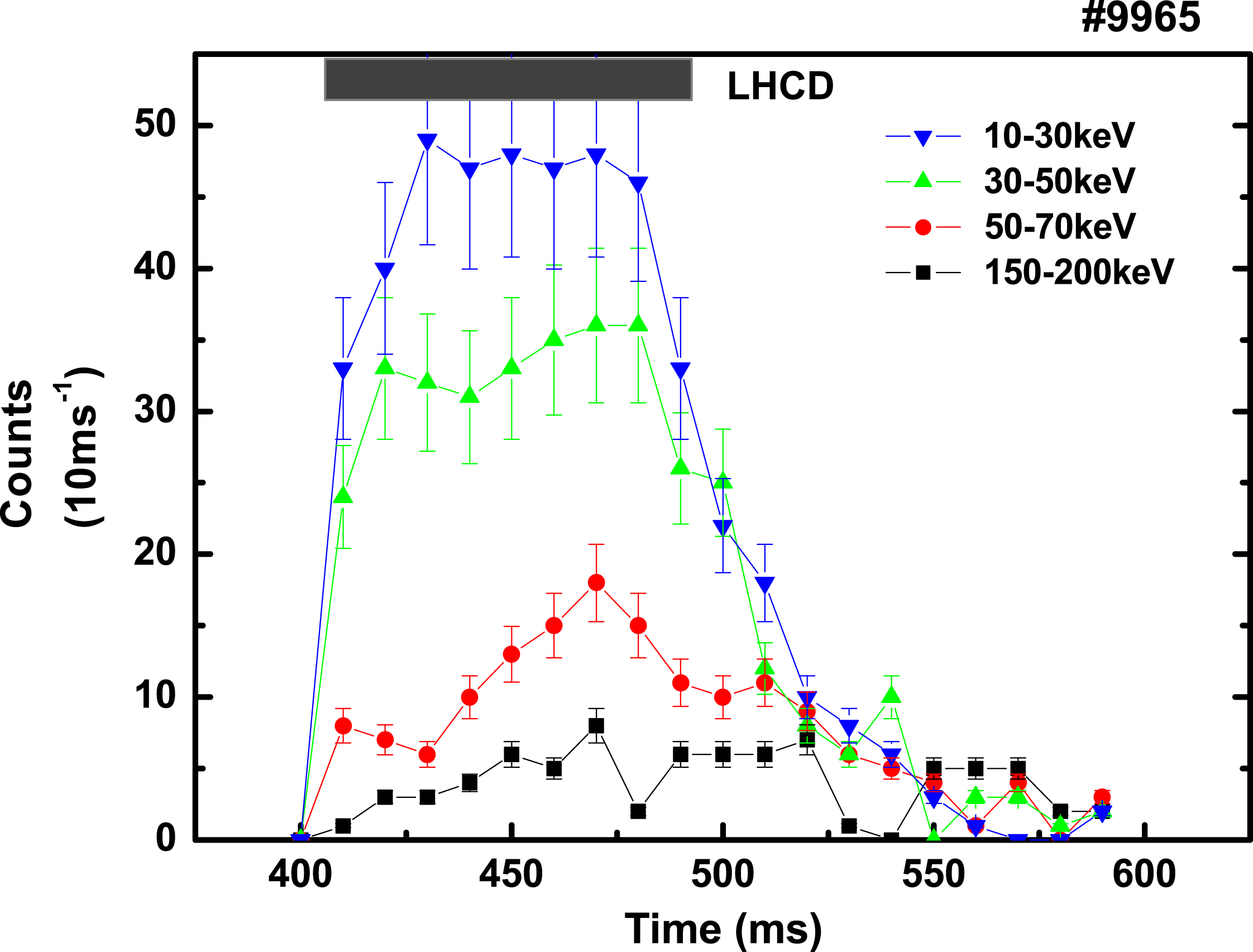
Additional information on the behaviour of the runaway population can be obtained from FEB measurement. The temporal evolutions of the HXR emission rates of the seven different energy channels are obtained from the FEB measurement system, as illustrated in figure 3. It can be seen that a large number of fast electrons are produced during the LHCD phase, and the energy distribution of the fast electrons clearly changes during the LHCD phase compared with the Ohmic heating phase. Before the LHW injection, the counts of HXR photons above 10 keV are negligible. During the LHCD phase, the energy of the fast electrons is mainly concentrated at low energy (10–110 keV). With the closing of the LH power, low energy (10–110 keV) fast electrons rapidly reduce, and high energy (110–150 keV) fast electrons gradually increase. According to the plasma parameters, the critical energy for the fast electrons to runaway is approximately 85 keV in the LHCD phase. The fast electron tail has extended above 150 keV as shown in figure 3. This case favours the generation of a runaway population. When the LH power is switched off, the FEB flux and ECE intensity decay. Direct losses due to diffusion of fast electrons can be neglected (Bartiromo et al. Reference Bartiromo, Barbato, Gabellieri, Spaziani, Tuccillo, Leuterer, Soldner, Gehre and Murmann1993). The time it takes for the fast electrons to slow down can be derived from the decay time of the FEB flux (Chen et al. Reference Chen, Fang, Dai, Duan, Zhu, Sun, Wan and Shi2011). Evolution of FEB flux in different energy ranges at the time of LH power termination are shown in figure 4. From figure 4, the time taken for the fast electrons to slow down is approximately 40 ms. Therefore, after termination of LH power within the time it takes for the fast electrons to slow down, the fast electron tail with energies higher than 85 keV contributes to runaways due to the residual loop voltage. The experimental results from the HXR and FEB emissions indicate that the enhancement of runaways after the termination of LH power is due to the fast electron seed population created in the LHCD phase, and the conversion of the fast electrons into runaways after LH power termination. This phenomena is similar to the enhancement of runaway production subsequent to LH power termination in the HT-7 tokamak (Chen et al. Reference Chen, Wan, Lin, Shi, Hu, Younis, Gong, Shan, Liu and Ding2006).
The temporal evolutions of the HXR emission rates of the seven different energy channels obtained from the FEB measurement system for discharge No. 9965. The shaded area indicates the time interval in which LHCD is applied.

Evolution of FEB flux in different energy ranges at the time of LH power termination for discharge No. 9965.

The energy of runaways is strongly sensitive to the value of the toroidal electric field. Any sudden change in this quantity should be followed by runaway population variety. A typical application of LHCD and ECCD discharge is shown in figure 5, where the time evolution of the main plasma parameters are plotted for discharge No. 9978. The plasma parameters were kept constant with respect to LHCD discharge No. 9965. In this pulse, 190 kW LHW power was launched from 412 to 590 ms and ECW power with 260 kW was launched into the plasma from 412 to 712 ms. Although two waves were injected into the plasma at the same time, their termination times are different. During simultaneous application of LHCD and ECCD phase (412–590 ms), the loop voltage decreases significantly from 1.5 to 0.7 V due to the non-inductive current drive. When the LH power was switched off, the loop voltage did not increase due to a slight decay of plasma density. During the common injection of LHW and ECW power, a large number of non-thermal electrons were observed by the ECE signal, as illustrated by the curves (e) and the soft X-ray emission intensity stayed stationary. From LHW termination to ECW termination, the ECE signal continues to increase due to a slight decrease of plasma density, while HXR is negligible. This indicates that the termination of LHW power did not lead to obvious runaway production. After the termination of ECW, the loop voltage increased to approximately 1.2 V and the ECE signal returned to its original level in the Ohmic phase. This is a clear indication that there was a large number of fast electrons in the LHCD with ECCD phase. After the EC power was switched off, the HXR emission intensity increased, as shown in figure 5(d). The experimental results from the HXR emission suggest that the production of runaways was undergoing linear growth after the termination of ECW power.
Waveforms of LHCD with ECCD discharge No. 9978. (a) the plasma current, (b) the central line-averaged electron density, (c) the loop voltage, (d) the hard X-ray radiation intensity HXR, (e) the central ECE emission intensity, (f) the soft X-ray emission intensity SXR. The shaded area in (e) indicates the time interval in which LHCD is applied. The shaded area in (f) indicates the time interval in which ECCD is applied.

The temporal evolutions of the HXR emission rates of the seven different energy channels obtained from the FEB measurement system are shown in figure 6. From figure 6, before the ECW and LHW power injection, there are few HXR photon counts above 30 keV. It can also be seen that a large number of fast electrons are produced during the ECCD and LHCD. The energy of the fast electrons is mainly concentrated at low energy levels (10–110 keV). At the termination of LH power, the number of fast electrons with energy of 10–110 keV remain constant, resulting from the ECCD. With the termination of ECW power, the number of low energy (10–110 keV) fast electrons is reduced rapidly, and the number of high energy (110–150 keV) fast electrons increases slowly. The conversion of low energy fast electrons into high energy fast electrons is monitored by the FEB diagnostic system subsequent to the ECW termination. When switching off the EC power, the loop voltage increases so as to maintain a constant plasma current. The increase in loop voltage results in a decrease of the runaway energy threshold. At the same time, switching off the EC power results in a more energetic fast electron population. The fast electron tail above the runaway energy threshold accelerate into runaway electrons due to the acceleration from the toroidal electric field.
The temporal evolutions of the HXR emission rates of the seven different energy channels obtained from the FEB measurement system for discharge No. 9978. The upper shaded area indicates the time interval in which LHCD is applied. The under shaded area indicates the time interval in which ECCD is applied.

According to Drecier theory, the critical energy
 $W_{c}=0.21n_{e,19}(\ln {\it\Lambda}/E~(\text{V}~\text{m}^{-1}))$
(keV) for runaway generation is calculated according to the central plasma density, the residual toroidal electric field inferred from the plasma loop voltage (
 $E\cong V_{l}/2{\rm\pi}R$
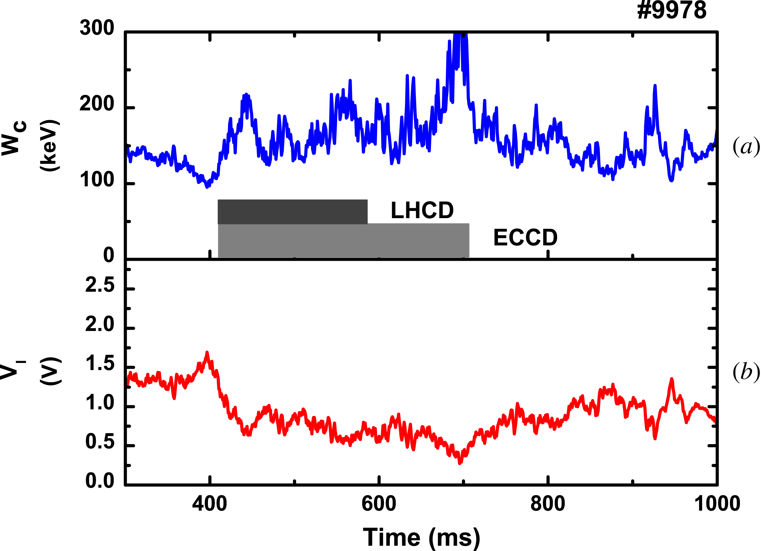
) and the Coulomb logarithm. Figure 7 shows the time traces of
 $W_{c}$
and loop voltage. It is found that the
 $W_{c}$
is approximately 120–200 keV during simultaneous application of LHCD and ECCD phase (412–590 ms). Due to the decline of residual electric field in this phase, a small population of wave resonant fast electrons in the tail margin extend to the runaway energy threshold according to figure 6, the most of fast electrons cannot be converted into runaway electrons. Therefore the HXR emission intensity is negligible. However, when the EC power is switched off, the increase in loop voltage results in a slight decrease of the runaway energy threshold. The fast electron tail close to the runaway energy threshold are accelerated into runaway electrons due to the acceleration from the toroidal electric field and a large number of fast electrons act as a seed population for runaway electrons. The presence of runaway seeds during waves and the increased toroidal electric field due to the termination of ECW favour the generation of runaway electrons. Thus, runaway production is enhanced when the ECW power is shut off.
Time trace of the loop voltage and the runaway critical energy for discharge No. 9978.

4. Conclusions
The effects of LHW and ECW terminations on the runaway production have been investigated in the HL-2A tokamak. A large number of fast electrons are generated by LHW and ECW through parallel velocity diffusion associated with Landau damping and perpendicular velocity diffusion associated with cyclotron damping. In the LHCD only discharge, a large number of runaway electrons are produced after the termination of LH power by conversion of fast electrons into runaway electrons due to the fast electron tail extending above the runaway critical energy. However, in contrast to LHCD only discharge, during the simultaneous application of LHCD and ECCD discharge, runaway electrons cannot be created when LH power is switched off alone. Runaway production after EC power termination is observed to be enhanced. The presence of runaway seeds and increased toroidal electric field favour the generation of runaway electrons. Since runaway enhancement has a deleterious effect on the safe operation of a device, this will be a significant issue for the next large-dimension machines.
Acknowledgements
The authors deeply acknowledge the assistance of the HL-2A group. One of the authors J.X.Z. would like to express his appreciation to Dr Z. Y. Chen for valuable suggestions. This work was supported by the National Natural Science Foundation of China (grant nos 11005036 and 11375004). The Scientific Research Key Foundation of the Education Department of Sichuan province (grant no. 15ZA0321).