NOMENCLATURE
Symbols
- °K
-
absolute temperature
- n
-
density
- T
-
temperature
Abbreviations
- C/C
-
carbon/carbon
- CBNU
-
Chonbuk National University
- DC
-
Direct Current
- EDS
-
Energy Dispersive X-ray Spectroscopy
- FE-SEM
-
Field Emission Scanning Electron Microscopy
- RF
-
Radio Frequency
1.0 INTRODUCTION
Thermal plasma can be generated by a direct current (DC) arc torch or an RF inductively coupled plasma torch. The temperature of the plasma is in the range of a few thousand °K to tens of thousands °K with a velocity ranging from several m/sec to supersonic values(Reference Boulos, Fauchais and Pfender1-Reference Anderson3). Thermal plasma has been used in a variety of applications from materials processing to aerospace materials testing. These applications can be divided into cases where thermal plasmas are used as heat transfer media and cases where the plasma-generated reactive species (i.e., dissociated or ionised radicals) are involved in the process chemistry.
Space vehicles re-entering the earth's atmosphere at high speed face a high enthalpy supersonic plasma flow that is induced by aerodynamic heating of the vehicle's surface(Reference Auweter-Kurtz, Hald, Koppenwallner and Speckmann4,Reference Marschall and Fletcher5) ; this can transfer a heat flux of more than several MW/m2 to the vehicle's surface, necessitating the development of the reliable thermal protection material. These materials must survive extreme environments with a combined (convective and radiative) heat flux of more than several MW/m2 and a peak pressure of a few atm. To develop the thermal protection material, plasma wind tunnels that can simulate the conditions during the supersonic flight and re-entry of space vehicles have been used(Reference Purpura, Filippis, Graps, Triponi and Savino6-Reference Matsui, Komurasaki and Arakawa9). High enthalpy and a high Mach number at the exit of the arc torch (with stable operation) are required, and (depending on the plasma-forming gases and the maximum heat flux) they can be utilised to test the thermal protection materials for a variety of missions.
Segmented arc plasma torches(Reference Marieu, Reynier, Marraffa, Filippisa and Caristia7,Reference Matsui, Komurasaki and Arakawa9) have also been adopted as a plasma source due to their advantages in terms of their ability to easily scale up the plasma input power to the MW level and also their ability to control the contamination induced by electrode erosion. They can produce high-enthalpy plasma flows that are sufficient to transfer steady-state heat fluxes greater than 10 MW/m2. In this type of plasma torch, increased plasma power can be accomplished by either increasing the arc voltage and the current by inserting segmented disks between the electrodes, or by extending the arc length. The high electrical power (up to the MW level) can be concentrated on a plasma-forming gas, leading to the production of high-enthalpy plasma flow for the thermal protection material testing under extreme conditions.
Carbon/carbon composites have been considered to be a promising thermal protection material due to their outstanding high-temperature strength, high thermal conductivity, and good thermal shock resistance(Reference Zaman, Li, Ikram, Li, Zhang and Guo10-Reference Cho and Yoon12). By utilising the plasma wind tunnel, we investigate the ablation characteristics of some carbon/carbon composites that are currently under development and analyse their relevance for use as the thermal protection materials.
2.0 DEVELOPMENT OF CBNU PLASMA WIND TUNNEL
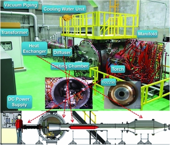
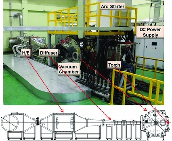
High-enthalpy plasma wind tunnels with power levels of 0.4 and 2.4 MW have been developed at CBNU in Korea to study performance of the thermal protection materials under high-temperature environments with emphasis on applications to aerospace vehicles and to develop new diagnostic techniques for understanding non-equilibrium plasma physics and chemistry in supersonic flow. The systems have similar designs. The plasma wind tunnel consists of a segmented arc plasma torch, a test chamber with a substrate manipulating system, a diffuser, a removable section, a heat exchanger and vacuum equipment as shown in Figs 1 and 2. At the diffuser, the supersonic flow from the plasma torch is funnelled directly in the exhaust to avoid unnecessary gas recirculation inside the test chamber, and the supersonic flow is broken and homogenised with a middle cone section, providing a uniform-temperature gas profile to the heat exchanger. The gas is sufficiently cooled at the heat exchanger for the vacuum pumps with the minimal pressure drop. The linear arrangement of the reactors, diffuser and heat exchanger offers an optimised design for the supersonic plasma wind tunnel. They are designed to produce a heat flux greater than 10 MW/m2, a level that is relevant for testing the thermal protection materials and to have high thermal efficiency, long life, and to produce a supersonic plasma flow with enthalpy greater than 10 MJ/kg for the 0.4 MW system and greater than 20 MJ/kg for the 2.4 MW system.
Layout of the 0.4 MW plasma wind tunnel.

Layout of the 2.4 MW plasma wind tunnel.

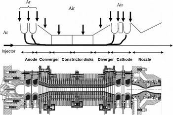
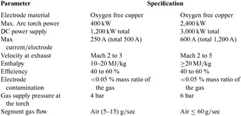
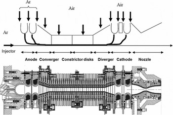
The segmented arc plasma torch that is employed in the plasma wind tunnels consists of a dual anode, a convergent part, constrictor disk parts, a divergent part and a dual cathode (Fig. 3). The electric arc is established between ring type electrodes that are made of oxygen-free copper. Metallic tubular disks are used to obtain a suitable arc column distance between the electrodes. These disks are electrically insulated from each other and from the electrodes. Each disk is independently cooled by de-ionised water. The number of installed constrictor packs can be changed in accordance with the required enthalpy level. An electric arc heats the gas to a high temperature. The gas is then injected tangentially between the segments at a high velocity to produce a swirl that stabilises the arc. An axial magnetic field is applied to the arc-foot by a permanent magnet inside each electrode to minimise electrode erosion caused by current concentration, and the arc-foot is rotated in the radial plane by a Lorenz force. The specifications of the torch and the plasma wind tunnel are listed in Table 1.
A schematic of the segmented arc plasma torch.
Specifications of the plasma wind tunnels

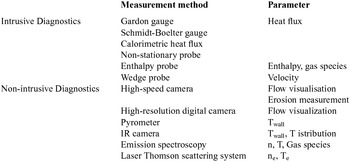
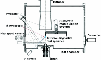
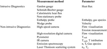
The test chamber was fabricated to allow for a wide range of material testing and plasma diagnostic experiments. The chamber (1.6 m diameter × 2.6 m long for the 0.4 MW system and 1.8 m diameter × 2.2 m long for the 2.4 MW system) is made of stainless steel with a water-cooled double wall. The substrate manipulation system allows for operation with three degrees of freedom under vacuum. Its four arms are cooled with water and are movable. Each arm is designed to install a heat flux probe, an enthalpy probe and test samples. Diagnostic systems include intrusive diagnostics such as an enthalpy probe with mass spectrometers, a heat flux probe and a wedge probe. They also include non-intrusive diagnostics such as a pyrometer, a fast camera, optical emission spectroscopy and a laser Thomson scattering system. The diagnostics of the plasma wind tunnel are listed in Table 2, and a schematic of their set-up in the test chamber is shown in Fig. 4.
Diagnostics of the plasma wind tunnel
A schematic of diagnostics set-up.

3.0 OPERATION CHARACTERISTICS OF THE CBNU PLASMA WIND TUNNELS
3.1 0.4 MW Plasma Wind Tunnel
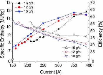
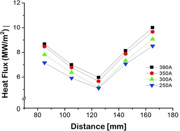
Figure 5 shows a variation of the specific enthalpy at the torch exit and the thermal efficiency as the input current increases with the gas flow rates ranging from 10 to 16 g/sec and the constant chamber pressure of 40 mbar. Plasma power increases as the input current and the gas flow rate increase. Smaller gas flow rates produce larger specific enthalpies but lower efficiency. Specific enthalpy at the torch exit increases as the input current increases, and smaller gas flow rates produce larger specific enthalpies. This indicates that in order to increase the specific enthalpy, both the power and the gas flow rate must be controlled. The thermal efficiency decreases as the input current increases, but remains large for large gas flow rates. Figure 6 shows the heat flux measured by varying the distance between the nozzle exit and the heat flux probe at a gas flow rate of 12 g/sec. Heat flux ranges from 5 to 10 MW/m2. Torch nozzle is optimised for specific gas flow, Mach number and pressure. Shock wave occurs at the operation outside this range and when the static pressure at torch exit differs from the chamber pressure. There is an oscillatory pressure pattern caused by expansion and compression of the shock waves that readjust the flow for the static pressure to reach the chamber pressure and that lead to the variation in the heat flux.
Dependence of the specific enthalpy and efficiency on the input current.

Dependence of the heat flux on the distance between the nozzle tip and the heat flux probe.

3.2 2.4 MW Plasma Wind Tunnel
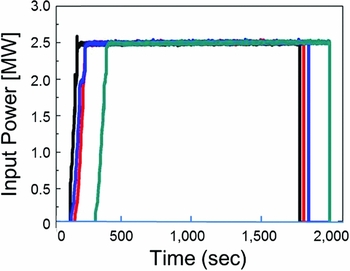
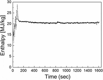
Figure 7 shows a variation of the input power for four separate discharges with the input current of 1,200 A and the air flow rate of 50 g/sec. The total power of 2.4 MW was maintained steadily for each discharge during 1,500 sec. Figure 8 shows a variation of the specific enthalpy at the torch exit corresponding to one of these discharges. Discharge with the specific enthalpy larger than 20 MJ/kg was also maintained steadily for 1,500 sec.
A variation of the input power for four separate discharges with the input current of 1,200 A and the air flow rate of 50 g/sec.

A variation of the specific enthalpy during 1,500 sec discharge.

4.0 ABLATION TEST OF THE THERMAL PROTECTION MATERIALS
Two candidate Carbon/Carbon (C/C) composites, which are currently under development and a graphite, were used in the ablation tests. The carbon/carbon composites are made from 3D-oriented carbon fibre preforms and a pitch-based carbon matrix; thus, their physical properties are isotropic. A needle-punched preform is used for CC-1 and a 3D rod preform is used for CC-2. The graphite is IG-15 and was provided by Toyo Tanso. Physical properties of these materials are summarised in Table 3.
Physical properties of the materials

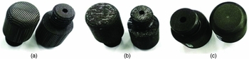
The materials are machined into cylindrical test samples with a diameter of 11 mm and a length of 20 mm, as shown in Fig. 9, to allow them to be installed in the arm of the substrate manipulation system of the plasma wind tunnel. The shape and size of the samples might impact the ablation process, but this will be studied in detail in the future.
Test samples: (a) CC-1, (b) CC-2 and (c) graphite.

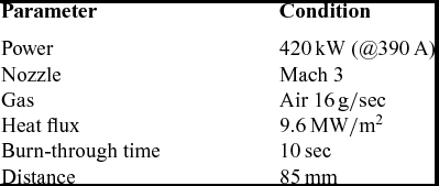
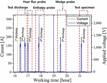
The conditions and experimental procedure for the ablation test are shown in Table 4 and Fig. 10. After test discharges, the heat flux, enthalpy and velocity of the discharge were measured. With a current of 390 A and an air flow rate of 16 g/sec, the enthalpy (12 MJ/kg) and the Mach number (3.07) were determined. After reaching the desired test conditions and calibrating the plasma flow, the test samples were immersed in the supersonic flow and the ablation tests were performed with a burn-through time of 10 sec. The test samples were located 85 cm from the nozzle tip and the heat flux was found to be 9.6 MW/m2.
Conditions of the ablation test

Experimental procedure for the ablation test.

A non-contact 3D surface measuring system (IFM G4, Alicona), a 0.1 mg-precise electronic balance, and a portable surface roughness tester (SJ-210, Mitutoyo) were used for pre-and post-test evaluation of the recession and mass loss of the test samples. A morphological analysis of the test samples was made with field emission scanning electron microscopy (FE-SEM; SU8030, Hitachi) that was equipped with energy-dispersive X-ray spectroscopy (EDS).
The ablation led to a shape change in the samples, causing them to become hemispherical. Recession of the surface led to mass loss of 0.496 g for CC-1, 0.722 g for CC-2 and 0.587 g for graphite, as shown in Table 5. The mass ablation rate of the lower density material (CC-1) is small compared to the samples with the higher density materials (CC-2 and graphite). Ablation led to an increase in the surface roughness; these changes are presented in Table 6. Before ablation testing, the roughness of the graphite is smaller than the roughness of the C/C composites. However, the roughness change in the graphite is the largest, which is attributed to the many small pores that are caused by sintering the graphite sample. Both the roughness of CC-1 before testing and the roughness change for CC-1 after testing are smaller than the corresponding values for CC-2; this is caused by the higher density and lower void content of CC-1.
Mass changes pre-/post-ablation for CC-1, CC-2 and graphite

Roughness changes pre-/post-ablation for CC-1, CC-2 and graphite

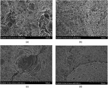
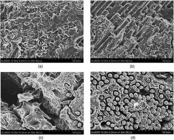
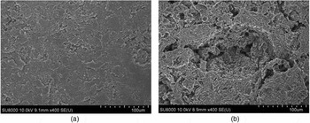
Figures 11–13 show pre- and post-test micrographs of the test samples. For CC-1, the image before the test shows that the carbon matrix is well infiltrated with carbon fibres and that there are no pores or cracks in the carbon matrix. After testing, we observe cracks only in the matrix region. For CC-2, some pores are observed in the carbon matrix before ablation testing. During the ablation, the pores grew, and many cracks which occurred at interface between the fibres and the matrix propagated. The carbon matrix disappeared after the test. For C/C composites, the shapes of the carbon fibres were also changed due to ablation from the edge since the dissociated carbon atoms in the C/C composite and oxygen in the plasma flow caused the thermochemical erosion. The pores, defects and the interfaces between the fibres and the matrix are oxidation active spots, so they oxidise first. Thus the CC-2 lost more matrix than the CC-1, which explains the ablation rate shown in Table 5. For the graphite, many small pores are distributed in the sample before the test; their size increased due to ablation or spilling during the test. The main difference in the ablation characteristics between the C/C composites and the graphite is that, for the C/C composites, the cracks occurred due to the difference in the thermal expansion coefficient between the carbon fibre and the carbon matrix, while for the graphite, ablation occurred without cracking.
Pre-ablation [(a), (b)] and post-ablation [(c), (d)] micrographs for the CC-1: (a), (c) for the carbon matrix and (b), (d) for the boundary between the carbon fibre and the carbon matrix.

Pre-ablation [(a), (b)] and post-ablation [(c), (d)] micrographs for the CC-2: (a), (c) for the carbon matrix and (b), (d) for the boundary between the carbon fibre and the carbon matrix.

Pre-ablation (a) and post-ablation (b) micrographs for the graphite.

5.0 SUMMARY
A high-enthalpy plasma wind tunnel with a power of 0.4 MW was constructed at CBNU for the development of thermal protection materials. These facilities will enable the study of plasma-surface interactions during space vehicle re-entry processes. Performance data suggest that the segmented arc plasma torch, which has been adopted as a plasma source at this facility, can produce a supersonic plasma flow with enthalpy greater than 10 MJ/kg; this is relevant for the thermal protection material testing under extreme conditions. Ablation characteristics of the two carbon/carbon composites and a graphite sample are investigated with the plasma wind tunnel. It is shown that the plasma wind tunnel, which contains extensive diagnostic and analytical tools, can be utilised in the development of new thermal protection materials.
ACKNOWLEDGEMENTS
This study was supported by a National Research Foundation (NRF) of Korea under contract 2014M1A3A3A03066611. This study was also supported by research facilities in the Plasma Application Institute of Chonbuk National University. The contributions of the members of the High-Enthalpy Plasma Research Center to the construction and commissioning of the plasma wind tunnel are gratefully acknowledged.