Nomenclature
- H th
-
height of inlet throat, mm
-
 $\Delta t$
-
time step, s
- u max
-
maximum velocity, m/s
-
$\Delta x$
-
cell’s characteristic length, mm
-
$CFL$
-
Courant–Friedrichs–Lewy number
-
$c$
-
speed of sound, m/s
- P 0
-
static of freestream, Pa
- P b
-
backpressure, Pa
-
$t$
-
time moment, s
-
$f$
-
frequency, Hz
-
${\textit{Ma}}$
-
Mach number
-
$L$
-
length, mm


Subscripts
- 0
-
of freestream
- 1
-
of freestream
- b
-
at the inlet exit
- th
-
at the inlet throat
1.0 Introduction
A supersonic inlet is a key component of a ramjet that captures and compresses air for the combustor at the desired airflow quality. Failure to start the inlet can lead to serious problems during the flight. Once the supersonic inlet undergoes unstart, there is a sharp decrease in the flow rate, total pressure recovery coefficient, and thrust. Moreover, the inlet unstart is likely to cause a combustor flameout that could destroy the whole engine structure [Reference Takasake, Brett and Fujimoto1]. Therefore, it is essential to avoid the inlet unstart phenomenon. Two major factors cause inlet unstart: the high internal contraction ratio and the abrupt increase in the downstream backpressure (which always happens as the required flow rate of the engine decreases).
Multiple experimental and numerical studies have investigated the inlet unstart characteristics caused by high backpressure. Saied Emami et al. [Reference Emami, Trexler and Auslender2] experimentally studied the unstart and restart process of inlets caused by backpressure variations for the flow with the Mach number of 4.0. They obtained the range of contractions for a successful ratio. Van Wie [Reference Van Wie, Kwok and Walsh3] reviewed the datasets in the literature and presented empirical curves of the limiting contraction ratios versus the different inlet conditions. The inlets with a high contraction ratio tended to exhibit “hard” unstart phenomena with considerable pressure losses in the combustor. However, “soft” unstarts occurred for inlets with low contraction ratios, where the unstart phenomenon occurred as flow mass venting [Reference Rodi, Emami and Trexler4]. Researchers have reported transient propagation unstart velocities of 26m/s [Reference Wagner, Valdivia and Yuceil5] and 55 to 70m/s [Reference Rodi, Emami and Trexler4]. The highly violent oscillatory mode of unstart resulted from approximately 124Hz [Reference Wagner, Valdivia and Yuceil5]. Maye and Paynter [Reference Mayer and Paynter6, Reference Mayer and Paynter7] developed an Euler analysis procedure for predicting the unstart tolerance of supersonic inlets. Trapier et al. [Reference Trapier, Duveau and Deck8–Reference Trapier, Deck and Duveau10] combined the experimental and computational approaches to perform a detailed analysis of the oscillations of inlet buzz shock waves. The algorithms for cumulative sum algorithms and the generalised likelihood ratio were applied to the unstart warning. The same algorithms were also used by Li et al. [Reference Li, Tan and Sun11]. Lee et al. [Reference Lee, Lee and Kim12] investigated the flow characteristics for rectangular and axisymmetric supersonic inlets and reported that the base frequencies for both models were at similar levels during the continuous buzz. Wooram [Reference Wooram and Chongam13] computationally examined the hysteretic inlet buzz under various mass flow conditions and explained hysteretic buzz and buzz transition mechanisms. Xie [Reference Xie and Guo14] investigated the restart performance of a mixed-compression supersonic inlet under the unstart condition caused by raising the backpressure. The hysteresis was eliminated by a pneumatic throat formed by shock wave–boundary layer interactions. Chen [Reference Chen15] reported that the moment of the port cover had a great influence on the inlet starting performance, and opening the port cover during inflation was conducive to inlet starting.
The inlet unstart state is usually accompanied by strong unsteady characteristics, such as remarkable shock wave motions and pressure fluctuations throughout the inlet channel. Previous studies have mainly focused on the influence of downstream mass flow choking and regular backpressure variations on the inlet start performance [Reference Xie and Guo14, Reference Tan, Sun and Yin16, Reference Meng, Zhu and Yan17]; however, most of these studies have ignored the impact of instantaneous high pressure within the downstream combustion chamber. It is very difficult for traditional backpressure simulation methods based on the mechanical blockage technique, such as a plug or a flap, to simulate the short-time pressurisation. Therefore, an unsteady numerical simulation technique was used to analyse the inlet start and unstart phenomena caused by sudden backpressure changes from the combustion chamber. Then, the unsteady flow field characteristics were explored.
2.0 Computational methods
2.1 Inlet geometry
Figure 1 shows the typical two-dimensional supersonic inlet model. External compression was achieved by three ramps inclined to the freestream direction by 8.5°, 16.5° and 25.5°. The internal surface of the cowl lip was inclined at 12.5° to the freestream direction. The inlet throat height is expressed as H th, and H th dimensionalises other geometrical parameters of the inlet. The length and offset ratios of the diffuser were 9.4H th and 0.79H th, respectively; there was abrupt turning at the exit. The self-starting and designed Mach numbers of the inlet were 2.4 and 3.3. Table 1 shows the freestream conditions.
Model of the inlet.

2.2 Numerical approach
The commercial CFD software ANSYS Fluent was employed for the numerical calculations. Fluent solves the Reynolds-averaged Navier–Stokes equations in a finite-volume framework. As the flow flow velocity in the test is relatively high, the compressible density-based flow solver is selected. The N-S equations are discretised by a second-order upwind scheme and the turbulent viscosity is resolved by the k–ω shear stress transport turbulent model. Roe’s method was used as the inviscid flux scheme. The simulated fluids were treated as a compressible ideal gas with standard air composition. The Sutherland’s formulation was adopted to calculate the molecular viscosity of the gas. The pressure far-field and pressure-outlet boundary conditions were applied, and a nonslip adiabatic boundary condition was employed for all the wall surfaces. The backpressure variations were implemented by a user-defined function. Unsteady calculations were based on the flow fields obtained from the initial steady calculation.
2.2.1 Simulation validation
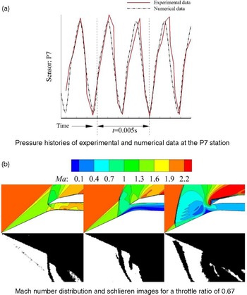
To demonstrate the reliability of the computational fluid dynamics (CFD) data, we validated the turbulent model and the numerical methods introduced in the previous section against the existing experimental data published in the literature that dealt with the buzz problems in the supersonic axisymmetric inlet [Reference Nagashima, Obokata and Asanuma18]. The Mach number was 2; the Reynold number was approximately 107, and the reference length of the inlet diameter was 60mm. We chose the second example for the simulation in which the throttle ratio was 0.67. Figure 2(a) gives the static pressure histories of the experimental and numerical methods at the P7 station. Figure 2(b) gives the flowfield schlieren measured during the test and those obtained by computations. The numerical results of the pressure histories and shock wave structures demonstrate good consistency with the experimental results.
2.2.2 Grid-sensitivity analysis
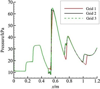
It is important and necessary to ensure that the obtained CFD results are grid-independent. Three sets of grids with various densities (grid 1 = 1.1 × 10⁵; grid 2 = 1.7 × 10⁵, grid 3 = 2.5 × 10⁵) were used. Figure 3 shows the results obtained with different meshes. There are slight differences between the grid 2 and the grid 3 results, which proves the grid independence. However, the grid 1 shows a large deviation. Therefore, grid 2 was chosen for numerical investigations in this paper. To fulfill the mesh quality requirements of the near-wall models used to resolve the flows, we used the dimensionless distance y + of the wall-adjacent nodes, which was approximately 1.0.
2.2.3 Time step sensitivity analysis
In an unsteady computational domain, the size of the time step directly affects the accuracy of the calculation. Therefore, it is essential to select an appropriate time step size that can resolve the flow domain. The time step is estimated by the following equation [Reference Neophyton, Mastorakos and Cant19]:
 \begin{align}\Delta t{\rm{\;}} = \frac{{\Delta x}}{{\left( {c + {u_{{\rm{max}}}}} \right)}}CFL,\end{align}
where
 $\Delta x$
is the cell’s characteristic length, and u
max is the maximum velocity in the flow field.
 $CFL$
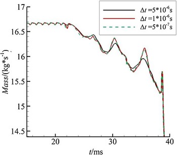
, which is the Courant–Friedrichs–Lewy number, equals 0.6. According to [Reference Takasake, Brett and Fujimoto1], the time step is 1 × 10⁻⁶s. To assess the step sensitivity in this paper, we evaluated three sequences of grid sizes, namely, 5 × 10⁻⁶s, 1 × 10⁻⁶s and 5 × 10⁻⁷s. The implicit time discretisation method is adopted, and 200 steps are iterated within a single time step to ensure the convergence of the transient flow field at each time step. Figure 4 shows the flow histories of the throat calculated under different step times. All the time step sizes show a similar trend; however, the results of the 1 × 10⁻⁶s and 5 × 10⁻⁷s sizes were almost the same. The results become step non-sensitive when the step size of 1 × 10⁻⁶s. Then, the time step size of 1 × 10⁻⁶s is chosen.
Freestream conditions for simulation

Pressure distribution and flow structure.

Pressure distribution on the ramp and the diffuser surface.

Throat flow history calculated under different step time.

3.0 Results and discussion
3.1 Unstart and restart characteristics of an inlet under the design condition
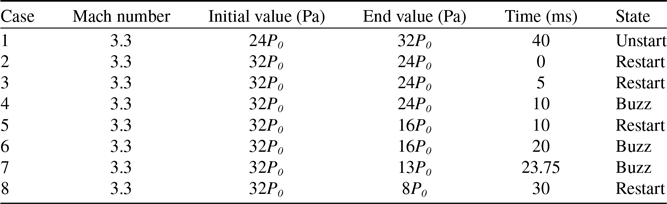
To examine the effects of the depressurisation time and value on the inlet unstart and restart characteristics under the design condition, we performed simulations with eight backpressure variation modes (see Table 2) with P 0 = 5529.3Pa. The simulations initially started from P b = 24P 0 at which the inlet was under normal operating conditions. The backpressure was increased to 32P 0 within 40ms until the inlet switched to a typical unstart state. Then, seven kinds of depressurisations were simulated.
Backpressure change mode under design conditions

Throat flow history of Case 1.

Pressure distributions of the ramp wall at the A, B, C, and D moments time points.

3.1.1 Unstart flow field under rapid pressurisation
To obtain a typical unstart flow field, we conducted an unsteady simulation based on backpressure ranging from 24P 0 to 32P 0 within 40ms. The backpressure increased linearly with time for simplifying the pressurisation process, as follows:
 \begin{align}{P_b} = {P_0}*\left( {24 + 200 \ast t} \right).\end{align}
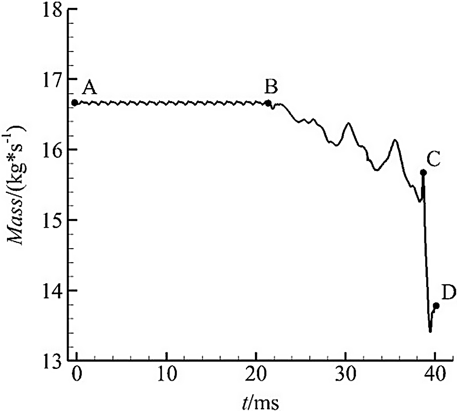
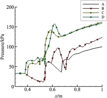
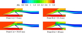
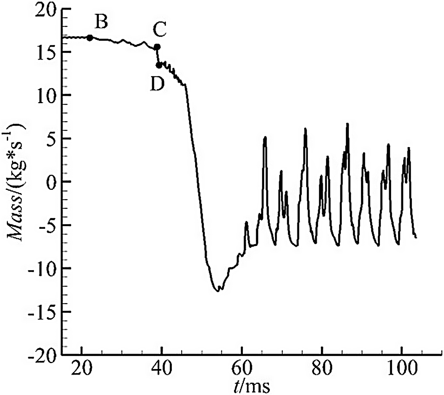
The throat flow history under the pressurisation process is presented in Fig. 5. From Fig. 5, it is clear that the unstart process can be divided into three stages: AB, BC and CD. Figures 6 and 7 show the pressure distributions of the ramp wall and the Mach number contours of the inlet at the four moments A, B, C and D. Using the results in Figs. 5–7, we describe the flow characteristics of the unstart process.
Mach number contours of the inlet.

Throat flow history of Case 2.

Initially, the inlet works in the supercritical state in the AB stage. The first shock wave is located downstream of the throat, and the throat flow is constant. The first shock wave is pushed through the throat as the backpressure increases. The throat flow decreases slightly under the combined action of the airflow separation on the ramp wall and the cavity. After the C moment (see Fig. 5), the first shock wave is pushed out of the lip and appears as an X-shaped wave. Airflow spillage occurs at the lip, and the throat flow decreases rapidly. The typical unstart flow field is established.
3.1.2 Effects of depressurisation time on restart
Based on the simulated unstart flow field in the last section, we investigated the influence of different depressurisation speeds on inlet restart characteristics. The depressurisation process was also linear.
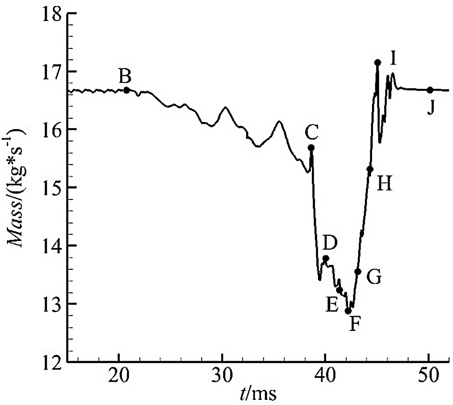
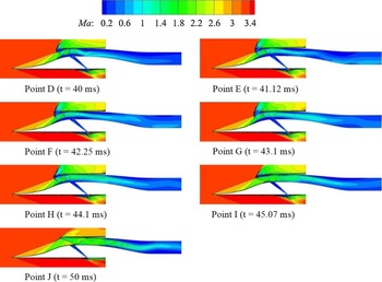
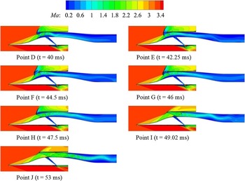
Figures 8–11. show the throat flow histories of Cases 2 and 3; they also show the Mach number contours of the inlet at different moments. The two kinds of throat flow histories show that the flow begins to rise (stage FI) after a period of decline (stage DF), and the inlet finally restarts. The throat flow histories of the two depressurisation methods are almost similar. However, the flow decline (stage DF) and the time of flow recovery (stage FI) in Case 3 were greater than those in Case 2. The minimum throat flow in Case 3 was smaller than that in Case 2. This took more time to propagate the downstream pressure signal to upstream in Case 3.
Mach number contours of the typical moments of Case 2.

Throat flow history of Case 3.

Mach number contours of the typical moments of Case 3.

According to the Mach number contours, the flow fields of the inlet restart process were approximately the same for the two cases. The detached shock and the airflow separation on the external contraction surface moved upstream from the D moment to the F moment moved upstream because of the high pressure. At the F moment, the shock wave was located at the upstream position. Then, the lower pressure signal reached upstream. Simultaneously, the detached shock wave moved downstream, and the separation bubble shrank; the entering airflow rate also increased. Finally, the external compression shock system was reestablished, and the inlet restarted.
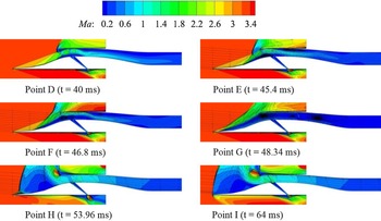
Figure 12 shows the throat flow history of Case 4. Clearly, the inlet remains in the unstart state even if the backpressure drops to normal working conditions. From the Mach number contours in Fig. 13, the flow patterns can be divided into four stages: DE, EG, GH and HI.
Throat flow history of Case 4.

Mach number contours of the typical moments of Case 4.

Throat flow history of Case 5.

Throat flow history of Case 6.

Throat flow history of Case 7.

Throat flow history of Case 8.

The DE stage of Case 4 is similar to the DF stage of Case 3, except that the airflow spillage is larger for the DE stage. After the E moment, the shock wave at the internal contraction section is pushed out of the lip, and the separation bubble moves forward to the second compression surface. At the G moment, the throat flow decreases to zero, and the separation bubble occupies most of the inlet entrance. Then, the backpressure is close to the ending value of 24P 0 , greater than the pressurisation value from the normal shock. Consequently, a reverse flow forms, and the buzz starts.
Our discussions clearly show that the backpressure drops from the inlet unstart value to the normal working value. The inlet becomes easier to restart with the decrease in the depressurisation time. However, the inlet cannot restart if the depressurisation time is too long. The depressurisation time by fuel reduction in the combustion chamber will not be as short as the setting value of 5ms. Therefore, different depressurisation values were specified to study the restart characteristics, as shown in Cases 5–8 in Table 2.
3.1.3 Effects of depressurisation value on the restart
Figures 14–15 show the throat flow histories of Cases 5 and 6. The inlet can restart when the depressurisation time is 10ms; however, it stays in the unstart state when it is 20ms. A comparison of Cases 5 and 6 with those of Case 3 shows that the maximum depressurisation time in which the inlet can restart increases with the depressurisation range.
When the depressurisation time is too large, the inlet cannot restart (Cases 4 and 6). This is because the final backpressure of the inlet is greater than the pressurisation value from the shock induced by the separation. Therefore, Cases 7 and 8 are set to determine whether the inlet can restart when the backpressure drops continually; the depressurisation speeds here are the same as those for Cases 4 and 6.
Figure 16 shows the throat flow history of Case 7. A buzz starts when the backpressure drops to 13P 0 . Figure 17 shows the throat flow history of Case 8, which is similar to that of Case 7 in which there was a short buzz start when the backpressure dropped to 8P 0 . However, after a period of buzz, the inlet could restart.
Backpressure change modes under start condition

Typical unstart Mach number contour.

Throat flow history of Case 10.

Throat flow history of Case 11.

Throat flow history of Case 12.

Throat flow history of Case 13.

Instantaneous mass flow of the inlet throat for one buzz in Case 7.

Pressure histories of different points in the diffuser during one buzz for Case 7.

Mach number contours and streamlines for typical points in Fig. 23.

3.2 Unstart and restart characteristics of an inlet under start incoming flow condition
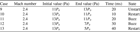
To examine the effects of the depressurisation time and depressurisation value on the inlet unstart and restart characteristics under the start incoming flow condition, we performed simulations with five backpressure variation modes (see Table 3), where P 0 = 54048 Pa. Similar to the previous research methods, the unstart flow field of the inlet was simulated first. Then, the depressurisation processes were conducted.
Instantaneous mass flow of the inlet throat during one buzz for Case 12.

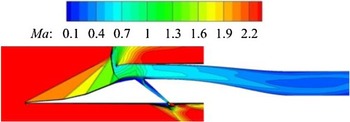
Figure 18 shows the final unstart Mach number contour of Case 9. In this case, the unstart flow field’s characteristics are different from those in Case 1. For example, the number of separation zones in front of the inlet lip, and the λ-type detached shock waves are different.
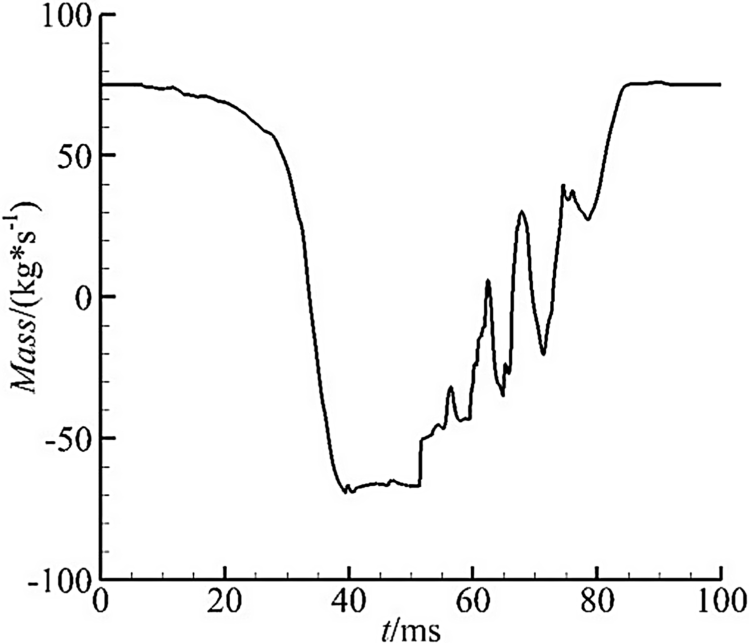
Figures 19 and 20 show the throat flow history of Cases 10 and 11. The inlet can restart when the depressurisation time is 10ms whereas the inlet remains in the unstart state when the time is 20ms. This feature is similar to the restart characteristics under the design conditions. Figure 21 gives the throat flow history of Case 12. Similarly, a buzz starts when the backpressure drops to a slightly bigger value than the pressurisation value from the normal shock. Figure 22 shows the throat flow history of Case 13. The inlet achieves restart after a period of buzz.
According to the earlier investigations, the inlet can restart by increasing the depressurisation range when the big buzz occurs. The final backpressure value is lower than the pressurisation value from the normal shock in a certain incoming Mach number, such as the end value in Cases 8 and 13.
3.3 Inlet buzz
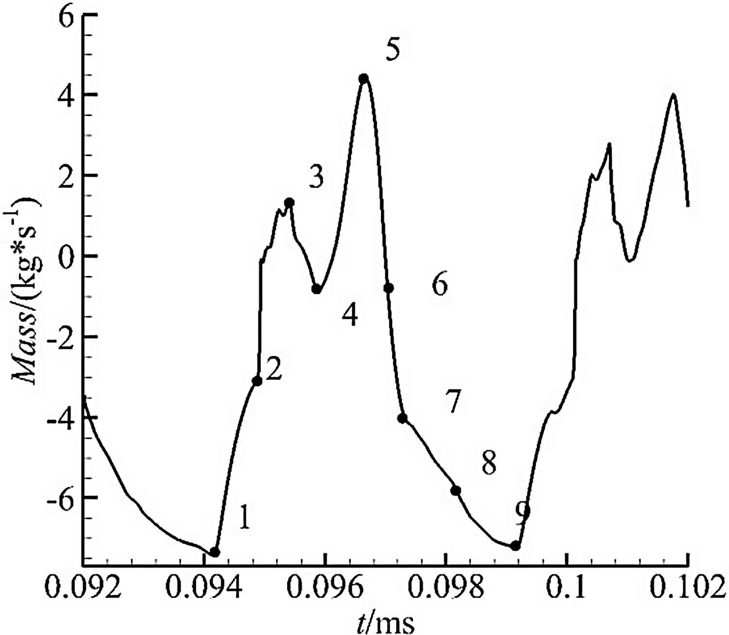
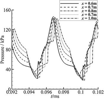
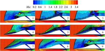
The unstart flowfield is invariably accompanied by buzz; therefore, the buzz flowfields are further investigated to obtain deeper insights into the buzz under such instantaneous backpressure change. Figure 23 shows the instantaneous mass flow at the inlet throat during a buzz for Case 7. Figure 24 shows the pressure histories of different points in the diffuser. Figure 25 shows the Mach number contours and streamlines of the typical points shown in Fig. 23. From these results, the buzz cycle can be categorised into two phases.
Mach number contour and streamlines for typical points in Fig. 26.

The frequency spectrum of throat mass for Case 7.

The frequency spectrum of throat mass for Case 12.

In Phase 1 (from point 1 to point 5), the pressure inside the inlet diffuser is sufficiently low because of the long-time reverse flow; therefore, the shock moves downstream, and the inlet swallows the old separated area. Therefore, the incoming mass flow and the pressure in the diffuser increase. At the same time, a new separation develops at the shock foot. The separated area increases as the shock wave move downstream until it occupies all the compression ramps.
In Phase 2 (from point 5 to point 9), the oblique shock moves upstream because of the high pressure inside the inlet. Consequently, airflow spillage increases, and the mass flow rate decreases to zero (point 7); then, a reverse flow occurs. The oblique shock wave angle increases gradually because of the increase in the reverse flow. Simultaneously, the downstream pressure decreases and a newly separated area forms by the interaction of the incoming flow and the reverse flow (point 9), identical to point 1. Then, a new buzz cycle begins.
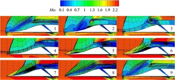
Similar buzz flows were found in Case 12. The motion of the normal shock and the large separation on the compression ramps are shown in Figs. 26 and 27. The inlet buzz was accompanied by the separation variations at the shock foot.
The buzz mechanism can be classified as Dailey-type buzz [Reference Dailey20] in which the buzz is triggered by the obstruction caused by the separation on the compression surface. The minor difference between the two kinds of buzz waves is that the reflux time of Case 7 is longer than that of Case 12. Also, the large separated area formed by the interaction of the incoming flow and the reverse flow is generated only for Case 7. These differences might have resulted from the different boundary conditions.
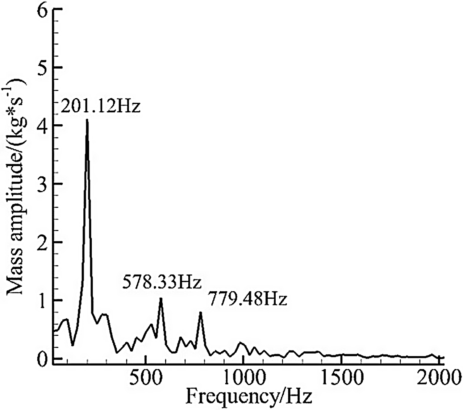
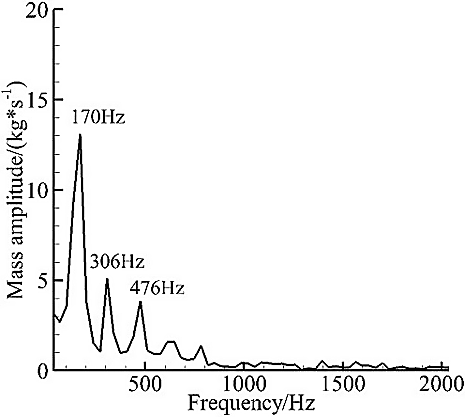
Figures 28 and 29 show the frequency spectrum results for the throat mass for Case 7 and 12. The main frequencies of the inlet buzz were 201.12Hz for Case 7 and 170Hz for Case 12. The fundamental acoustic modes for a duct with open and closed ends are estimated as follows [Reference Newsome21]:
 \begin{align}f = \left( {2{\rm{n}} + 1} \right)\frac{{c\!\left( {1 - {{\left( {Ma} \right)}^2}} \right)}}{{4L}}\;n = 0,1,2, \ldots, \end{align}
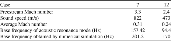
where L (=1.18m) denotes the distance between the cowl lip and inlet out. Ma is the average Mach number of the diffuser, and c is the speed of sound. The simulation results showed that the mean Ma values were 0.31 for Case 7 and 0.24 for Case 12, and the mean c values were 822m/s for Case 7 and 473m/s for Case 12. The calculated fundamental frequencies were 157.42Hz for Case 7 and 86Hz for Case 12. Compared with the frequency spectrum results, the fundamental frequencies of the acoustic resonance modes were less than the base frequencies obtained by simulations (see Table 4). Other studies observed similar phenomena [Reference Rodi, Emami and Trexler4, Reference Trapier, Deck and Duveau10, Reference Hawkins and Marquart22]. We inferred that the disturbances that originated from the separation bubble made the base frequency different from the acoustic resonance of the inlet duct.
Base frequencies of the buzz obtained using the formula and simulation

4.0 Conclusions
This research investigated the unstart and restart characteristics of a two-dimensional supersonic inlet with abrupt backpressure variations. Using thirteen modes of backpressure changes, we reached the following conclusions. The main conclusions are as follows:
The flow field characteristics under the typical unstart phenomenon have two aspects: (i) a decrease in the effective cross-section area of the throat, and (ii) the flow spillage in front of the lip. Consequently, the backpressure-resistance ability of the inlet decreases. As the backpressure rapidly falls to the value of the normal working state, the inlet can restart; otherwise, the detached shock wave located in front of the lip is pushed upstream until a detached bow shock forms in front of the compression ramps. Then, the inlet sinks into a deep unstart even though the backpressure is close to the normal working value.
Comparing the results obtained from the different depressurisation modes, we found that when depressurisation time is short, it is easier for the inlet to restart at the same depressurisation value. When the depressurisation value is high, the maximum depressurisation time of the inlet takes longer to restart. However, a big buzz generates if the depressurisation time is too long. With the continuing reduction in the backpressure to a low value, the inlet in the deep unstart state can restart after a buzz period. The backpressure value is lower than the pressurisation value from the normal shock for a certain incoming Mach number; otherwise, the inlet enters a long buzz state.
The separation bubble that develops at the shock foot on the compression ramps is mainly responsible for the appearance of a big buzz; this bubble also plays an important role in determining the basic frequency of the buzz.
Acknowledgements
This work is supported by the National Natural Science Foundation of China (Nos. 51906104, 12025202, U20A2070), National Science and Technology Major Project (2019-II-0014-0035), Natural Science Foundation of Jiangsu province (BK20190385), Jiangsu provincial 333 high-level talent cultivation project (Grant No: BRA2018031), the special scientific research project for commercial aircraft, the 1912 project (Grant No. 2019-JCJQ-DA-001-067), the priority academic program development of Jiangsu higher education institutions.