
 NPR



1. Introduction
The Coanda effect, where a fluid flow adheres to an adjacent surface, is extensively employed in active flow control across numerous fields. In aviation, this principle is crucial for augmenting aerodynamic performance. For instance, applying a thin Coanda jet along the suction surface of a fixed-wing aircraft’s aerofoil boosts lift by counteracting boundary layer separation (Yoshida et al. Reference Yoshida, Ikemori and Takahashi2013; Jie et al. Reference Li, Xu and Pei2017). This effect is also integral to advanced aerospace concepts, such as the rudderless stealth unmanned aerial vehicle outlined in DARPA’s CRANE (Control of Revolutionary Aircraft with Novel Effectors) programme (Gray et al. Reference Gregory-Smith and Gilchrist2023), where jet generators positioned at the curved tail sections of conventional control surfaces generate necessary control torque (Zhang & Zhao Reference Zhang and Zhao2023; Zhang et al. Reference Zhang, Huang, Zhu, Gao, Chen, Wu and He2023). Furthermore, within engine exhaust systems, Coanda jets enable thrust vectoring through the active guidance of exhaust gases (Warsop et al. Reference Warsop, Crowther and Forster2019; Nayebi & Taeibi Rahni Reference Nayebi and Taeibi Rahni2024). Beyond aerospace applications, this established flow control method has been effectively adapted for use in marine vessels (Xu et al. Reference Xu, Su, Bensow and Krajnovic2022, Reference Xu, Su, Bensow and Krajnovic2023; Matías-García et al. Reference Cornelius and Lucius2023), submersible systems (Li et al. Reference Li, Liu, Wang and Ren2022), the energy sector (Shi et al. Reference Shi, Gu, Zhou, Wang, Feng and Li2022; Alhaddad et al. Reference Alhaddad, Mehta and Helmons2023; Zhao et al. Reference Zhao, An and Lei2023), medical research (Saceleanu et al. Reference Saceleanu, Covache-Busuioc, Glavan, Corlatescu and Ciurea2023; Toader et al. Reference Toader, Rădoi, Aljboor, Glavan, Covache-Busuioc, Ilie and Ciurea2024), and various other interdisciplinary areas.
When a fluid passes along a curved solid boundary, its acceleration near the wall results in a reduction of static pressure. According to the Bernoulli principle, an increase in fluid velocity leads to a greater pressure differential between the free stream and the wall surface, which promotes flow adherence to the curved contour (Abramson & Rogers Reference Abramson and Rogers1983). Simultaneously, the curved path of the fluid generates centrifugal forces; in classical mechanics, the magnitude of these forces is proportional to the square of the velocity, and inversely related to the radius of curvature (Alexander et al. Reference Alexander, Harris, Spoor, Boyland, Farrell and Raines2016). A continual rise in the supply pressure or change of the wall’s curvature can eventually overcome the flow’s ability to remain attached, leading to its detachment from the wall surface (Reba Reference Reba1966). For high-speed, high-altitude flight vehicles and supersonic thrust nozzles, the need for circulation control is amplified. Yet the low static pressure environment characteristic of high altitudes or high-speed flow leads to weaker wall-normal pressure gradient. Consequently, the flow attached to the wall becomes prone to detachment, thereby degrading the performance of circulation control systems (Cornelius & Lucius Reference Forster and Steijl1994). Consequently, it is imperative to exhaust all possible means to enhance the attachment characteristics of the airflow over the curved surface, and maximise the Coanda effect. This necessitates a thorough investigation into the underlying mechanisms governing flow attachment from a fundamental perspective.
This paper primarily focuses on the jet-induced Coanda effect within active flow control technologies. The sustained attachment of a jet is governed by a critical balance between the radial pressure gradient (∂P/∂r) and the centrifugal force (ρU
j
2/r) arising from the flow’s curved path. In subsonic jet flows, which typically occur at relatively lower nozzle pressure ratio (
 $\textit{NPR}$
, which is the ratio of the jet supply total pressure to the ambient pressure), the jet generally remains attached to the surface. Detachment under these conditions is uncommon unless the surface exhibits an extremely small radius of curvature. However, as
 $\textit{NPR}$
increases beyond a specific threshold, the flow at the jet outlet becomes underexpanded, leading to the formation of a supersonic jet. This introduces complex flow structures, including oblique shock waves, expansion fans, strong shear layer and separation bubbles (Zhao et al. Reference Zhao, Wang, Li, Qin and Pan2024). The pressure gradient responsible for maintaining attachment is influenced by two primary factors: the local static pressure on the wall, and the developmental thickness of the effective jet shear layer. Concurrently, the centrifugal force, which promotes detachment, is a function of the local fluid density and velocity. As
 $\textit{NPR}$
rises, these two forces do not increase at the same rate; the centrifugal force typically grows more rapidly than the restraining pressure gradient. This divergent growth leads to a point of instability where the centrifugal force ultimately exceeds the pressure gradient, triggering a sudden detachment of the jet from the wall (Bevilaqua & Lee Reference Bevilaqua and Lee1984), and the critical
 $\textit{NPR}$
is named detachment
 $\textit{NPR}$
(denoted
 $\textit{NPR}$
d
). When the jet reminds detached flow, decreasing
 $\textit{NPR}$
would bend the flow to the curved wall again. The
 $\textit{NPR}$
value corresponding to the reattachment process is called reattachment
 $\textit{NPR}$
(denoted
 $\textit{NPR}$
r
). Typically, reattachment
 $\textit{NPR}$
is lower than detachment
 $\textit{NPR}$
, which produces a hysteresis zone/area for the Coanda jet (Shi et al. Reference Shi, Luo and Zhu2022; Wang et al. Reference Wang, Qu, Zhao and Bai2022).
To enhance the Coanda effect, it is essential to conduct research encompassing both attachment characteristics and the hysteresis phenomenon. Various strategies have been developed that aim to lower the static pressure near the wall – given that ambient pressure remains constant. One effective approach involves redesigning the geometry of jet generators, which helps to raise the threshold at which detachment occurs, and optimises the adherence of the jet. Introducing a step near the jet outlet has also proven beneficial; this configuration shortens shock cell structures and shrinks separation zones, thereby actively delaying jet detachment from the Coanda surface; see Gregory-Smith & Senior (Reference He and Zhang1994), Wang et al. (Reference Wang, Qu, Zhao and Bai2022) and Penty Geraets et al. (Reference Penty Geraets, Crowther, Quinn, Weigert, Shearwood, Nabawy and Axani2023). Their results have also indicated that the effect of step height decreases with much greater step height. However, they did not give the optimal step height to reach the relatively maximum detachment
 $\textit{NPR}$
. Therefore, it is necessary to obtain accurate and reliable data through effective experimental approaches to demonstrate the existence of an optimal step height, and furthermore, to derive an empirical correlation for predicting this optimal step height. Additionally, reducing the curvature of the Coanda surface alleviates centrifugal forces, diminishing the pressure differential required to maintain attachment and effectively increasing
 $\textit{NPR}$
at which separation initiates (Penty Geraets et al. Reference Penty Geraets, Crowther, Quinn, Weigert, Shearwood, Nabawy and Axani2023). In high-speed free-stream conditions, injecting a low-speed secondary jet above the primary Coanda jet has been shown to stabilise the pressure field surrounding the primary jet. This stabilisation enhances expansion effects, suppresses separation bubble formation, and contributes to delayed jet detachment. It should be noted, however, that this beneficial effect becomes less pronounced under low free-stream velocity conditions, where the pressure of the secondary jet may fall below ambient levels, reducing the critical pressure advantage (Li et al. Reference Liepmann and Roshko2023). From a design perspective, the majority of high-
 $\textit{NPR}$
jet nozzles employ a converging slot design due to manufacturing practicality; however, these tend to achieve lower attachment efficiency compared to converging–diverging nozzles. The latter design maintains higher flow velocities and lower pressures both inside and at the exit of the nozzle, creating more favourable conditions for jet attachment (Forster & Steijl Reference Gray, Uleck, Feldstein, Kangas, Beckman, Florence and Woszidlo2017). Active control methods are able to improve the attachment performance of a Coanda jet, e.g. using a rotating Coanda wall (Zhao et al. Reference Zhao, Wang, Li, Huang, Qin and Pan2025) so as to enhance the jet’s ability to resist detachment.
While numerous passive and active control techniques have been implemented to enhance the attachment characteristics of Coanda jets, several issues warrant further investigation, e.g. the determination of the optimal step height. In this study, we will expand the understanding of using a step to control the detachment processes of a Coanda jet – a topic seldom addressed in the open literature, particularly regarding the optimal step height. The paper is structured as follows. Section 2 describes the experimental method and testing facilities. Section 3 analyses the pressure and flow visualisation results. Finally, conclusions are given in § 4.
2. Experimental set-up
This section presents the testing model, the air supply system and the measurement facilities.
2.1. The Coanda jet model
The schematic of the experimental model is illustrated in figure 1. The left-hand part of the model is connected to a gas source with maximum regulated pressure 1 MPa. A total pressure tube is installed in the left-hand converging chamber to monitor the total pressure of the feeding gas. Two steel meshes are mounted downstream of pressure tube 1 to homogenise the incoming flow and to break large vortices. Another converging chamber is connected to the steel mesh as a transition channel to meet the narrow jet outlet. The upper plate of the chamber can be alternated to adjust the jet outlet height h. A semi-cylindrical Coanda surface is installed on a displacement platform at the jet outlet; the width of the Coanda wall is 80 mm, and the radius is r. The step height s is defined as the distance between the jet nozzle’s lower lip and the curved surface. The displacement platform allows movement of the Coanda wall along the vertical direction; thereafter, the step height s is changed, where the positioning accuracy is ±0.01 mm. Another total pressure tube is installed 400 mm away from the jet outlet to monitor the jet detachment. Both pressure tubes are connected to pressure transducers (with natural frequency 2 MHz); the signal is recorded by a data acquisition device with sampling rate 4000 Hz, and the pressure measurement accuracy is approximately 0.1 % of the full scale.
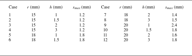
Geometric parameters of the testing model.

Table 1. Long description
The table presents geometric parameters of a testing model, organized into two sections with six cases each. Each section lists cases with corresponding values for radius (r) in millimeters, height (h) in millimeters, and maximum displacement (smax) in millimeters. The first section includes cases 1 to 6 with radius values ranging from 15 to 18 millimeters, heights from 1 to 3 millimeters, and maximum displacements from 1.2 to 1.8 millimeters. The second section includes cases 7 to 12 with radius values ranging from 18 to 20 millimeters, heights from 2 to 3 millimeters, and maximum displacements from 1.4 to 2.4 millimeters. Each row provides specific measurements for each case, detailing the geometric parameters used in the testing model.
Schematic of the testing model.

Table 1 presents the main parameters considered in this study. The feeding pressure is increased from environmental pressure to the status that the Coanda jet is separated from the wall, and s max is defined as the maximum variation in step height. The radius of the Coanda surface r was determined by the field of view of the schlieren system and the resolution of the high-speed camera. A radius that is too large would prevent the camera from capturing the flow region of interest, whereas a radius that is too small would result in insufficient clarity of the flow structures. The height of the jet slot h was referenced from existing literature, maintaining the ratio h/r at approximately 10. The step height s is adjustable via a displacement platform. The actual maximum height (s max in table 1) was determined experimentally based on the specific flow conditions.
2.2. Measurement facilities and experimental procedures
Figure 2 illustrates the experimental set-up employed for simultaneous pressure measurement and flow visualisation. The pressure transducers, which operate on the principle of converting the deformation of an internal elastic element into an electrical signal via a Wheatstone bridge configuration, translate the instantaneous fluid pressure into a proportional 0–10 V DC voltage output. This analogue voltage signal is subsequently captured and digitised by a data acquisition system, utilising a high sampling frequency 4 kHz to ensure the resolution of transient pressure dynamics
(a) Schematic of the testing platform, and (b) photo of the platform.

The flow field is visualised using a schlieren system comprising a light source, convex lens, slit, two plane mirrors, two concave mirrors, a knife edge and a high-speed camera. By adjusting the knife edge, the schlieren system is shifted to a shadowgraph system (Settles & Hargather Reference Settles and Hargather2017). The light source is a 100 W incandescent bulb operated at ∼ 30 W in this study. The 75 mm diameter concave mirror defines the field of view. The camera features a 384 pixel × 232 pixel resolution, 45 188 Hz sampling frequency, and 1 μs exposure time. A recognised limitation of the optical diagnostics employed in this study is the loss of volumetric information due to path integration. Since the measured intensity is an accumulation of density gradients (for schlieren) and Laplacians (for shadowgraph) along the entire light path, the resulting data lack depth resolution. This means that complex three-dimensional flow topologies, such as streamwise vortices or spanwise instabilities, are integrated into a single plane, potentially leading to an oversimplification of the flow physics.
The experimental procedure is as follows. First, the geometric parameters of the model (r,h,s) are set. Then
 $\textit{NPR}$
is continuously increased until the jet detaches from the Coanda wall, while simultaneously recording schlieren/shadowgraph images of the detachment process and the corresponding detachment
 $\textit{NPR}$
. During the testing, room temperature varied between 296.25 K and 300 K, and room pressure ranged from 95.51 kPa to 96.06 kPa. An example of pressure data from tubes 1 and 2 is presented in figure 3. When the Coanda jet detaches from the wall, it impinges on tube 2 (figure 3). The sudden pressure rise (the red solid line in figure 3) indicates the precise moment of jet detachment, and the corresponding feeding pressure is identified from the black solid line.
Example of determining the detachment
 $\textit{NPR}$
through pressure signals (case 11, h = 0 mm).

Figure 3. Long description
A line graph displays pressure measurements over time for two different pressure tubes. The horizontal axis represents time in seconds, ranging from 0 to 20 seconds. The left vertical axis represents the pressure in tube 1 in kilopascals (kPa), ranging from 0 to 700 kPa. The right vertical axis represents the pressure in tube 2 in kPa, ranging from 80 to 120 kPa. Two data lines are plotted: one for pressure tube 1 (black line) and one for pressure tube 2 (red line). The black line shows a significant increase in pressure, peaking around 600 kPa, followed by a sharp decrease and stabilization around 100 kPa. The red line remains relatively stable around 100 kPa with minor fluctuations. Annotations indicate points of detachment detection and jet impingement on tube 2. An inset image shows a close-up of tube 2 with the jet impinging on it.
3. Detachment
 $\textit{NPR}$
measurement and analysis

As
 $\textit{NPR}$
increases continuously from the initial state, the jet transitions from subsonic to supersonic flow, and the inner flow structures change drastically. This study mainly focuses on the supersonic status because the jet separation happens in the supersonic realm here. The typical flow structures are shown in figure 4, where the jet slot height is marked by h, the step height is marked by s, the change of step height is marked by Δs, r is the radius of Coanda wall, θ is the azimuthal angle, l is the length of the circular arc, Δr is the increased radius caused by the increased step Δs, P
0 is the total pressure of the feeding gas, P
e
is the pressure of the environment, P
 ${w\textit{all}}$
(θ) is the wall static pressure at θ, and I–III represents the possible vortices.
Typical flow field structures of a supersonic Coanda jet.

Figure 4. Long description
A diagram of the flow structures of a supersonic Coanda jet. The diagram shows the interaction between various flow components and forces. Key elements include the initial pressure (P0), shear layer, expansion wave, shock wave, slip line, and Coanda wall. The increased step and the radial distance (r) are also marked. The diagram illustrates the formation of oblique shock waves, expansion fans, and separation bubbles. The pressure gradient and centrifugal force are depicted as influencing the attachment and detachment of the jet. The local static pressure on the wall and the developmental thickness of the effective jet shear layer are shown as primary factors affecting the pressure gradient. The centrifugal force, which promotes detachment, is a function of the local fluid density and velocity. The diagram highlights the point of instability where the centrifugal force exceeds the pressure gradient, leading to jet detachment. The reattachment process is also illustrated, showing the hysteresis zone for the Coanda jet.
The jet slot experiences an underexpanded flow condition when the internal
 $\textit{NPR}$
is relatively higher. As the exit pressure is higher than the ambient pressure, the flow expands to match the environmental pressure. More complicated flow structures are produced with varying
 $\textit{NPR}$
and geometric parameters. Detailed explanations of underexpanded jet flows are provided by Zucrow & Hoffman (Reference Zucrow and Hoffman1977) and Liepmann & Roshko (Reference Llopis-Pascual2001). For a Coanda jet model with a step, the flow pattern is more complex due to the asymmetry of the upper and lower jet boundaries caused by bending, the formation of recirculation areas, and differences in shock wave position and intensity. The shock cell is stretched and deformed, especially the first cell. Its lower boundary shears with the upper boundary of the recirculation area, generating at least one vortex (shown in figure 4). Meanwhile, a stronger incident shock wave may induce boundary layer separation and elevate the local wall static pressure. Since the wall normal pressure gradient
 $\partial P/\partial r$
is the main fact that puts the jet on the curved wall, the local flow separation on the wall can easily cause the jet to detach from the Coanda wall (Llopis-Pascual Reference Matías-García, Bardera, Barroso and Franchini2016). When the step height s is increased, the semicircular wall shifts downwards (blue solid curve in figure 4), which in return affects the intensity of the recirculation area, the strength of the shear layer, the position of the incident shock wave impingement point (marked by A and B in figure 4), and the wall pressure distribution (P
 ${w\textit{all}}$
(θ) in figure 4). Additionally, the detachment
 $\textit{NPR}$
corresponding to the jet also changes.
Figure 5 delineates the measured detachment pressure and its corresponding detachment
 $\textit{NPR}$
at which jet detachment occurs. The results unequivocally demonstrate the jet detachment phenomenon, and elucidate the influence of varying step heights on the detachment pressure. When s = 0 mm,
 $\textit{NPR}$
d
increases with r but decreases with h, indicating that
 $\textit{NPR}$
d
is jointly influenced by both r and h. The presence of a step at the jet exit enhances
 $\textit{NPR}$
d
; within a certain range, increasing s further raises
 $\textit{NPR}$
d
, although the rate of increase gradually diminishes. Once s exceeds a critical threshold,
 $\textit{NPR}$
d
drops abruptly in a step-like manner, falling to a value close to that observed at s = 0 mm. Further increasing s continues to reduce
 $\textit{NPR}$
d
, but the rate of decline slows down. Meanwhile, a larger r or a smaller h is beneficial for obtaining a higher critical step height (s/h) and achieving peak
 $\textit{NPR}$
d
performance.
Detachment pressure data: (a) detachment pressure versus step height; (b)
 $\textit{NPR}$
d
versus normalised step height.

3.1. The detachment
$\textit{NPR}$
with s = 0 mm

It is generally accepted that the detachment
 $\textit{NPR}$
of a Coanda wall without a step is mainly affected by the ratio h/r (Gregory-Smith & Gilchrist Reference Gregory-Smith and Senior1987; Gregory-Smith & Senior Reference He and Zhang1994; Penty Geraets et al. Reference Penty Geraets, Crowther, Quinn, Weigert, Shearwood, Nabawy and Axani2023). The increment of r mitigates the strength of centrifugal force per unit volume along the wall direction:
 $F_{c}=\rho {U}_{\!j}^{2}/r$
(where U
j
is the effective velocity of the jet). We assume that the pressure gradient can be expressed as
 $\partial P/\partial r=(P_{\mathit{e}}-P_{w\textit{all}})/Bh$
(where B is a coefficient, and Bh represents the effective thickness of the jet layer), therefore, the decrease of h will increase the strength of pressure gradient. When the jet is about to detach from the wall, the pressure gradient is equal to centrifugal force
 \begin{equation} \frac{P_{\mathit{e}}-P_{w\textit{all}}}{\textit{Bh}}=\frac{\rho {U}_{\!j}^{2}}{r}. \end{equation}
According to the isentropic relation, we have
 \begin{equation} \textit{Ma}^{2}=\left[\left(\frac{P_{e}}{P_{0}}\right)^{\frac{1-\gamma }{\gamma }}-1\right]\frac{2}{\gamma -1}, \end{equation}
 \begin{equation} U_{\!j}=\textit{Ma}\,\sqrt{\gamma \textit{RT}}, \end{equation}
where Ma is Mach number, γ is specific heat ratio (1.4 for air), and T is temperature. Thus
 \begin{equation} \frac{P_{w\textit{all}}}{P_{\mathit{e}}}=1-\frac{2\gamma }{\gamma -1}\frac{\textit{Bh}}{r}\left[\left(\frac{P_{0}}{P_{\mathit{e}}}\right)^{\frac{\gamma -1}{\gamma }}-1\right]\!. \end{equation}
Since detachment
 $\textit{NPR}$
has
 $\textit{NPR}_{d}=P_{0}/P_{\mathit{e}}$
, (3.4) can be written as
 \begin{equation} \textit{NPR}_{d}=\frac{P_{0}}{P_{\mathit{e}}}=\left[1+\frac{\gamma -1}{2\gamma B\left(\frac{h}{r}\right)}\left(1-\frac{P_{w\textit{all}}}{P_{\mathit{e}}}\right)\right]^{\frac{\gamma }{\gamma -1}}. \end{equation}
Equation (3.5) reveals the relationship between
 $\textit{NPR}$
d
and h and r from the perspective of macroscopic mechanics. The individual contributions of h and r to
 $\textit{NPR}$
d
have been investigated. To investigate h, let
 \begin{equation} \textit{NPR}_{d}=\frac{P_{0}}{P_{\mathit{e}}}=\left(1+\frac{W}{h}\right)^{\frac{\gamma }{\gamma -1}}\!, \end{equation}
 \begin{equation} W=\frac{\gamma -1}{2\gamma }\frac{r}{B}\left(\frac{P_{\mathit{e}}}{P_{w\textit{all}}}-1\right)\!. \end{equation}
In the function, the range of r is known, and P
e
/P
 ${w\textit{all}}$
can be reasonably assumed to satisfy 1 ≤ P
e
/P
 ${w\textit{all}}$
≤ 2 (Gregory-Smith & Senior Reference He and Zhang1994; He & Zhang Reference Jie, Zhibin, Heng and Jing2025). Here, B is a coefficient that corrects the jet thickness based on the jet exit height h. For a free underexpanded jet without wall confinement, the maximum jet thickness can be estimated using isentropic relations. According to the pressure ratio range covered in this study, the value of B falls within 1 < B < 2. However, because the step promotes jet expansion to some extent – a point that will be discussed later – the actual range of B in the present experiments is 1 < B < 3. Thus the range of W is between 0 and 2.857. Therefore, different values for W are used to predict
 $\textit{NPR}$
d
with s = 0 mm. Figure 6 shows the relationship between
 $\textit{NPR}$
d
and jet outlet height h, where the dotted curves are (3.6) with different W values, and the triangle symbols represent the measured
 $\textit{NPR}$
d
values. It is found that the experimental data are very close to the predicted values, which means that the
 $\textit{NPR}$
d
of a Coanda model with s = 0 mm can be reasonably predicted.
Relationship between
 $\textit{NPR}$
d
and jet slot height h (s = 0 mm).

Relationship between
 $\textit{NPR}$
d
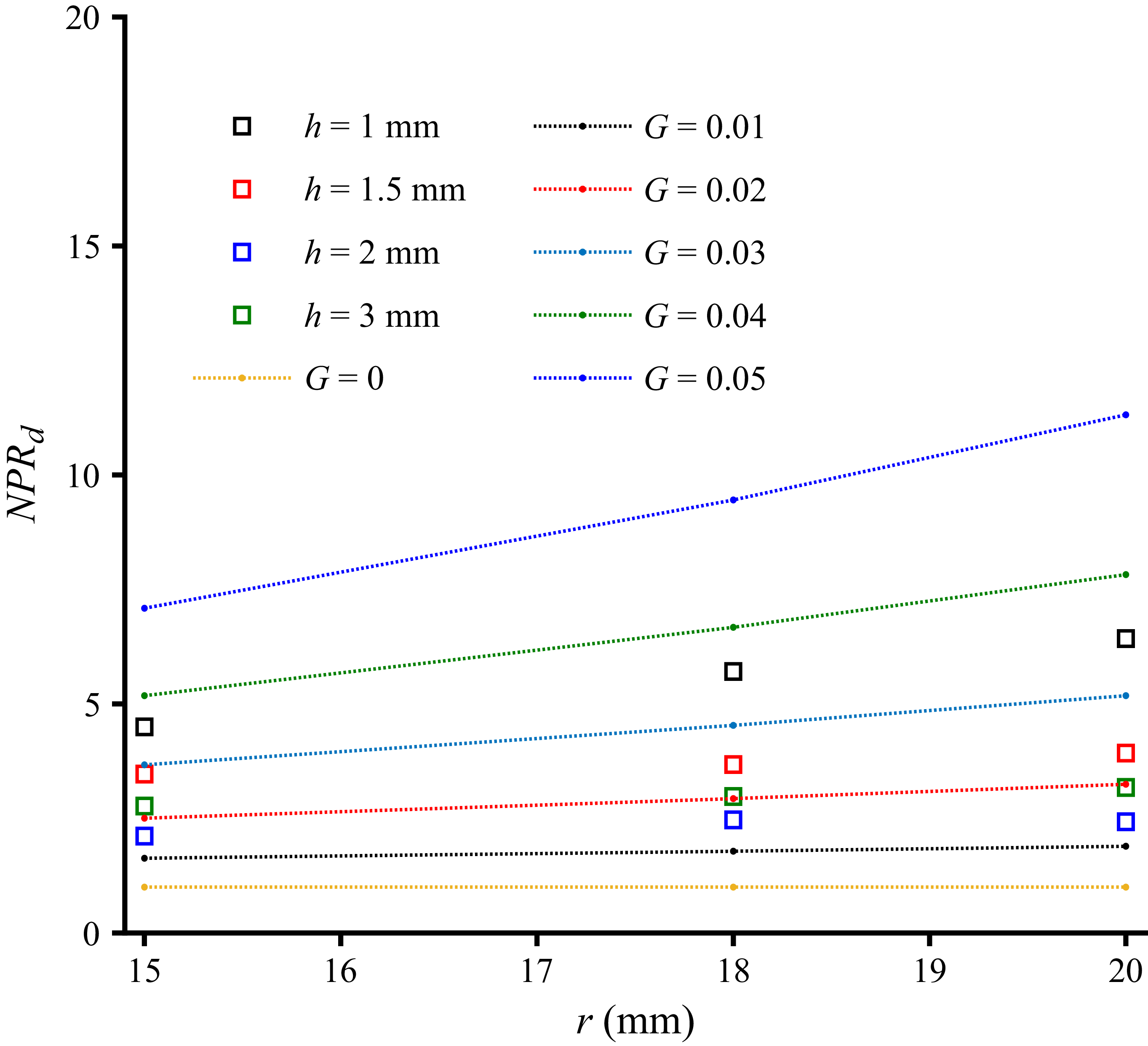
and wall radius r (s = 0 mm).

Figure 7. Long description
Panel: A line graph showing the relationship between wall radius (r in millimeters) and NPRd. The horizontal axis represents the wall radius (r) ranging from 15 to 20 millimeters. The vertical axis represents NPRd ranging from 0 to 20. The graph includes multiple data series represented by different colors and symbols. The legend indicates different step heights (h) and G values. The data series for h values are represented by squares in different colors: black for h = 1 millimeter, red for h = 1.5 millimeters, blue for h = 2 millimeters, and green for h = 3 millimeters. The data series for G values are represented by dotted lines in different colors: black for G = 0.01, red for G = 0.02, blue for G = 0.03, green for G = 0.04, and blue for G = 0.05. The yellow dotted line represents G = 0. The graph shows that as the wall radius increases, NPRd also increases for all step heights and G values. The increase is more pronounced for higher G values.
Relationship between
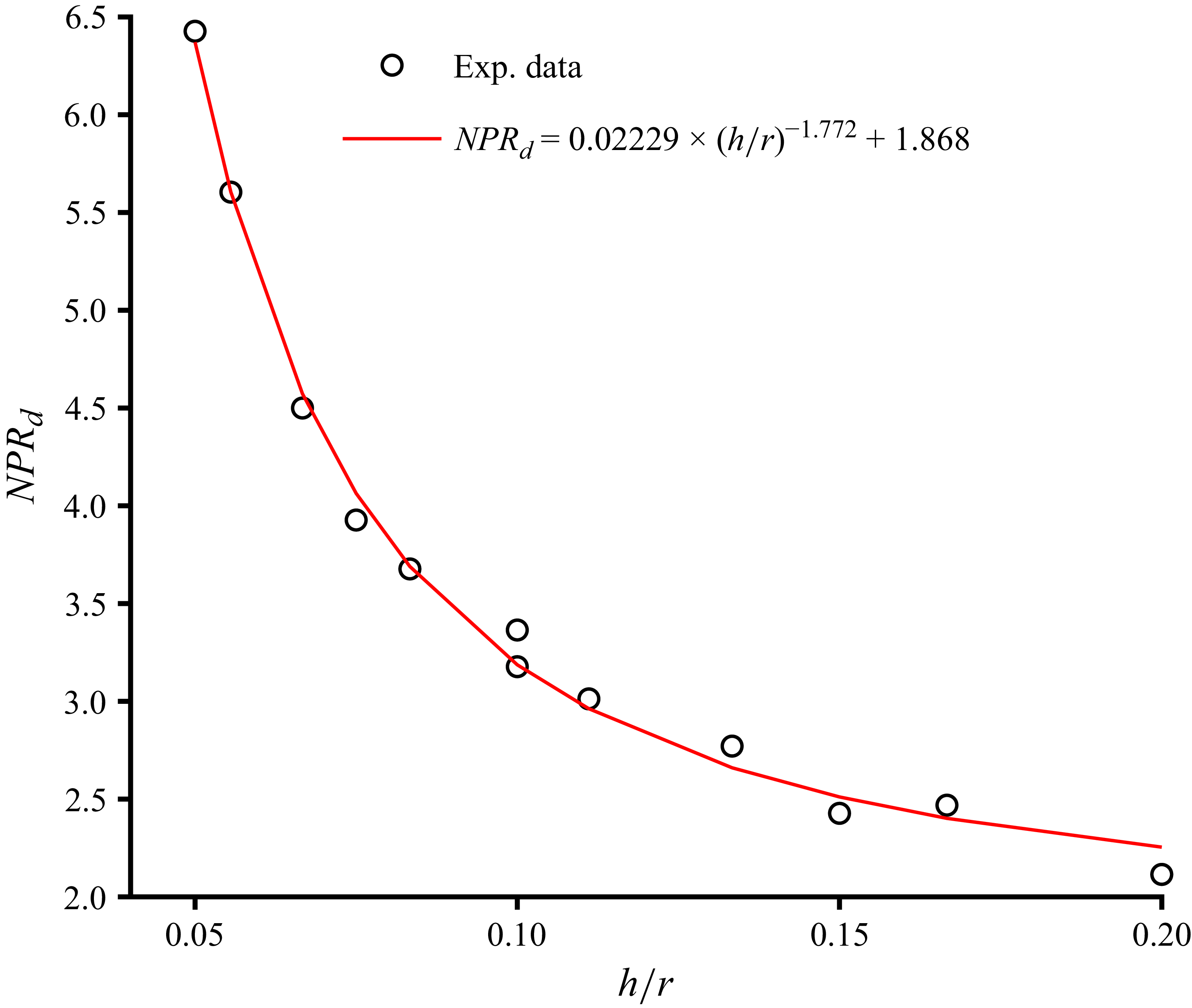
 $\textit{NPR}$
d
and h/r (s = 0 mm).

Meanwhile, (3.5) can be written as a function of r:
 \begin{equation} \textit{NPR}_{d}=\frac{P_{0}}{P_{e}}=\left(1+rG\right)^{\frac{\gamma }{\gamma -1}}\!, \end{equation}
 \begin{equation} G=\frac{\gamma -1}{2\gamma }\frac{1}{\textit{Bh}}\left(\frac{P_{e}}{P_{wall}}-1\right)\!, \end{equation}
where G is estimated between 0 and 0.14, and different values for G are used to predict
 $\textit{NPR}$
d
with s = 0 mm in figure 7. The square symbols are the experimental detachment
 $\textit{NPR}$
results, and the dotted lines refer to predicted
 $\textit{NPR}$
d
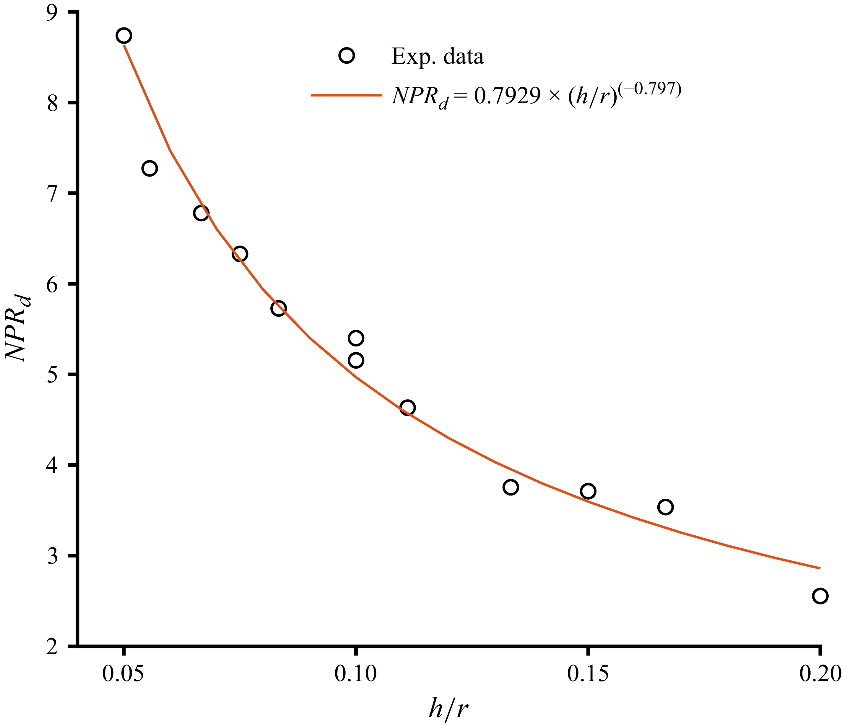
with different G values. Figure 8 illustrates the variation of
 $\textit{NPR}$
d
with h/r, alongside a power-law fit to the experimental data. Crucially, the fitted curve closely adheres to the functional form of (3.5). Collectively, the results presented in figures 6 and 8 provide compelling evidence that the detachment
 $\textit{NPR}$
of a Coanda jet over a cylindrical surface is predictable via this established scaling law. This capability is instrumental for the rational design and performance evaluation of Coanda jet generators.
3.2. ‘Step stall’ with increased step height
Figure 5 has shown that the
 $\textit{NPR}$
d
is elevated by increased step height in a specific range, which shows the same trend as mentioned in the cited articles, and the range is different for a given geometric configuration. But a new phenomenon is found in the present study: when the step height continues to increase,
 $\textit{NPR}$
d
does not increase, but instead undergoes a sudden drop at a certain step height (named the critical step height s
c
). The sudden drop phenomenon is called ‘step stall’ in the present paper, since the phenomenon is similar to the stall phenomenon of a wing model with increased angle of attack. This ‘step stall’ has not been seen in the references that we have cited so far. It reveals that an optimal step height exists for a given Coanda geometry to achieve the best performance. When s is slightly greater than the critical step height s
c
,
 $\textit{NPR}$
d
is almost equal to
 $\textit{NPR}$
d
with s = 0 mm, which means that s
c
is the step height that makes the effect of the step nonsense. When s > s
c
,
 $\textit{NPR}$
d
falls below the baseline level (s = 0 mm). This suggests that increasing the step height beyond the optimal is not beneficial but detrimental, resulting in an earlier detachment.
Figure 9 presents the flow field characteristics for a Coanda jet with wall radius of curvature r = 20 mm and slot height h = 2 mm, under four progressively increasing step heights at a representative NPRvalue. As the step height is raised, the flow structure exhibits significant simplification, characterised by a reduction in the number and complexity of shock waves and expansion waves, particularly evident in figures 9(c) and 9(d). In the near-detachment condition illustrated in figure 9(a), where
 $\textit{NPR}$
equals the detachment value (
 $\textit{NPR}$
d
), a separation bubble is observed adjacent to the wall. The growth of this bubble ultimately leads to flow separation, consistent with the mechanisms reported in prior studies (Gregory-Smith & Senior Reference He and Zhang1994). When the step height is increased to 0.3 mm (figure 9
b), the separation bubble is suppressed, and the jet remains attached to the surface. This stabilisation effect is further enhanced at a greater step height (figure 9
c), where the jet exhibits improved attachment capability, a larger stand-off distance between the shock cell structure and the Coanda wall, and the emergence of more organised, large-scale shock cells. With a further increase in step height (figure 9
d), the jet’s centreline is displaced away from the wall, increasing the effective offset distance. This configuration causes the jet to approach its critical detachment state anew, demonstrating that excessive step height can also promote the onset of flow detachment.
Examples of flow field visualisation of different step heights: (a) s = 0 mm,
 $\textit{NPR}$
= 3.18, jet is about to detach; (b) s = 0.3 mm,
 $\textit{NPR}$
= 3.18; (c) s = 1.43 mm,
 $\textit{NPR}$
= 3.18; (d) s = 1.44 mm,
 $\textit{NPR}$
= 3.15, jet is about to detach. Here, r = 20 mm, h = 2 mm.

Figure 9. Long description
Panel A: An image showing a jet outlet with no step. The jet is about to detach from the wall. Labeled parts include the expansion wave, compression wave, shear layer, separation bubble, and the end wall. Panel B: An image showing a jet with a step height of 0.3 mm. The jet is not detaching from the wall. Labeled parts include the expansion wave, compression wave, shear layer, boundary layer, step, and the end wall. Panel C: An image showing a jet with a step height of 1.43 mm. The jet is not detaching from the wall. Labeled parts include the expansion wave, shock cell, recirculation zone, step, and the end wall. Panel D: An image showing a jet with a step height of 1.44 mm. The jet is about to detach from the wall. Labeled parts include the step and the end wall.
The results from both figures 5 and 9 demonstrate the existence of an optimal step height s that maximises the detachment
 $\textit{NPR}$
. Given the displacement platform’s positioning accuracy 0.01 mm, the step height corresponding to the condition in figure 9(c) is identified as this optimal. When the feeding pressure is increased beyond this point, the jet eventually detaches from the Coanda wall, with the resulting flow structure depicted in figure 10. As shown in figure 10(a), the higher
 $\textit{NPR}$
compared to figure 9(c) results in a significantly enlarged first shock cell. Typical shock structures – specifically the reflected shock and reattachment shock – are observed; these are intrinsically linked to shock wave/boundary layer interaction, a critical phenomenon governing Coanda jet detachment (Llopis-Pascual Reference Matías-García, Bardera, Barroso and Franchini2016). However, beginning from the second shock cell, the structure dissipates relatively quickly, particularly along the upper side of the jet. A further increase in pressure leads to complete detachment, as shown in figure 10(b), where a slip line becomes visible. A key observation is that even at the elevated pressures in figures 10(a) and 10(b), the lower boundary of the first shock cell remains in close contact with the Coanda wall. This indicates a phenomenon termed ‘incomplete detachment’, which was also observed for other configurations with step heights in the range 0 ≤ s ≤ 1.43 mm.
Flow field visualisation before and after the detachment with s = 1.43 mm: (a)
 $\textit{NPR}$
= 5.05, (b)
 $\textit{NPR}$
= 5.56. Here, r = 20 mm, h = 2 mm.

When the step height exceeds 1.43 mm (for the configuration with r = 20 mm and slot height h = 2 mm), a pronounced stand-off distance emerges between the lower boundary of the first shock cell and the Coanda wall, as is evident in figure 9(d). This suggests that beyond a critical step height, the Coanda wall loses its ability to effectively entrain the jet, particularly in the region of the first shock cell. As exemplified in figure 9(d), where the step height is 1.44 mm, an increase in feeding pressure beyond 302 kPa leads to flow detachment. This occurs when the centrifugal force acting on the jet exceeds the pressure gradient that normally promotes attachment. The observed stand-off distance between the first shock cell and the wall is indicative of a weakened Coanda adhesion mechanism, likely due to the reduced effective curvature perceived by the jet. To summarise the interplay of geometric and dynamic parameters, a schematic model is presented in figure 11, illustrating the relationship between step height, wall radius, jet thickness, and the resulting detachment behaviour.
Schematic of a simplified geometric model representing the distance between the jet and the wall (r = 20 mm, h = 2 mm, s = 1.44 mm,
 $\textit{NPR}$
= 3.15, jet is about to detach).

The orange dashed line represents the Coanda wall, and it is expressed as
 \begin{equation} x^{2}+\left(y+r+s\right)^{2}=r^{2}. \end{equation}
The lower boundary of the first shock cell can be expressed as
 \begin{equation} y=ax^{2}+bx+h/2, \end{equation}
where a > 0 and b < 0 are coefficients. The distance Dis between the shock cell lower boundary and the Coanda wall is expressed as
 \begin{equation} \left| \textit{Dis}\right| =y_{\mathit{c}}-y=\sqrt{\left(a{x}_{\mathit{c}}^{2}+bx_{\mathit{c}}+h/2+r+s-\sqrt{r^{2}-x^{2}}\right)^{2}+\left(x_{\mathit{c}}-x\right)^{2}}, \end{equation}
where the subscript c represents the coordinates of the point on the lower boundary (the yellow dashed line) of the first shock cell. The minimum value of Dis can be used to represent the effective distance between the jet and the wall; however, for this type of equation, it is not possible to directly find its minimum value, and numerical solution methods can be employed. Nevertheless, (3.12) indicates that this distance is simultaneously influenced by r, h and s. The attachment of the Coanda jet occurs because the pressure gradient exceeds the centrifugal force. A greater pressure gradient can be achieved only by reducing the jet effective thickness or lowering the static pressure on the Coanda wall. Therefore, the minimum Dis might be the key element that affecting the local wall pressure. For simplicity, let x c = x. Then Dis can be expressed as
 \begin{equation} \left| \textit{Dis}\right| =ax^{2}+bx-\sqrt{r^{2}-x^{2}}+h/2+r+s. \end{equation}
According to figure 11, when s = 0, Dis should be negative; however, due to wall confinement, the lower boundary of the first shock lattice no longer satisfies (3.11), and we have
 $Dis=ax^{2}+bx+h/2+r+s-\sqrt{r^{2}-x^{2}}$
.
When
 $\textit{NPR}$
is given, the magnitude of Dis determines the intensity of the recirculation zone, and also governs the magnitude of the wall static pressure. The larger Dis, the higher the static pressure on the wall. Assuming that the wall static pressure is proportional to Dis, we have
 \begin{equation} P_{w\textit{all}}\left(x\right)=k \cdot P_{e} \cdot \textit{Dis}, \end{equation}
where k is a coefficient. When P
 ${w\textit{all}}$
(x) is large to some extent, the pressure gradient is insufficient to counteract the centrifugal force. Once the pressure ratio increases further, the jet detaches. Meanwhile, the centrifugal force is proportional to the square of the pressure, and can be simply expressed as
 \begin{equation} F_{\mathit{c}}=\frac{2\gamma }{\gamma -1}\frac{\mathit{NPR}\times P_{\mathit{e}}}{r}\big(\mathit{NPR}^{-\frac{1}{\gamma }}-\mathit{NPR}^{-1}\big), \end{equation}
 \begin{equation} \frac{\text{d}F_{\mathit{c}}}{\text{d}\mathit{NPR}}=\frac{2P_{\mathit{e}}}{r}\cdot \mathit{NPR}^{-\frac{1}{\gamma }}. \end{equation}
This means that the centrifugal force increases as
 $\textit{NPR}$
increases. In (3.14), a and b are increased with enlarged
 $\textit{NPR}$
value, and by comparing the shadowgraph results before and after jet detachment, it is found that when
 $\textit{NPR}$
changes only slightly, the shape of the first cell of the attached jet is close to that of the first cell of the detached jet. Therefore, it is considered that the influence of
 $\textit{NPR}$
on the lower boundary geometric function of the first cell of the attached jet (yellow dashed line in figures 12
a,b) follows the same trend as the influence of
 $\textit{NPR}$
on the lower boundary of the first cell of the detached jet (yellow solid line in figure 12
b).
Flow field structure before and after jet detachment: (a) jet is about to detach; (b) jet is detached. Here, r = 20 mm, h = 2 mm, s = 1.44 mm,
 $\textit{NPR}$
= 3.15.

According to the shadowgraph results, it is found that the relationship between the thickness (T c in figure 12 b) of the first shock cell and the jet outlet height is similar to the exit/throat area ratio of a supersonic nozzle under its design condition. Since the jet in this study is approximately two-dimensional, the ratio of the maximum thickness of the first shock cell to the height of the jet slot is
 \begin{equation} \frac{T_{\mathit{c}}}{h}=\left(\frac{\gamma -1}{2}\right)^{\frac{1}{2}}\left(\frac{2}{\gamma +1}\right)^{\frac{\gamma +1}{2(\gamma -1)}}\mathit{NPR}^{\frac{\gamma +1}{2\gamma }}\left(\mathit{NPR}^{\frac{\gamma -1}{\gamma }}-1\right)^{-\frac{1}{2}}, \end{equation}
 \begin{equation} \frac{{\rm d}T_{{c}}}{{\rm d}\mathit{NPR}}=\frac{h}{\gamma }\left(\frac{\gamma -1}{2}\right)^{\frac{1}{2}} \left(\frac{2}{\gamma +1}\right)^{\frac{\gamma +1}{2(\gamma -1)}}\mathit{NPR}^{-\frac{\gamma -1}{2\gamma }} \left(\mathit{NPR}^{\frac{\gamma -1}{\gamma }}-1\right)^{-\frac{3}{2}}\left(\mathit{NPR}^{\frac{\gamma -1}{\gamma }} -\frac{\gamma +1}{2}\right)\!. \end{equation}
According to the present experimental conditions and model geometry, it is known that
 ${\text{d}F_{{c}}}/{\text{d}\mathit{NPR}}\gt {\text{d}T_{{c}}}/{\text{d}\mathit{NPR}}$
, meaning that the rate of centrifugal force increase with
 $\textit{NPR}$
is greater than the rate of Dis change. Therefore, if the step is too large, then the distance between the lower boundary of the first cell and the Coanda wall cannot quickly decrease to a sufficiently small range. As
 $\textit{NPR}$
increases, the jet detaches before the lower boundary of the first cell attaches to the wall. However, if the initial step is smaller, then the distance between the lower boundary of the jet and the wall reduces to a point where the wall can effectively capture the jet, causing the static pressure on the wall to further decrease. In this case, the first shock cell of the jet can adhere closely to the wall, enhancing the jet’s ability to resist centrifugal disturbances, and thus delaying jet detachment.
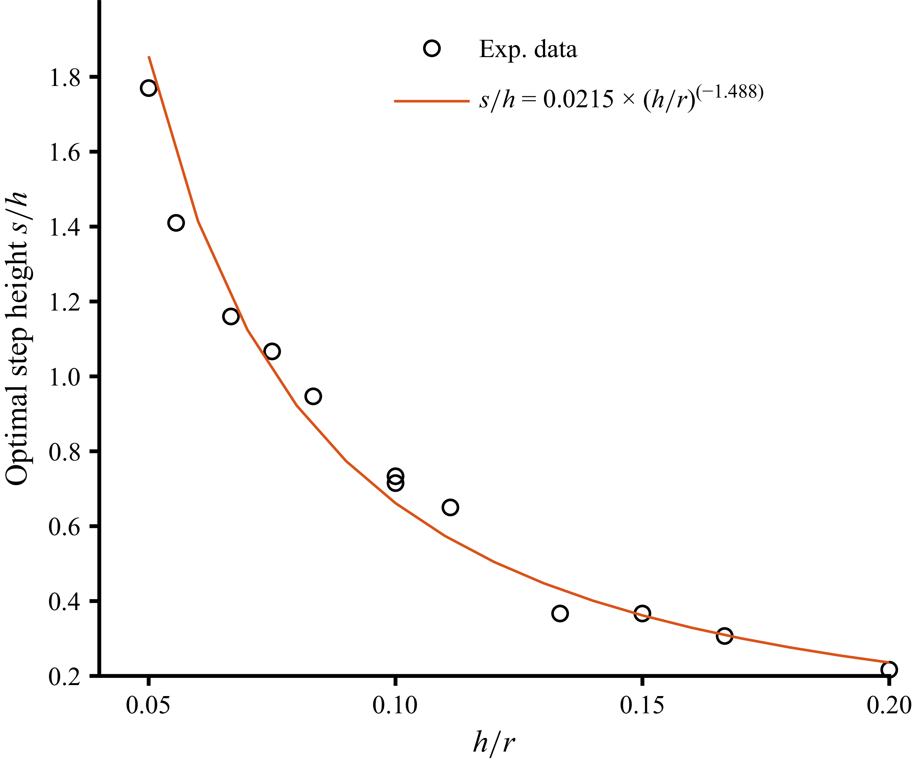
Figure 13 illustrates the relationship between the optimal step height and h/r. A power-law fit reveals that increasing or decreasing not only elevates
 $\textit{NPR}$
d
but also permits a relatively larger optimal step height at the jet outlet. Notably, the experimental data closely adhere to the functional form
 $\textit{NPR}$
d
− (r/h)
C
(where C is the exponent), which is consistent with the theoretical expression in (3.5). Furthermore, compared to the baseline case in figure 8 (s = 0), the
 $\textit{NPR}$
d
values under optimal step configurations retain this scaling law. This suggests that the introduction of a step does not disrupt the inherent power-law dependence of
 $\textit{NPR}$
d
on the geometric configuration. Physically, a larger step height facilitates fuller jet development, suppresses separation bubbles, simplifies the wave structure, and consequently enhances
 $\textit{NPR}$
d
.
Relationship between the optimal step height and h/r.

Relationship between
 $\textit{NPR}$
d
and h/r (optimal step height).

Figure 14 plots the maximum
 $\textit{NPR}$
d
against h/r. The data exhibit a power-law scaling that closely mirrors the functional form of (3.5). This consistency suggests that the introduction of a step does not fundamentally alter the underlying physical mechanism governing the relationship between the detachment pressure ratio and the geometric configuration, thereby validating the theoretical derivation.
4. Conclusions
This study presents a systematic investigation into the influence of step height on the attachment and separation characteristics of a supersonic Coanda jet. The experimental results reveal several key findings that enhance the understanding and predictive capability for Coanda effector performance.
-
(i) For the conventional Coanda configuration without a step, the detachment nozzle pressure ratio (
$\textit{NPR}$
d
) was predicted using a macroscopic mechanical model based on the balance between the centrifugal force and the radial pressure gradient. The model demonstrates a clear power-law relationship between
$\textit{NPR}$
d
and the geometric ratio h/r. Experimental data for various jet outlet heights (h) and wall radii (r) confirmed the model’s validity, providing a reliable tool for the design and evaluation of basic Coanda effectors. -
(ii) The introduction of a step at the jet outlet significantly alters the detachment characteristics. Contrary to the previously understood monotonic benefit, this study discovered a critical ‘step stall’ phenomenon. While increasing the step height (s) initially enhances attachment and raises
$\textit{NPR}$
d
by simplifying the wave structure and suppressing separation bubbles, a further increase beyond a critical value leads to a sudden, sharp drop in
$\textit{NPR}$
d
. -
(iii) The underlying mechanism is attributed to the effective distance (Dis) between the lower boundary of the first shock cell and the Coanda wall. A simplified geometric model illustrates that an excessively large step height increases this distance, preventing the wall from effectively ‘grabbing’ the jet. The centrifugal force, which increases at a faster rate with
$\textit{NPR}$
than the jet thickness, ultimately overcomes the weakened pressure gradient before the jet can reattach closely to the wall, leading to premature detachment. In contrast, a smaller or optimal step allows the jet to adhere closely to the wall, enhancing its resistance to centrifugal forces.


In summary, this work provides a comprehensive analysis of Coanda jet detachment with steps, culminating in the identification of the ‘step stall’ phenomenon. It delivers predictive models for both baseline and optimised configurations, offering critical insights for designing high-performance Coanda effectors in aerospace and other flow control applications. The relationships between geometric parameters and detachment performance established here serve as a practical guide for maximising the operational envelope of such devices.
Acknowledgements
The authors extend their sincere gratitude to the internship students from the National University of Defence Technology S. Ju and J. Shi for their invaluable assistance in completing the testing work.
Declaration of interests
The authors declare no conflict of interest.


 NPR


 NPR

 NPR
 NPR
 NPR

 NPR
 NPR
 NPR
 NPR

 NPR
 NPR

 NPR

 NPR
 NPR


