Introduction
Metamaterial is a periodic engineered structure which possesses unique electromagnetic (EM) properties which separate them from conventional materials [Reference Landy, Sajuyigbe, Mock, Smith and Padilla1]. Metamaterial has negative permittivity (ɛ) and/or negative permeability (μ) over certain range of frequency; due to this phenomenon, it supports backward waves [Reference Grbic and Eleftheriades2], negative refractive index [Reference Smith, Pendry and Wiltshire3], inverse Snell's law [Reference Xi, Chen, Jiang, Ran, Huangfu, Wu, Kong and Chen4], reverse Doppler effect [Reference Lee, Park, Seo and Kim5], etc. Considering the above unique properties, metamaterial devices are overcoming conventional devices such as cloaking [Reference Cai, Chettiar, Kildishev and Shalaev6], superlense [Reference Fang and Zhang7], resonators [Reference Bonache, Gil, Gil, García-García and Martín8], sensors [Reference Wang, Yan, Tan, Zhou and Hou9], absorbers [Reference Barde, Choubey and Sinha10], antennas [Reference Caloz and Rennings11], filters [Reference Gil, Bonache and Martin12], cross-polarizers [Reference Khan, Fraz and Tahir13], etc.
Polarization of linear EM waves by using conventional devices has a limitation of narrow bandwidth and larger volume [Reference Ranjan, Barde, Choubey, Sinha, Jain and Roy14]. To obtain wide bandwidth and compact size, metamaterial structures have been proposed. Some structures convert the linear EM waves through transmission, while others convert via reflection from the surface [Reference Kang, Woo, Choi, Lee, Kim, Kim, Hwang, Park, Kim and Wu15, Reference Chin, Lu and Cui16]. Different metamaterial structures are used for different frequency ranges such as nanorod has been used for visible region [Reference Zhao, Belkin and Alù17], split rings are used for infrared region [Reference Shi, Zhu, Ma, Jiang and Cui18], for terahertz metallic grating complementary rings are used [Reference Shi, Zhu, Ma, Jiang and Cui18, Reference Zheng, Guo and Ding19], and for microwave region diagonally placed structures are implemented [Reference Soheilifar20, Reference Bhattacharyya, Ghosh and Srivastava21].
By designing anisotropic metallic elements placed over some dielectric polarization, conversion can be obtained [Reference Ramachandran, Faruque and Ahamed22]. Different structures are designed to operate at different frequency ranges such as circular split-ring resonators (CSRR) are designed for infrared region [Reference Xu and Shi23], nanorods are designed for visible region [Reference Nama, Bhattacharyya and Chakrabarti24], self-complementary rings [Reference Chen, Wang and Ma25], double head arrows are designed for microwave region [Reference Gui, Jing, Zhou, Liu and Hong26], and metallic grating for terahertz (THz) region [Reference Ou, Lu, Xu and Lin27].
The polarization conversion bandwidth for metasurface can be enhanced by various designing techniques such as multilayer structure consists of metallic dielectric arrangements so as to produce multiple plasmonic resonance [Reference Gardezi, Pirie, Dorrell and Hoffman28], twisted CSRR but limits only for normal incidence [Reference Cohen and Shavit29], single-layer structure is designed for broad bandwidth using neighboring plasmonic resonance but not operates for oblique incidence [Reference Oraizi and Afsahi30], and another multilayer structure is reported but it is angle-dependent [Reference Liu, Li, Zhang, Huang, Li, Pei, Fang, Wang and Xiao31].
The proposed wideband metamaterial cross-polarizer (MCP) comprises of a splitted square-shaped resonating structure with two inner and one outer stub. The structure is fabricated on FR-4 substrate with an overall dimension of 8.6 mm × 8.6 mm. A wideband polarization conversion ratio (PCR) above 0.87 magnitude is achieved with a bandwidth of 3.49 GHz ranging from 8.8 to 12.29 GHz, which works for X (8–12 GHz) band approximately. Two distinct PCR peaks are observed at 9.44 and 11.47 GHz with PCR magnitude at 99.39 and 99.00% respectively. The normalized impedance and EM parameters (real and imaginary) curves proved the presence of metamaterial properties is the region of interest. The analysis of polarization conversion phenomena at two distinct frequencies is described with the help of electric field and current distribution. The structure is replicated using ANSYS HFSS 19.1 and measured inside an anechoic chamber with the help of VNA. The replicated and experimented responses obtained are almost similar to one another with adaptation due to fabrication liberality.
Structure design
The unit cell structure consists of splitted square with two inner and one outer line, placed obliquely opposite to each other as shown in Fig. 1 with EM field directions. The overall dimension of the structure is 8.6 mm × 8.6 mm (0.24λ × 0.24λ). The unit cell structure comprises of three layers. The topmost and bottommost layers are made up of copper (height = 0.035 mm) and the central layer is made up of FR-4 substrate of thickness 1.6 mm (0.04λ). The structure is replicated using ANSYS HFSS 19.1, with a periodic boundary condition (master and slave) and floquet port excitation is applied to the structure. The optimized geometrical dimensions of the unit cell are a = 8.6 mm, h 1 = 1.6 mm, h 2 = 2.6 mm, L1 = 3.4 mm, L2 = 4.2 mm.
Front view of the proposed MCP unit cell.

No transmission of EM wave occurs, because the bottom layer is completely paved with copper. This minimizes the reflection of co-polarized component of the incident EM wave from the top surface, generating cross-polarized component of the incident field, which results in maximum cross-polarization conversion (CPC). CPC refers to conversion of x polarized EM wave into resultant y polarized EM wave from FSS.
To understand the basic phenomenon behind the polarization conversion, the suggested anisotropic structure is considered as homogenous medium. The structure is symmetric about V-axis which is $45^\circ$ with reference to Y direction. On that account, viewing U, V, and Z as orthogonal system, μ UU, μ VV, μ ZZ happen to be diagonal elements on the subject of tensor $\bar{\mu }$
 .
Taking into consideration the normal incidence of y-polarized EM wave along with the decomposition of electric field vector $\overrightarrow {E_i}$ it results into two mutually independent u- and v-components, which are equal in terms of magnitude. The incidence of the electric field vector in Fig. 2 can be incorporated as [Reference Chen, Wang and Ma25].

and the reflection of the electric field vector as [Reference Chen, Wang and Ma25]

where, r U and r V define reflection coefficients of u- and v-polarized incidence of electric field vector, $\hat{U}$ and $\hat{V}$
 represent unit vectors which lie along u- and v-axis, respectively. The reflection coefficients represented as r U and r V are proven to be mutually independent because of the anisotropic behavior of the unit cell structure. Besides, the losses of dielectrics are mainly negligible owing to the minute loss tangent of dielectric substrate. This mainly results into the unit magnitude of r U and r V which gradually result into EM wave incidence for u- and v-polarization which come under no cross-polarized reflection. Supposing $\Delta \emptyset$
 to be the difference in phase between r U and r V, co-polarized along with cross-polarized reflections coefficient r YY along with r XY can be computed as demonstrated in [Reference Chen, Wang and Ma25].


Front view of the proposed MCP with x and y axes denotes the incident EM wave, whereas anisotropy is described by U and V axes.

Therefore, for $\Delta \emptyset = {\pm} 180^\circ$ , r YY = 0 while that of r XY = 1 as achieved by equations (3) and (4); furthermore, making use of this hypothesis, a conversion of 90° polarization can possibly be attained, as shown in Fig. 2.
Results and analysis
The proposed structure is simulated by commercially available Finite Element Method (FEM) solver ANSYS HFSS 19.1. The structure is applied with two types of boundary conditions master and slave in x and y directions as periodic boundary and incident EM wave in z direction. The frequency response of cross-polarized reflection and co-polarized levels is achieved as shown in Figs 3 and 4. PCR peaks are observed at 9.44 and 11.47 GHz with PCR magnitude at 99.39 and 99.00%, respectively. The reflection components for cross-polarizer sustain steady state within the band of interest. In the given context, the PCR of the structure has been eventually calculated across the frequency range from (1).

where r xx and r xy are co-polarized and cross-polarized reflection coefficients, respectively [Reference Ramachandran, Faruque and Ahamed22]. Full width half maxima (FWHM) bandwidth of PCR achieved is 4.55 GHz ranging from 8.5 to 13.05 GHz. In addition, PCR of more than 0.87 has been observed between 8.80 and 12.29 GHz over a bandwidth of 3.49 GHz. The polarization conversion band approximately covers X-band. In this band, two distinct co-polarized reflection minima combined with maximum reflection of cross-polarized components give rise to PCR maxima at 9.44 and 11.47 GHz, with PCR peaks of 99.39 and 99.00%, respectively, as shown in Fig. 5.
Simulated co-polarized reflection coefficients.

Simulated cross-polarized reflection coefficients.

Simulated PCR response.

PCR phenomenon
Consider MCP structure as a homogeneous medium, so PCR phenomenon is evaluated by the formulas given in equations (6) and (7) [Reference Chen, Wang and Ma25],


where Z is impedance, η is refractive index, K is wave number, d is thickness of MCP, and S 11 and S 21 are scattering parameters.
The bottom layer is completely covered with copper, therefore scattering parameter S 21 is zero, but to calculate normalized impedance (Z) from the above equation, S 21 is required. In order to obtain S 21, small square slots having a dimension of 0.5 × 0.5 mm2 are removed from the four corners of the bottom layer to a certain extent that the PCR responses do not deviate. Hence, S 21 is obtained as ground plane is not fully covered with copper.
Two effective parameters effective permittivity (ɛ eff) and effective permeability (μ eff) are calculated from equations (8) and (9), to explain the PCR mechanism.


The normalized input impedance Z(ω) is computed from (10) and (11),


Variation of Z(ω) versus frequency is shown in Fig. 6; it is concluded from the figure that real and imaginary parts are approaching toward unity and zero, respectively, at PCR peaks which indicated proper impedance matching is achieved resultant in maximum PCR. Z(ω) approaches toward unity because the values of ɛ eff and μ eff change rapidly at PCR frequencies.
Simulated normalized impedance.

The metamaterial behavior in the region of interest can be proved by observing Figs 7 and 8. In which real part of permittivity and permeability, similarly imaginary part of permittivity and permeability are almost similar to each other which indicates the structure is behaving as a metamaterial structure in the region of interest.
Simulated real part of permittivity and permeability.

Simulated imaginary part of permittivity and permeability.

Current and electric field distribution
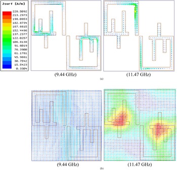
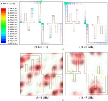
To explain minimization of co-polarized reflection coefficient, field distribution is calculated at two distinct PCR peaks (9.44 and 11.47 GHz). The current distribution at the top and bottom surface is anti-parallel with respect to each other as shown in Fig. 9. Due to circulating current, magnetic excitation is created perpendicular to magnetic field. Electric field is induced due to electric excitation as shown in Fig. 10, due to this strong EM resonance occurs which minimizes co-polarizer reflection level.
Current distribution: (a) top and (b) bottom at 9.44 and11.47 GHz of the proposed MCP.

Electric field distribution: (a) top and (b) bottom at 9.44 and11.47 GHz of the proposed MCP.

Magnetic and electric excitation occur simultaneously, proved by observing Figs 7 and 8 in which ɛ eff and μ eff get large deviation near all the two PCR peaks.
Investigation under normal and oblique incident waves
The MCP structure is investigated under normal incident wave up to 90° at each 15° increment as shown in Fig. 11. It is observed that PCR magnitude decreases as the normal incident wave moves from 0° to 45° and reaches to minimum level and again increases as the normal incident wave moves from 60° to 90° and reaches to maximum level which confirms that the proposed structure is polarization sensitive.
Simulated PCR response under normal incident wave for different polarization angles.

The structure is further examined under oblique incident wave. The proposed structure is investigated at different angles from 0° to 45° at each 15° increment for both TE and TM polarization and the PCR magnitudes are plotted in Figs 12 and 13, respectively. It is observed that PCR magnitude greater than 87% with wide bandwidth of 3.49 GHz is obtained. The response degrades as angle of incidence increases above 45°.
Simulated PCR response under oblique incident wave for TE polarization angles.

Simulated PCR response under oblique incident wave for TM polarization angles.

Measurement setup
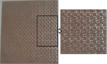
The proposed MCP is fabricated on the FR-4 substrate as shown in Fig. 14 with an array of 17 × 17 unit cell placed on the sheet, as shown in Fig. 15.
Simulated and measured co-polarization reflection coefficient.

Fabricated model of the proposed MCP with an array of 17 × 17 and an enlarged view.

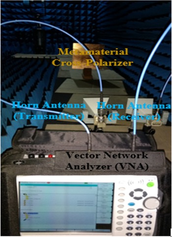
The measurement of fabricated structure is carried out inside the anechoic chamber. The fabricated sheet is placed in a stand kept at far field of two horn antennas. One antenna acts as a receiver while the other acts as a transmitter; both the antennas are connected through VNA and this full set up is positioned inside the anechoic chamber. For computing the PCR response and co-polarizer reflection coefficient on the first hand, a similar copper sheet is kept and the PCR response and co-polarizer reflection coefficient are measured, which act as a reference for other measurements. The PCR response and co-polarizer reflection coefficient of fabricated structure are computed through the medium of VNA and the difference between reference and fabrication of MCP is noted. The experimental set up inside the anechoic chamber is shown in Fig. 16.
Experimental setup inside anechoic chamber.

The combined simulated and measured curves of co-polarized and cross-polarized reflection coefficients and PCR response are shown in Figs 14, 17, and 18. A detailed comparison has been shown in Table 1 for the simulated and measured results and it is observed that these simulated and measured results are extremely closer to each other, with minute differences due to fabrication tolerance.
Simulated and measured co-polarization reflection coefficient.

Simulated and measured PCR response.

Comparison of simulated and measured results of the proposed MCP

The proposed and already reported MCP is compared with respect to size of unit cell, bandwidth, fractional bandwidth, and thickness in Table 2. It is observed from the table that the proposed MCP is compact in terms of size and thickness. The proposed MCP also has larger and fractional bandwidths compared to the reported articles and used for X-band.
Comparison of between proposed and already published MCP articles

Conclusion
A wideband MCP is proposed which consists of anisotropic design. The overall dimension of a unit cell is 8.6 mm × 8.6 mm × 1.6 mm. After simulation bandwidth of 3.49 GHz (8.8–12.29 GHz) is achieved, which approximately envelopes the X-band. The bandwidth of 4.55 GHz (8.5–13.05 GHz) at FWHM is achieved with two distinct PCR peaks at 9.44 and 11.47 GHz with PCR magnitude of 9.39 and 99.00%, respectively. The simulated and measured curves obtained for PCR response and co-polarizer reflection coefficient are similar to one another with minute difference due to fabrication tolerance. The proposed and already reported MCP are compared and it is observed that the proposed MCP is compact in terms of thickness. As the proposed MCP covers X-band, it finds practical applications in the field of civil, military, weather monitoring, air traffic control, maritime vessel traffic control, defense tracking, and vehicle speed detection for law enforcement.
 Prof. (Dr.) Neelesh Kumar Gupta, obtained Ph.D in Electronics and Communication Engineering from Rajiv Gandhi Technical University (RGTU), Bhopal (M.P.) – India. He has more than 19 years of teaching experience in reputed technical institutes. Presently, Dr. Neelesh Kumar Gupta is working as Professor & HoD of Electronics and Communication Engineering Department at Ajay Kumar Garg Engineering College, Ghaziabad (U.P.)-India. Earlier he served in TRUBA Institute of Engineering and Information Technology, Bhopal as Prof. & HoD ECE. He completed his Graduation (B.E.) in Electronics and Communication Engineering from Rajiv Gandhi Prodhyogiki Vishwavidyalaya (RGPV), Bhopal (M.P.) in 2002 and his Post-Graduation (M.Tech) from prestigious Maulana Azad National Institute of Technology (MANIT), Bhopal (M.P.) in 2007 with specialization in “Microwave and Millimetre Waves”. His area of expertise/special interest includes Signal Processing, Communication Systems and Microwave Engineering. He has published more than 30 research papers in SCI, SCOPUS Indexed, UGC approved, Peer Reviewed / reputed journals. He also has over 51 publications in reputed International/ National Conference proceedings published by IEEE Explore and Springer etc. He has successfully guided 33 M Tech scholars for Thesis / Dissertation as well guided many UG students for Projects. Also, he has one patent in the field of Signal Processing. He also Co-authored a book titled as “Fundamentals of Electronics Engineering” for Tech-Max Publications, Pune. Prof. (Dr.) Neelesh Kumar Gupta is an active member of several professional bodies / societies including IEEE, IETE, New Delhi etc. He is the reviewer and editorial member of several International Journals of repute and also chaired Technical Sessions in many International Conferences. He has organized many National Conferences, FDPs, Technical Seminars and Workshops at the institute level. His Video Lectures have been broadcasted on Swayam Prabha Channel-15 and AKTU Digital Education Portal. He was honored with reputed “Guru Faculty Award”, Best Teacher Award in Srijan-2015 and was also awarded by IETE on the occasion of Teachers Day.
 Dr. Pavan Kumar Shukla is Professor and Head of the Department of Electronics & Communication Engineering of Noida Institute of engineering and technology, Greater Noida and having more than 20 years academic experience. He has completed his doctorate in year 2017 in the field of Digital Communication, Optical Communication and Antenna. He is also working as the Technical Advisor of the Telenoetica Ltd. Lagos Nigeria, A telecommunication infrastructure provider in most of the African countries. He has published more than 20 research papers in reputed journals and guided many postgraduate projects. He is a nominated expert of the subject “antenna” by the AKTU and delivered many e-shoots for the university students. His expertise is in the field of communications and also has five patents in the field of antenna and IoT which have been published in the intellectual property of India as the chief investigator. He is a Board of Studies member for many universities, subject expert for many industries and organizations. He has chaired the many sessions of IEEE International conference and panel member for the Electronics and Communication Symposium. He has more than 20 years of academic and research experience. He has also served as Students Activity Council Chairman and Secretary of Alumni Association for more than 10 years. He has obtained multiple grants from AICTE, AKTU, DST, DRDO & from many other govt. organizations to conduct various companies, FDPs and many academic events.
 Dr. Pushpalata, obtained Ph.D in Electronics and Communication Engineering. His area of expertise/special interest includes Signal Processing, Communication Systems and Microwave Engineering. Currently she is working as Associate Professor in Department of Electronics and Communication Engineering and She is the Principal of BCE Bhagalpur.