


1. Introduction
Generated by encapsulating a liquid droplet (core) in another immiscible droplet (shell) (Heidari et al. Reference Heidari, Jafari, Ziaiifar and Malekjani2022), a compound droplet (double emulsion) has attracted painstaking attention in the wake of its numerous applications, from which one may allude to pharmaceutics (Wu et al. Reference Wu, Gao, Sun, Yang, Ye, Wang and Zhou2023a ), drug delivery (Huang et al. Reference Huang, Saadat, Bijarchi and Shafii2023), the food industry (Kumar et al. Reference Kumar, Kaur, Kumar, Kumar, Gehlot and Aggarwal2022), agriculture, lab-on-a-chip (Zhang et al. Reference Zhang, Xu, Chen and Abate2023a ) and cosmetics. Deformation and breakup are the regular phenomena a compound droplet experiences in the mentioned applications, inducing a change in their morphology and properties (Mandal et al. Reference Mandal, Ghosh and Chakraborty2016, Reference Mandal, Sinha, Bandopadhyay and Chakraborty2018; Behera, Poddar & Chakraborty Reference Behera, Poddar and Chakraborty2023). Accordingly, not only does the fundamental survey of compound droplet deformation and breakup instigate the appreciation of their underlying physics, but it also extends their applications, which is the primary stimulant for performing this research.
Deformation and breakup of the compound droplet have been investigated in extensional flow (Guilherme et al. Reference Guilherme, Siqueira, Cunha, Thompson and Oliveira2023), simple shear flow (Loewenberg & Hinch Reference Loewenberg and Hinch1996; Singeetham, Chaithanya & Thampi Reference Singeetham, Chaithanya and Thampi2021), microchannels (Santra et al. Reference Santra, Das and Chakraborty2020a
), capillary tubes (Borthakur, Biswas & Bandyopadhyay Reference Borthakur, Biswas and Bandyopadhyay2018) and other specific configurations (Vu et al. Reference Vu, Vu, Pham, Nguyen, Nguyen, Phan and Nguyen2023). Regarding extensional flow, Qu & Wang (Reference Qu and Wang2012) simulated the stability and deformation of a compound droplet in an extensional flow exploiting a three-dimensional (3-D) spectral boundary element. Exploring the impacts of the capillary number (Ca), inner droplet size, surface tension ratio and viscosity on the compound droplet stability, they asserted that a smaller core will result in a more stable compound droplet. Moreover, the initial location of the compound droplet can affect not only the droplet’s stability but also its migration velocity. Santra et al. (Reference Santra, Panigrahi, Das and Chakraborty2020b
) surveyed the concurrent influences of an electric field and extensional flow on the deformation of a compound droplet. They posited that in the extensional flow, the inner and outer droplets merely deform into the oblate and prolate shapes, respectively, while different morphologies may be observed when an electric field is brought to bear. Using an electric current model and the phase-field method, Hao et al. (Reference Hao, Li, Gao, Liu and Chen2023) simulated the deformation of an electric-field-mediated compound droplet in an extensional flow. The results imply that the compound droplet deformation may be characterised by the electrophysical parameters of the fluid, such as the conductivity ratio, extensional flow strength and electric field strength. Concerning the shear flow, examining the influences of the capillary number, radius ratio and viscosity ratio of outer to inner droplets, Chen, Liu & Shi (Reference Chen, Liu and Shi2013) numerically delved into the hydrodynamics of a compound droplet in shear flow. They observed four distinct breakup regimes and provided phase diagrams to elucidate the critical capillary number at which the breakup occurs. Luo, He & Bai (Reference Luo, He and Bai2015) numerically explored the deformation of a compound droplet in a simple shear flow via a front-tracking method. They ascertained that the deformation of the compound droplet is smaller than that of a simple droplet, which is consistent with Hua, Shin & Kim (Reference Hua, Shin and Kim2014), who numerically concentrated on the deformation dynamics of a compound droplet in a shear flow. Liu et al. (Reference Liu, Lu, Li, Yu and Sahu2021) studied deformation and breakup of a compound droplet via a three-phase lattice Boltzmann method (LBM) in an oscillatory shear flow. They expressed that the maximum deformation parameter deviates from the linearity while
 $Ca \gt 0.35$
. Furthermore, the critical Ca determining the transition from deformation to breakup is pertinent to the confinement ratio. They also alleged that raising the oscillatory period curtails the critical capillary number and alters the breakup mode. Generally speaking, although the compound droplet transport in a media encompassing constrictions has several authentic applications, including oil recovery and drug delivery (Wei et al. Reference Wei, Chen, Qiu, Zhang, Gao, Wu, Wang, Zhang and Zhu2023), the number of studies allotted to the deformation of a compound droplet in a confined geometry (e.g. tubes and microchannels) is inconsequential compared with those focused on the compound droplet deformation and breakup in the shear flow. Also, in light of the confinement effects emanating from the wall, the hydrodynamics of the compound droplets in shear and extensional flows cannot be generalised to microchannels and other microfluidic devices, necessitating further studies to illuminate their morphology in the microfluidic applications (Che, Yap & Wang Reference Che, Yap and Wang2018).
Regarding the studies that concentrate on the morphology of a compound droplet in a confined geometry, Chen et al. (Reference Chen, Li, Shum, Stone and Weitz2011) experimentally examined the breakup of a double emulsion in the orifice of a tapered nozzle by taking the effects of Ca and radius ratio into account. They constructed a phase diagram, revealing the behaviour of a compound droplet under various circumstances. Similar to the previous research, Li, Chen & Stone (Reference Li, Chen and Stone2011) explored the breakup of a double emulsion flowing through a tapered nozzle and contended that as the tilt angle of the nozzle surpasses
 $9^\circ$
, the breakup is prevented. Ho & Vu (Reference Ho and Vu2020) numerically scrutinised the deformation and breakup of a multi-core compound droplet in an axisymmetric T-junction via the front-tracking method. They reported three breakup regimes and determined the flow conditions under which the transition from non-breakup to breakup may take place. Exploiting the volume of fluid (VOF) method, Borthakur et al. (Reference Borthakur, Biswas and Bandyopadhyay2018) investigated the dynamics of a compound droplet migrating inside a capillary tube, presuming the axisymmetric condition. They concluded that the deformation of the core and shell relies on Ca; however, the influence of the capillary number on the core deformation is more conspicuous. Sattari et al. (Reference Sattari, Tasnim, Hanafizadeh and Hoorfar2021) numerically studied the deformation of a compound droplet traversing inside a microcapillary tube in non-Newtonian and Newtonian ambient fluids. They maintained that whereas linearly boosting along the tube axis in a Newtonian ambient, the centre of mass of inner and outer droplets’ position indicates a nonlinear behaviour versus time in a non-Newtonian ambient. Additionally, the properties of the ambient fluid strikingly affect the compound droplet characteristics, including average acceleration, average velocity and eccentricity. In view of its momentousness in microfluidic devices and micro-electro-mechanical systems (MEMS), the hydrodynamics of a compound droplet transporting in a microchannel merit more attention, as investigations allocated to this topic are meagre (Ma et al. Reference Ma, Zhang, Wang, Liu and Chen2023). Simulating the multiphase flow by the volume of fluid method and capturing the interface features via level set methods, Che et al. (Reference Che, Yap and Wang2018) conducted research into the flow structure within a compound droplet moving inside a microchannel. They argued that though attenuating the vortices in the shell, raising the core size accentuates the vortices in the core. In addition, the greater the capillary number, the more deformed the compound droplet becomes and the higher its eccentricity. By contrast, the viscosity ratio trivially influences the compound droplet shape. Nguyen et al. (Reference Nguyen, Vu, Vu, Truong, Ho, Pham, Nguyen and Nguyen2021) surveyed the deformation and breakup of a compound droplet travelling in a microchannel, in the middle of which a cone was included. They expressed that depending on the inertia, capillary and surface tension forces, the compound droplet may undergo deformation and breakup regimes, each of which was divided into two distinct modes. Scrutinising the hydrodynamics of a compound droplet moving in a fully developed flow under the Stokes regime, Thammanna Gurumurthy & Pushpavanam (Reference Gurumurthy Thammanna and Pushpavanam2020) posited that compared with a single droplet, the existence of the core changes the compound droplet shapes and increases its deformation. However, these studies did not use an external magnetic field to control the morphology of a compound droplet or delay its breakup during migration in a channel – a key gap addressed in this work.
Ferrofluid is a colloidal suspension constructed from nanoscale ferromagnetic particles in a base liquid (Philip Reference Philip2022), which is vastly used in different engineering facets, including microfluidics (Obeid et al. Reference Obeid, Ogah, Ogah, Ajala, Aldea, Gray, Igoli and Ferro2023), heat transfer amelioration (Benther et al. Reference Benther, Wilson, Petrini, Lappas and Rosengarten2023), drug delivery (Kole & Khandekar Reference Kole and Khandekar2021), lab-on-chip (Wu et al. Reference Wu, Gao, Sun, Yang, Ye, Wang and Zhou2023b
), and droplet manipulation (Bijarchi et al. Reference Bijarchi, Favakeh, Sedighi and Shafii2020), generation (Bijarchi et al. Reference Bijarchi, Favakeh, Alborzi and Shafii2021) and splitting (Aboutalebi et al. Reference Aboutalebi, Bijarchi, Shafii and Kazemzadeh Hannani2018). The capability to be manipulated remotely by an external magnetic field is the appealing advantage of ferrofluids, based on which numerous investigations have been fulfilled to amend their hydrodynamics and heat transfer characteristics (Shah & Khandekar Reference Shah and Khandekar2022). However, the morphology of the ferrofluid droplets under the concurrent influences of the magnetic field and hydrodynamic flows has not been unveiled yet. Concentrating on the breakup of a ferrofluid droplet in a shear flow under a uniform external magnetic field (UEMF), Hassan and Wang (Reference Hassan and Wang2019) studied the effects of viscosity ratio, magnetic field direction and strength on the breakup incidence at low Reynolds numbers. They contended that the magnetic field angles of
 $45^\circ$
and
 $90^\circ$
prompt the breakup even at low Ca, while at the angles of
 $0^\circ$
and
 $135^\circ$
, the magnetic field impedes the breakup. Using the phase-field simplified LBM, Zhang et al. (Reference Zhang, Niu, Li, Khan, Hu and Li2023b
) assessed the evolvement process of a ferrofluid droplet suspended between air and a liquid layer when the magnetic field is applied vertically. They claimed that the elongated velocity, height of the centre of mass and aspect ratio of the ferrofluid droplet are pertinent to the magnetic Bond number (
 ${Bo}_m$
). Guilherme et al. (Reference Guilherme, Siqueira, Cunha, Thompson and Oliveira2023) proposed a 3-D computational investigation to discern the effect of a UEMF on the ferrofluid droplets in planar extensional flows. They demonstrated how UEMF intensity and direction can change the rheology of ferrofluid droplets. Abdo et al. (Reference Abdo, Abicalil, Cunha and Oliveira2023) conducted numerical research into the single ferrofluid droplet subjected to the simultaneous impacts of small amplitude oscillatory shear and UEMF. Placing the ferrofluid droplet in a 3-D domain suspended in a non-magnetisable fluid, they realised how UEMF orientation and shear oscillation frequency could affect the droplet shape.
Though applying a magnetic field to manipulate a ferrofluid compound droplet (FCD) has immediate applications, notably in targeted drug delivery, investigations devoted to this paramount issue are quite elusive (Majidi et al. Reference Majidi, Bijarchi, Arani, Rahimian and Shafii2022; Huang et al. Reference Huang, Saadat, Bijarchi and Shafii2023). Huang et al. (Reference Huang, Saadat, Bijarchi and Shafii2023) investigated the formation and morphology of a double emulsion in a microfluidic system under a non-uniform magnetic field engendered by a permanent magnet. The results indicate that a lower downstream distance of the magnet from the ferrofluid junction will result in a greater core droplet aspect ratio. Majidi et al. (Reference Majidi, Bijarchi, Arani, Rahimian and Shafii2022) numerically scrutinised the deformation and breakup of a single-core FCD in a shear flow. Imposing a UEMF at various angles to acquire further control over the FCD, they assessed the influences of
 ${Ca}$
and
 ${Bo}_m$
on the compound droplet deformation when either the core or shell is ferrofluid. They appreciated that boosting the
 ${Bo}_m$
augments the elongation of inner and outer droplets along the UEMF direction. To the best of the authors’ knowledge, no scrutiny has been conducted in the literature to investigate the hydrodynamics of an FCD migrating in a fluid flow in confined geometries under the presence of a UEMF, necessitating the scholars to scrutinise the phenomenon so that the morphology and hydrodynamics of the FCD can be magnetically manipulated where required.
Based on the literature survey presented, it is essential to study the deformation and breakup of an FCD in a microchannel under the combined effects of fluid flow and a magnetic field, aiming to manipulate its morphology and delay its breakup for targeted drug delivery applications. Thus, for the first time, this study numerically surveys the hydrodynamics of an FCD migrating in a microchannel when a UEMF is imposed. The hybrid multiple-relaxation-time (MRT) lattice Boltzmann-finite difference technique is implemented to explore the multiphase flow system and the magnetic field. The influences of the
 ${Bo}_m$
,
 ${Ca}$
, density ratio, viscosity ratio, radius ratio and surface tension coefficients are examined on the morphology of the FCD when either the core or shell is ferrofluid at disparate magnetic field angles. Moreover, the regime map of the FCD breakup is established based on the non-dimensional parameters, including
 ${Bo}_m$
and
 ${Ca}$
. The research fills the gap between the fundamental subject of compound droplet hydrodynamics and site-specific drug delivery, which is an overriding challenge in bio-medical applications.
2. Numerical methodology and problem definition
In this paper, the phase-field LBM is adopted to describe the ternary fluid system, whose governing equations are elaborated on briefly in this section. Furthermore, the finite difference method (FDM) is used to discretise the magnetic field equations.
2.1. FDM for the magnetic field
The magnetic field can be procured by Maxwell’s equation for the non-conducting fluid:
 \begin{align} \nabla \boldsymbol{\cdot}\boldsymbol{{B}}=0 \end{align}
and
 \begin{align} \nabla \times \boldsymbol{{H}}=0, \end{align}
where
 $\boldsymbol{{H}}$
is the magnetic field intensity, whereas
 $\boldsymbol{{B}}$
denotes the magnetic flux density, which in turn may be attained as follows:
 \begin{align} \boldsymbol{{B}}=\mu _0(1+\chi )\boldsymbol{{H}}=\mu \boldsymbol{{H}}, \end{align}
where
 $\mu$
,
 $\mu _0$
and
 $\chi$
represent the magnetic permeability, vacuum permeability and the magnetic susceptibility, respectively. The value of
 $\mu _0$
is
 $4\pi \times 10^{-7}$
 ${N/A^2}$
. By presuming magnetisation (
 $\boldsymbol{{M}}$
) as a linear function of the magnetic field, one may have
 \begin{align} \boldsymbol{{M}}=\chi \boldsymbol{{H}}. \end{align}
In addition, owing to the curl-free constraint, the magnetic field may be expressed as
 \begin{align} \boldsymbol{{H}}=-\nabla \psi, \end{align}
where
 $\psi$
stands for the magnetic scalar potential. By incorporating (2.3) and (2.5) into (2.1), Maxwell’s equation is reduced to
 \begin{align} \nabla \cdot\left [(1+\chi )\nabla \psi \right ]=0. \end{align}
Equation (2.2) is satisfied as well. The second-order (central) isotropic FDM is exploited to obtain
 $\psi$
values across the domain. The reader is referred to the article of Kumar (Reference Kumar2004) for the detailed explanations regarding the isotropic FDM scheme. Subsequently, through (2.5), the magnetic field intensity is attained, after which the magnetic force (
 $\boldsymbol{{F_m}}$
) can be calculated:
 \begin{align} \boldsymbol{{F_m}}=-\tfrac {1}{2}\mu _0|\boldsymbol{{H}}|^2\nabla \chi. \end{align}
It is supposed that
 $\chi$
is the harmonic mean of magnetic susceptibilities of the core (
 $\chi _1$
), shell (
 $\chi _2$
) and ambient fluid (
 $\chi _3$
):
 \begin{align} \frac {1}{1+\chi }=\sum \limits _{i=1}^3 \frac {\phi _i}{1+\chi _i}, \end{align}
where
 $\phi _i$
is the phase-field variable of fluid
 $i$
. Eventually,
 $\nabla \chi$
is achieved by
 \begin{align} \nabla \chi =\sum \limits _{i=1}^3 \frac {{\textrm d}\chi _i}{{\textrm d}\phi _i}\nabla \phi _i=\frac {\sum \limits _{i=1}^3 \dfrac {\nabla \phi _i}{1+\chi _i}}{\left(\sum \limits _{i=1}^3 \dfrac {\phi _i}{1+\chi _i}\right)^2} .\end{align}
2.2. MRT-LBM for the flow field
The isothermal and incompressible multiphase flow considered in this research is governed by the continuity and Navier–Stokes equations, respectively, as follows (Zu & He Reference Zu and He2013):
 \begin{align} \nabla .\boldsymbol{{u}}=0 \end{align}
and
 \begin{align} \rho \left (\frac {\partial \boldsymbol{{u}}}{\partial t}+\boldsymbol{{u}}\boldsymbol{\cdot}\nabla \boldsymbol{{u}}\right )=-\nabla p+\nabla {\cdot}\big(\mu \big[\nabla \boldsymbol{{u}}+(\nabla \boldsymbol{{u}})^T\big]\big)+\boldsymbol{{F_s}}+\boldsymbol{{F_b}}+\boldsymbol{{F_m}}, \end{align}
where
 $\rho$
is the density,
 $\boldsymbol{{u}}$
is the macroscopic velocity and
 $p$
denotes the pressure. Also,
 $\boldsymbol{{F_s}}$
is the surface tension force, which is clarified in the paper of Liu et al. (Reference Liu, Tan, Yap, Ng and Nguyen2011). Furthermore,
 $\boldsymbol{{F_b}}=\rho g$
represents the gravitational force. Eventually,
 $\boldsymbol{{F_m}}$
stands for the magnetic force, which can be computed by (2.7).
Providing a more stable solution, notably when the viscosity and density ratio of two phases are augmented, the MRT-LBM is implemented to solve (2.10) and (2.11) (Krüger et al. Reference Krüger, Kusumaatmaja, Kuzmin, Shardt, Silva and Viggen2017; Poureslami et al. Reference Poureslami, Siavashi, Moghimi and Hosseini2021). The two-dimensional nine-velocity (D2Q9) model is exploited in this paper, whose structure is provided in figure S1 of the Supplementary Material. Herein, the MRT formulation, originally proposed by Zu and He (Reference Zu and He2013) and modified by Fakhari et al. (Reference Fakhari, Mitchell, Leonardi and Bolster2017), is used:
 \begin{align} f_{\alpha }\left (\boldsymbol{{x}}+\boldsymbol{{e_{\alpha }}}\delta t,t+\delta t\right )-f_{\alpha }(\boldsymbol{{x}},t)=-\boldsymbol{{M^{-1}}}\boldsymbol{{\Lambda }}\boldsymbol{{M}}\left (f_{\alpha }(\boldsymbol{{x}},t)-\bar {f}_{\alpha }^{eq}(\boldsymbol{{x}},t)\right )+F_{\alpha }(\boldsymbol{{x}},t), \end{align}
where
 $\delta t=1$
is the time step and
 $\boldsymbol{{e_{\alpha }}}$
denotes the particle velocity in the
 $\alpha$
-direction, while
 $\boldsymbol{{M}}$
denotes the orthogonal matrix projecting the distribution functions onto the moment space (Lallemand & Luo Reference Lallemand and Luo2000). Also,
 $\boldsymbol{{\Lambda }}$
is the diagonal relaxation matrix whose elements are selected as follows (Fakhari & Lee Reference Fakhari and Lee2013):
 \begin{align} \boldsymbol{{\Lambda }} = diag\left (1,1,1,1,1,1,1,\frac {1}{1/2+\tau },\frac {1}{1/2+\tau }\right ), \end{align}
where
 $\tau$
is the relaxation time of the flow field and can be described by (Krüger et al. Reference Krüger, Kusumaatmaja, Kuzmin, Shardt, Silva and Viggen2017)
 \begin{align} \tau =\frac {\nu }{c_s^2\delta t}, \end{align}
where
 $\nu$
is the fluid kinematic viscosity and
 $c_s$
is the lattice sound speed, whose value is
 $1/\sqrt {3}$
. It is worth mentioning that in (2.12),
 $f_{\alpha }(\boldsymbol{{x}},t)$
is the velocity-based distribution for an incompressible fluid, whose modified equilibrium may be described by (Fakhari et al. Reference Fakhari, Mitchell, Leonardi and Bolster2017)
 \begin{align} \bar {f}_{\alpha }^{eq}=f_{\alpha }^{eq}-\tfrac {1}{2}F_{\alpha }(\boldsymbol{{x}},t). \end{align}
Therefore, the equilibrium distribution is achieved by subtracting half of the forcing term from the regular equilibrium distribution function so that the collision step may be simplified. In (2.15),
 $f_{\alpha }^{eq}$
takes the following form:
 \begin{align} f_{\alpha }^{eq}=p^*\omega _{\alpha }+(\Gamma _{\alpha }-\omega _{\alpha }), \end{align}
where
 $p^*=p/\rho c_s^2$
is the normalised pressure, while the weight coefficient
 $\omega _{\alpha }$
for the D2Q9 model is given as follows (McNamara & Zanetti Reference McNamara and Zanetti1988; Chen, Martinez & Mei Reference Chen, Martinez and Mei1996):
 \begin{align} \omega _{\alpha } = \left\{\begin{array}{lc} \frac {4}{9}, & \alpha =0 ,\\[5pt] \frac {1}{9}, & \alpha =1-4, \\[5pt] \frac {1}{36}, & \alpha =5-8. \end{array} \right . \end{align}
In addition,
 $\Gamma _{\alpha }$
is the non-dimensional distribution function, which can be procured through the following relation (Abadi et al. Reference Abadi, Rahimian and Fakhari2018b
):
 \begin{align} \Gamma _{\alpha }=\omega _{\alpha }\left [1+\frac {\boldsymbol{{e_{\alpha }}}.\boldsymbol{{u}}}{c_s^2}+\frac {(\boldsymbol{{e_{\alpha }}}.\boldsymbol{{u}})^2}{2c_s^4}-\frac {(\boldsymbol{{u}}.\boldsymbol{{u}})}{c_s^2}\right ]. \end{align}
Furthermore, in (2.12),
 $F_{\alpha }(\boldsymbol{{x}},t)$
is the forcing term, which may be defined by (Zu & He Reference Zu and He2013)
 \begin{align} F_{\alpha }(\boldsymbol{{x}},t)=\delta t\omega _{\alpha }\frac {\boldsymbol{{e_{\alpha }}}\boldsymbol{\cdot}\boldsymbol{{F_{t}}}}{\rho c_s^2}, \end{align}
where
 $\boldsymbol{{F_{t}}}=\boldsymbol{{F_{\mu }}}+\boldsymbol{{F_{p}}}+\boldsymbol{{F_{s}}}+\boldsymbol{{F_{b}}}+\boldsymbol{{F_{m}}}$
represents the summation of applied forces, in which
 $\boldsymbol{{F_{\mu }}}=\nu [\nabla \boldsymbol{{u}}+(\nabla \boldsymbol{{u}})^{\textrm T}]\cdot\nabla \rho$
is the viscous force and
 $\boldsymbol{{F_{p}}}={-p}/{\rho }\nabla \rho$
is the pressure force (Fakhari et al. Reference Fakhari, Mitchell, Leonardi and Bolster2017). The implemented forcing term has been suggested and verified by Zu and He (Reference Zu and He2013). In addition, Fakhari et al. (Reference Fakhari, Mitchell, Leonardi and Bolster2017) stated that in multiphase lattice Boltzmann models, using the higher-order forms of the forcing term does not alter the results. It should be expressed that the magnetic force
 $\boldsymbol{{F_{m}}}$
is determined by FDM (see § 2.1). Moreover, in the D2Q9 model, the discrete particle velocities
 $\boldsymbol{{e_{\alpha }}}$
are (McNamara & Zanetti Reference McNamara and Zanetti1988; Chen et al. Reference Chen, Martinez and Mei1996)
 \begin{align} \boldsymbol{{e_{\alpha }}} = \left \{ \begin{array} {lc} (0,0), & \alpha =0, \\[5pt] ({\cos}[(i-1)\pi /2],{\sin}[(i-1)\pi /2])c, & \alpha =1{-}4, \\[5pt] ({\cos}[(2i-9)\pi /4],{\sin}[(2i-9)\pi /4])\sqrt {2}c, & \alpha =5{-}8, \end{array} \right . \end{align}
where
 $c=\delta x/\delta t$
is the lattice speed, while
 $\delta x$
is the steaming length.
Ultimately, once (2.12) is solved, the pressure and velocity fields can be accomplished respectively as follows:
 \begin{align}&\quad p=\rho c_s^2\sum \limits _{\alpha }f_{\alpha }, \end{align}
 \begin{align}& \boldsymbol{{u}}=\sum \limits _{\alpha }f_{\alpha }\boldsymbol{{e_{\alpha }}}+\frac {\boldsymbol{{F_t}}}{2\rho }\delta t. \end{align}
It is worth mentioning that the distribution function
 $f_{\alpha }$
is dimensionless. Furthermore, for the sake of simplicity, we take
 $\delta x=1$
and
 $\delta t=1$
in all simulations.
2.3. A conservative phase-field model for the interface
In the phase-field model, in lieu of abrupt changes across the interface of various fluids involved, the thermophysical properties of the fluid are gradually altered in the transition region (Abadi et al. Reference Abadi, Rahimian and Fakhari2018b ). Two phase-field theories have been introduced, namely Cahn–Hilliard (C–H) (Bracco et al. Reference Bracco, Giannelli, Reali, Torre and Vázquez2023) and Allen–Cahn (A–C) models (Wang, Xia & Li Reference Wang, Xia and Li2023). The selection between the A–C and C–H models should be based on the specific phenomena being considered, as discussed by Li et al. (Reference Li, Jeong, Kim, Lee and Kim2019). In this research, we adopt the conservative A–C model suggested by Sun and Beckermann (Reference Sun and Beckermann2007) and amended by Chiu & Lin (Reference Chiu and Lin2011), which is delineated as follows (Abadi et al. Reference Abadi, Rahimian and Fakhari2018b ):
 \begin{align} \frac {\partial \phi _i}{\partial t}+\nabla .(\boldsymbol{{u}}\phi _i)=M_i\nabla .\left [\nabla \phi _i-\boldsymbol{{n_i}}\frac {4}{\xi }\phi _i(1-\phi _i)+\frac {1}{3}\sum \limits _{i=1}^3\boldsymbol{{n_i}}\frac {4}{\xi }\phi _i(1-\phi _i)\right ], \end{align}
where
 $M_i$
indicates the mobility of fluid
 $i$
. Also, the interface width is symbolised by
 $\xi$
. Presumed to be the same for all phases,
 $\xi = 5$
lattice units is adopted for all simulations (Boyer & Lapuerta Reference Boyer and Lapuerta2006). Furthermore,
 $\boldsymbol{{n_i}}= {(\nabla \phi _i)}/{(|\nabla \phi _i|)}$
denotes the unit vector normal to the interface of fluid
 $i$
. The ternary system governed by (2.23) should comply with two paramount constraints for which the reader is referred to the article of Abadi et al. (Reference Abadi, Rahimian and Fakhari2018b
).
It is worth mentioning that the phase-field variables satisfy the following relation:
 \begin{align} \phi _1+\phi _2+\phi _3=1, \end{align}
which conveys that due to the conservation of mass, merely two of the phase-field variables should be computed, while the third one is attained through (2.24).
Also, the chemical potential (
 $\mu _{\phi _i}$
) of each phase may be procured by (Abadi et al. Reference Abadi, Fakhari and Rahimian2018a
)
 \begin{align} \mu _{\phi _i}=\frac {4\gamma _T}{\xi }\sum \limits _{j\neq i} \left [\frac {1}{\gamma _j}\left (\frac {\partial {\mathscr{H}}}{\partial \phi _i}-\frac {\partial {\mathscr{H}}}{\partial \phi _j}\right )\right ]-\frac {3}{4}\xi \gamma _t\nabla ^2\phi _i, \end{align}
where
 $\gamma _T$
can be achieved by the following relation:
 \begin{align} \frac {3}{\gamma _T}=\frac {1}{\gamma _1}+\frac {1}{\gamma _2}+\frac {1}{\gamma _3}, \end{align}
where
 $\gamma _i$
is an auxiliary coefficient, whose definition is provided as
 \begin{align} \gamma _i=\sigma _{ij}+\sigma _{ik}-\sigma _{jk}, \qquad i,j,k=1,2\, {\textrm and}\, 3, \end{align}
where
 $\sigma _{ij}$
represents the surface tension between phases
 $i$
and
 $j$
.
Moreover, in (2.25),
 $\mathscr{H}$
denotes the bulk free energy, which is described as follows (Boyer et al. Reference Boyer, Lapuerta, Minjeaud, Piar and Quintard2010):
 \begin{align} \mathscr{H}(\phi _1, \phi _2, \phi _3)&= \sigma _{12}\phi _1^2\phi _2^2+\sigma _{13}\phi _1^2\phi _3^2+\sigma _{23}\phi _2^2\phi _3^2+\phi _1\phi _2\phi _3(\gamma _1\phi _1+\gamma _2\phi _2+\gamma _3\phi _3) \nonumber\\ &\quad +\eta \phi _1^2\phi _2^2\phi _3^2 ,\end{align}
where the constant parameter
 $\eta$
is zero for partial spreading, while it is non-zero for total spreading. Through the spreading parameter
 $S_i=-\gamma _i$
, one may differentiate between partial and total spreading. Indeed, when
 $S_i\gt 0$
for at least one phase, the total spreading condition is acquired. In contrast, as
 $S_i\lt 0$
for all phases, the partial spreading case is achieved (Boyer & Lapuerta Reference Boyer and Lapuerta2006).
2.4. LBM for the interface tracking
An additional distribution function is employed so that (2.23) can be solved by the LBM (Abadi et al. Reference Abadi, Rahimian and Fakhari2018b ):
 \begin{align} g_{\alpha }^i(\boldsymbol{{x}}+\boldsymbol{{e_{\alpha }}}\delta t,t+\delta t)= g_{\alpha }^i(\boldsymbol{{x}},t)-\frac {g_{\alpha }^i(\boldsymbol{{x}},t)-g_{\alpha }^{i,eq}(\boldsymbol{{x}},t)}{\tfrac {1}{2}+\tau _{\phi }}+F_{\alpha }^{\phi ,i}(\boldsymbol{{x}},t), \end{align}
where
 $g_{\alpha }^i$
and
 $g_{\alpha }^{i,eq}$
are the phase-field distribution function and phase-field equilibrium distribution function of fluid i, respectively. Also,
 $\tau _{\phi }$
is the phase-field relaxation time, which can be determined as follows (Fakhari et al. Reference Fakhari, Mitchell, Leonardi and Bolster2017):
 \begin{align} \tau _{\phi } =\frac {M}{c_s^2\delta t}, \end{align}
where the mobility
 $M$
is presumed to be constant for all fluids (
 $M = 0.1$
). The sensitivity of the results to the mobility is analysed in the Supplementary Material, which demonstrates that for the configuration and parameter range studied, variations in
 $M$
results in trivial differences in key physical quantities. In addition,
 $F_{\alpha }^{\phi ,i}(\boldsymbol{{x}},t)$
is the representative of the source term whose definition is provided by Majidi et al. (Reference Majidi, Bijarchi, Arani, Rahimian and Shafii2022). Moreover, the phase-field equilibrium distribution function of the fluid
 $i(g_{\alpha }^{i,eq})$
may be obtained as follows (Abadi et al. Reference Abadi, Rahimian and Fakhari2018b
):
 \begin{align} g_{\alpha }^{i,eq}=\phi \Gamma _{\alpha }-\tfrac {1}{2}F_{\alpha }^{\phi ,i}, \end{align}
where
 $\Gamma _{\alpha }$
was introduced earlier. When (2.29) is solved via the conventional collision and streaming procedure, the phase-field variable can be attained by
 \begin{align} \phi _i= \sum \limits _{\alpha }g_{\alpha }^i \quad i=1,2. \end{align}
Also, based on (2.24),
 $\phi _3=1-\phi _1-\phi _2$
(Abadi et al. Reference Abadi, Rahimian and Fakhari2018b
). Afterwards, density can be calculated by linear interpolation:
 \begin{align} \rho = \sum \limits _{i=1}^3\rho _i\phi _i .\end{align}
Subsequently, the gradient and Laplacian of the phase-field variables may be respectively attained through the following equations:
 \begin{align}&\qquad\quad \nabla \phi _i= \frac {c}{c_s^2\delta x}\sum \limits _{\alpha }\boldsymbol{{e_{\alpha }}}\omega _{\alpha }\phi _i(\boldsymbol{{x}}+\boldsymbol{{e_{\alpha }}}\delta t,t), \end{align}
 \begin{align}& \nabla ^2\phi _i= \frac {2c^2}{c_s^2(\delta x)^2}\sum \limits _{\alpha }\omega _{\alpha }[\phi _i(\boldsymbol{{x}}+\boldsymbol{{e_{\alpha }}}\delta t,t)-\phi _i(\boldsymbol{{x}},t)] .\end{align}
The unit vector normal to the interface (
 $\boldsymbol{{n_i}}={(\nabla \phi _i)}/{(|\nabla \phi _i|)}$
) can be determined by the gradient of the phase-field variable (2.34). Ultimately, in the MRT-LBM formulation, the surface tension force takes the following form (Abadi et al. Reference Abadi, Fakhari and Rahimian2018a
):
 \begin{align} \boldsymbol{{F_s}}=\sum \limits _{i=1}^3\mu _{\phi _i}\nabla \phi _i. \end{align}
The algorithm through which the hybrid LBM-FDM approach is executed for characterising the ternary flow system and the magnetic field is demonstrated in figure 1.
The used numerical algorithm to fulfil hybrid LBM-FDM simulations.

2.5. Problem definition
Figure 2 reveals the configuration of a single-core FCD in a horizontal microchannel under the simultaneous impacts of the pressure-driven flow and a UEMF. The UEMF, which is imposed at the angle
 $\alpha$
relative to the horizontal axis, has a constant strength of
 $H_0$
. The inner and outer droplets bear the radius of
 $r_1$
and
 $r_2$
, respectively. The investigation is conducted in two scenarios, in the first of which, the inner droplet is supposed to be ferrofluid, whereas in the second scenario, the outer droplet is ferrofluid. In each scenario, the influence of the magnetic field on the deformation and breakup of the compound droplet is punctiliously surveyed. At the inception of the computation, the compound droplet, whose core and shell are spherical and concentric, is located at the distance of
 $4r_1$
from the channel inlet. Moreover, the compound droplet centre is coincident with the channel centreline. The microchannel length and height are
 $L$
and
 $H$
, respectively. All fluids are presumed to be Newtonian, incompressible and immiscible. Throughout the text, the subscripts 1, 2 and 3 refer to the inner droplet (core), outer droplet (shell) and ambient fluid, respectively.
Schematic of the initial configuration of the FCD moving in a microchannel.

The bounce-back boundary condition is applied to the top and bottom walls so that the no-slip boundary may be achieved (Krüger et al. Reference Krüger, Kusumaatmaja, Kuzmin, Shardt, Silva and Viggen2017). In addition, the inlet velocity condition with a fully developed laminar flow is brought to bear on the left side according to the Zou & He (Reference Zou and He1997) model as follows:
 \begin{align} \left \{ \begin{array} {l} u = 4u_{avg}\dfrac {y}{H}\left (1-\dfrac {y}{H}\right ), \\[6pt] v = 0, \end{array} \right . \end{align}
where
 $u_{avg}$
is the average inlet velocity. Furthermore, having a promising accuracy in binary (Mitchell et al. Reference Mitchell, Majidi, Rahimian and Leonardi2021) and ternary (Wang et al. Reference Wang, Semprebon, Liu, Zhang and Kusumaatmaja2020) fluids, the convective boundary condition (CBC) is imposed on the right side as the outlet boundary condition.
Herein, the outer droplet diameter is considered as the characteristic length; thus, the dimensionless time can be defined as
 \begin{align} t^*=\frac {tu_{avg}}{2r_2}, \end{align}
in which
 $t$
is the physical time. The dimensionless parameters via which the dynamics of the problem may be delineated are provided as
 \begin{align} r_r=\frac {r_2}{r_1},\quad \rho _r=\frac {\rho _1}{\rho _2}=\frac {\rho _3}{\rho _2}, \quad \nu _r=\frac {\nu _1}{\nu _2}=\frac {\nu _3}{\nu _2}, \end{align}
where
 $r_r$
,
 $\rho _r$
and
 $\nu _r$
are the ratios of radius, density and kinematic viscosity, respectively. Furthermore, specifying the ratio of viscous force to the interfacial tension force,
 ${Ca}$
can be determined by
 \begin{align} {Ca}=\frac {\rho _3\nu _3u_{avg}}{\sigma _{23}}, \end{align}
where
 $\sigma _{23}$
symbolises the surface tension between the shell and ambient fluid. Moreover, representing the ratio of the magnetic force to the interfacial tension force,
 ${Bo}_m$
may be described as follows depending on which droplets (core or shell) are treated as ferrofluid:
 \begin{align} {Bo}_m = \left \{\begin{array}{@{\!}lc} \dfrac {\mu _0\chi _1H_0^2r_1}{2\sigma _{12}}, & {\textrm{inner}\quad \textrm{droplet}\quad \textrm{is}\quad \textrm{ferrofluid}}, \\[10pt] \dfrac {\mu _0\chi _2H_0^2\big(r_2^2-r_1^2\big)}{2(\sigma _{12}r_1+\sigma _{23}r_2)}, & {\textrm{outer}\quad \textrm{droplet}\quad \textrm{is}\quad \textrm{ferrofluid}}, \end{array} \right. \end{align}
where
 $\chi _1$
and
 $\chi _2$
are set to unity whenever the inner and outer droplets are ferrofluid, respectively; otherwise, they are fixed at zero. Additionally,
 $\chi _3=0$
in all simulations. Also,
 $\sigma _{12}$
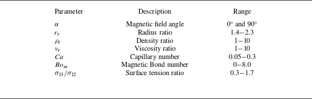
indicates the surface tension between the inner and outer droplets. Table 1 summarises the ranges at which the mentioned parameters vary in this research.
Variations of parameters exploited in this research.

To evaluate the FCD deformation prior to the rupture quantitatively, the following relation is used (Vu et al. Reference Vu, Vu, Nguyen and Pham2019b ):
 \begin{align} T_{o}=\frac {\unicode{x1D4C1}_{y_{o}}-\unicode{x1D4C1}_{x_{o}}}{\unicode{x1D4C1}_{y_{o}}+\unicode{x1D4C1}_{x_{o}}}, \end{align}
where
 $T_{o}$
is the deformation index of the outer droplet,
 $\unicode{x1D4C1}_{y_{o}}$
is the maximum distance between the upper and lower points of the outer droplet interface, whereas
 $\unicode{x1D4C1}_{x_{o}}$
indicates the maximum distance between the left and right front of the outer droplet interface, located in channel centreline. Here,
 $T_i$
,
 $l_{y_i}$
and
 $l_{x_i}$
are defined similary for the inner droplet. Given (2.39), when
 $T_o\lt 0$
, the shell stretches in the
 $x$
direction, resulting in an oblate-like shape. In contrast, for
 $T_o\gt 0$
, the shell elongates in the
 $y$
direction, giving rise to a prolate-like configuration, which is also the case for the inner droplet. Herein, the breakup is defined as the condition under which the inner droplet touches the interface of the shell. Figure 3 displays the non-dimensional numbers associated with the deformation and breakup phenomena, in which
 $t_b^*$
is the non-dimensional time at which the breakup occurs. Here,
 $y_b^*$
is a dimensionless parameter quantifying the distance between the channel centreline and the breakup point. Additionally, non-dimensionalised by the channel height,
 $L_b^*$
represents the breakup location with respect to the
 $y$
-axis
 $(x = 0)$
. In this research, the terms rupture and breakup are employed interchangebly.
Definition of the non-dimensional numbers associated with the FCD deformation and breakup.

The present study investigates three simultaneous physical phenomena: (1) the interaction between the existing phases and the resulting morphology; (2) the elongation of a droplet under a uniform magnetic field; and (3) the migration of a droplet under a fully developed pressure-driven flow. The first two phenomena were independently validated in our previous study (Majidi et al. Reference Majidi, Bijarchi, Arani, Rahimian and Shafii2022) using widely adopted benchmark cases. However, in contrast to our previous work (Majidi et al. Reference Majidi, Bijarchi, Arani, Rahimian and Shafii2022), we have modified the inlet and outlet boundary conditions to simulate droplet migration through a microchannel under pressure-driven flow. To validate these newly implemented boundary conditions, we compared our results with those reported by Wang et al. (Reference Wang, Semprebon, Liu, Zhang and Kusumaatmaja2020), demonstrating an excellent agreement. Details of this validation case are provided in the Supplementary Material.
2.6. Grid convergence
As alluded to previously, the domain size is
 $L\times H$
, in which the channel length (
 $L$
) is six times as high as the channel height (
 $H$
). Additionally, compared with the shell diameter,
 $L$
is chosen to be sufficiently long to ensure that the channel outlet does not influence the droplet migration or rupture processes. To ensure grid independence, three grid resolutions of
 $100 \times 600, 150 \times 900$
and
 $200 \times 1200$
are explored. Figure 4 compares the grid refinement results when the shell is ferrofluid,
 ${Ca} = 0.15$
,
 $\alpha =0^\circ$
and
 $r_r=1.75$
, while the other ratios are fixed at 1. The convergence results encompass the variations of the outer droplet deformation (
 $T_o$
) with respect to the magnetic Bond number (figure 4
a) when
 $t^*=1.84$
, the compound droplet shape at
 ${Bo}_m = 2$
(figure 4
b) when
 $t^*=1.84$
and the migration process of the FCD at distinct moments for different grids (figure 4
c). The difference between the two finer grids (
 $150 \times 900$
and
 $200 \times 1200$
) is, on average, 5.2 %. Conversely, the results yielded from the coarse grid (
 $100 \times 600$
) significantly deviate from the finest one with an average error of 17.8 %. Therefore, from now on, the grid size of
 $150 \times 900$
is used for the simulations, which reduces the computational time compared with the finest grid, although not influencing the accuracy of the results. The grid convergence is also explored for distinct values of the
 ${Ca}$
and
 ${Bo}_m$
, corresponding to the distinguished regimes observed during the transport of an FCD in the microchannel under the UEMF (see § 3.7), whose results are given in figure S2 of the Supplementary material.
Comparison of the results procured by distinct grid resolutions to ascertain the foremost grid size for the rest of the simulations: (a) the variations of the outer droplet deformation (
 $T_o$
) with the magnetic Bond number; (b) compound droplet shape when transporting in the channel at
 ${Bo}_m = 2$
; and (c) the migration process of an FCD in the microchannel at various moments. The results are presented at
 $t^* = 1.84$
when
 ${Ca} = 0.15$
,
 $\alpha =0^\circ$
,
 $r_r=1.75$
,
 $\rho _r=1$
,
 $\nu _r=1$
and the shell is treated as ferrofluid.

3. Results and discussion
In this section, the impacts of the influential parameters on the deformation and breakup of an FCD moving in a microchannel under the concurrent existence of the background pressure-driven flow and the magnetic field are assessed systematically. Initially, § 3.1 is dedicated to scrutinising the influence of the magnetic Bond number on the FCD deformation dynamics depending on whether the core or shell is ferrofluid for two different magnetic field angles of
 $0^\circ$
and
 $90^\circ$
. Afterwards, the effects of capillary number, density ratio, viscosity ratio, radius ratio and surface tension coefficients are investigated in §§ 3.2 to 3.6, respectively. Ultimately, § 3.7 is allocated to analysing the compound droplet morphology and distinguished regimes occurring at the rupture moment. Unless otherwise stated, simulations are fulfilled for
 ${Ca}=0.15$
,
 $\rho _r=1$
,
 $\nu _r=1$
,
 $r_r=1.75$
and
 $\sigma _{12}=\sigma _{23}=\sigma _{13}$
. In addition, the radius of inner and outer droplets are fixed at 20 and 35 lattice units, respectively. It should be noted that the microchannel confinement ratio,
 $\lambda =({2r_2})/{H}$
, is maintained at a constant value (
 $\lambda =0.47$
) throughout the manuscript. The effect of this parameter on FCD deformation is discussed separately in the Supplementary material. Furthermore, as a case study, the hydrodynamics of two conventional configurations of compound droplets, namely oil-in-water-in-oil (O/W/O) and water-in-oil-in-water (W/O/W), are also investigated, whose results are provided in the Supplementary material. The paramount purpose of the following results is to alter the governing parameters such that the rupture is postponed, which is indispensable in the targeted drug delivery application.
3.1. Impact of the magnetic Bond number
3.1.1. The core is ferrofluid
Figures 5(a) and 5(b) reveal the temporal evolution of the inner and outer droplets’ deformation, respectively, for various
 ${Bo}_m$
in advance of the rupture, in which the inner droplet is assumed to be ferrofluid (
 $\chi _1=1$
) and
 $\alpha =0^\circ$
. Also, figure 5(c) indicates the variations of
 $t_b^*$
,
 $L_b^*$
and
 $y_b^*$
with respect to
 ${Bo}_m$
. Figure 6 compares the configuration of the FCDs when transporting in the microchannel, where the solid red and solid green lines are indicative of the interface of inner and outer droplets, respectively. In fact, in the represented contours, the interface is indicated at
 $\phi _i=0.5$
. It should be expressed that the compound droplet shape after the breakup is also encompassed in the represented contours so that readers may gain a more exhaustive insight into its morphology.
Influence of
 ${Bo}_m$
on the FCD deformation and breakup over the course of traversing in a microchannel: (a) variation of the shell deformation with respect to the dimensionless time; (b) variation of the inner droplet deformation with dimensionless time; and (c)
 $L_b^*$
,
 $t_b^*$
and
 $y_b^*$
as a function of the magnetic Bond number. The inner droplet is supposed to be ferrofluid and
 $\alpha =0^\circ$
.

Migration of an FCD inside a microchannel from the initial point to the outlet over time for various magnetic Bond numbers at
 $\alpha =0^\circ$
when the inner droplet is ferrofluid. From left to right:
 $t^* = 0, \ 1.22, \ 2.45, \ 3.67, \ 4.9, \ 6.12$
and
 $\ 7.35$
.

Regarding figures 5(a) and 5(b), at
 ${Bo}_m = 0$
in which the magnetic field is not imposed, the compound droplet migrates under the sole effect of the background pressure-driven flow. This flow induces a drag force, which elongates the outer and inner droplets along the
 $x$
and
 $y$
axes, leading to negative and positive deformation parameter values, respectively, as shown in figure 6. To put it another way, the outer droplet stretches along the flow direction, engendering an oblate-like shape, while the inner droplet deforms perpendicular to the flow, provoking a prolate-like shape, which is consistent with the results provided by Santra, Das & Chakraborty (Reference Santra, Das and Chakraborty2019). Since experiencing a lower drag force owing to its smaller size, the inner droplet moves more swiftly than the shell, implying that the compound droplet deforms eccentrically during traversing in the microchannel, resulting in the breakup phenomenon at
 $t_b^*=5.71$
. Additionally, when
 ${Bo}_m = 0$
, the deformation of the inner droplet is, on average, 57.0 % greater than that of the outer droplet, arguably emanating from the difference in the drag force applied to them.
Based on figures 5 and 6, once applied, the external magnetic field drastically alters the deformation of the FCD, conveying that by deploying the magnetic field, one may cause or hinder the changes in the FCD morphology during its movement in a pressure-driven flow. It is worth mentioning that when the inner droplet is assumed to be ferrofluid, the magnetic force is imposed solely on the interface of the inner droplet, whose diagram is illustrated and discussed later in this section. In other words, the magnetic force is not applied to the outer droplet interface since it is merely imposed on the interfaces where
 $\nabla \chi \neq 0$
(see (2.7)). In the case of the outer droplet, the drag force elongates the shell in the
 $x$
direction and deforms its rear side to a flat shape (see figure 6). Interestingly, although the magnetic force is not brought to bear on the shell interface,
 $T_o$
rises with the
 ${Bo}_m$
increment, as evident in figure 5(a). In fact, the magnetic force stretches the inner droplet horizontally, compressing the fluid in the frontal side of the shell, which exerts an outward force on the shell interface, leading to its further horizontal elongation in the frontal side. Given the inner droplet, the drag and magnetic forces compete to elongate the core along and perpendicular to the flow direction, respectively, justifying why
 $T_i$
is not raised monotonously with time and minimum points are observed for the
 $T_i$
diagrams in figure 5(b). Indeed, at the inception of the migration, the magnetic force brings about an oblate-like shape; however, the viscous force gradually reduces the deformation magnitude, axiomatic in figure 5(b). When
 ${Bo}_m \lt 4$
, the viscous force eventually surpasses the magnetic force, deforming the inner droplet into the prolate-like shape
 $(T_i\gt 0)$
at the rupture moment. Conversely, at
 $ {Bo}_m \geqslant 4$
, the magnetic force prevails over the viscous force; hence, the inner droplet preserves its oblate-like configuration (
 $T_i\lt 0$
). By augmenting the magnetic Bond number, inasmuch as chosen to be ferrofluid, the inner droplet undergoes much more deformation than the outer droplet, as vivid in figure 5.
Figure 5(c) suggests that increasing the magnetic Bond number slightly reduces
 $t_b^*$
and
 $L_b^*$
. Actually, by strengthening the magnetic field, since ferrofluid, the inner droplet stretches drastically while the outer droplet is less elongated along the
 $x$
-axis, gradually diminishing the distance between the core and shell, which gives rise to the rupture phenomenon. Accordingly, a higher
 ${Bo}_m$
number will result in a sooner breakup and shorter breakup length (
 $L_b^*$
), from which one may infer that selecting the inner droplet as the ferrofluid and applying the magnetic field at
 $\alpha =0^\circ$
would be unfavourable for postponing the rupture process. Furthermore, concerning figure 5(c),
 $y_b^*$
declines with the magnetic Bond number since by intensifying the magnetic field, the frontal side of the outer droplet becomes narrow and prolonged, lowering the height at which the inner droplet contacts the shell at the rupture instant.
Influence of
 ${Bo}_m$
on the FCD deformation and breakup over the course of traversing in a microchannel: (a) variation of the shell deformation with respect to the dimensionless time; (b) variation of the inner droplet deformation with dimensionless time; and (c)
 $L_b^*$
,
 $t_b^*$
and
 $y_b^*$
as a function of the magnetic Bond number. The inner droplet is supposed to be ferrofluid and
 $\alpha =90^\circ$
.

The time evolution of the outer and inner droplet deformations prior to the rupture is depicted in figure 7 for disparate
 ${Bo}_m$
, in which the inner droplet is assumed to be ferrofluid and
 $\alpha =90^\circ$
. The transport process of the FCD is illustrated in figure 8. For the outer droplet (figure 7
a), in contrast to the previous case discussed earlier, the drag force and the force generated by the core vertical deformation endeavour to deform the shell along
 $x$
and
 $y$
directions, respectively. This incidence elucidates the reason behind the peak points observed in
 $T_o$
graphs. Initially, due to the core elongation, the fluid in the upper and lower sides of the shell compresses, generating a vertical outward force, which in turn deforms the outer droplet into a prolate-like shape. However, by virtue of the drag force, outer droplet deformation lessens. When
 ${Bo}_m \geqslant 4$
, the force caused by the core deformation dominates the drag force and the outer droplet maintains the prolate-like configuration at the breakup instant. In contrast, for
 ${Bo}_m \lt 4$
, the viscous force ultimately deforms the outer droplet into an oblate-like shape, corresponding to
 $T_o\lt 0$
(see figure 8). Intriguingly, the time at which
 $T_o$
accomplishes the peak point and commences to decline is identical for various
 ${Bo}_m$
, which is shown by
 $t_c^*$
in figure 7(a). Generally speaking, the outer droplet deformation is meagre (
 $T_o\lt 0.15$
) for all values of
 ${Bo}_m$
, proposing that when not ferrofluid, the outer droplet undergoes a finite deformation. In the case of the inner droplet, figure 7(b), magnetic and drag forces are exerted perpendicular to the fluid flow, both of which stretch the inner droplet along the
 $y$
direction (
 $T_i\gt 0$
), which is evident in figure 8 as well. Moreover,
 $T_i$
exceedingly boosts with the magnetic Bond number. Contemplating figure 7(c), at
 $\alpha =90^\circ$
, increasing
 ${Bo}_m$
precipitates the rupture process drastically. Quantitatively speaking, raising
 ${Bo}_m$
from 1 to 8 decreases the breakup time by 44.0 %. In fact, as elongated vertically, the inner droplet does not possess sufficient space to move inside the shell, and it promptly touches the interface of the shell, instigating the breakup incidence and curtailing
 $t_b^*$
and
 $L_b^*$
. This rationale also accounts for the
 $y_b^*$
increment as
 ${Bo}_m$
increases.
Migration of an FCD inside a microchannel from the initial point to the outlet over time for various magnetic Bond numbers at
 $\alpha =90^\circ$
when the inner droplet is ferrofluid. From left to right:
 $t^* = 0, \ 1.22, \ 2.45, \ 3.67, \ 4.9$
and
 $\ 6.12$
.

All in all, selecting the inner droplet as the ferrofluid cannot retard the rupture process for either value of the magnetic field angle. Even when the magnetic field is applied perpendicular to the fluid flow,
 $t_b^*$
appreciably diminishes. For instance, compared with
 ${Bo}_m = 0$
, taking the core as ferrofluid and applying a UEMF at
 ${Bo}_m = 4$
along
 $\alpha =0^\circ$
and
 $\alpha =90^\circ$
accelerates the breakup by 5.0 % and 32.1 %, respectively. Consequently, the shell is presumed to be ferrofluid in § 3.1.2 so that one may figure out whether this choice can delay the rupture phenomenon.
3.1.2. The shell is ferrofluid
In the next stage, the influence of
 ${Bo}_m$
is examined when
 $\alpha =0^\circ$
and the shell is ferrofluid (
 $\chi _2=1$
), whose results are demonstrated in figures 9 and 10. Concerning figure 9, unequivocally, the time variation of inner and outer droplet deformation at
 ${Bo}_m = 0$
is identical to the results provided in § 3.1.1, where the inner droplet was ferrofluid. Conversely, once the magnetic field is exploited, the FCD morphology notably differs from the former results, which are elaborated on in the following paragraphs.
Influence of
 ${Bo}_m$
on the FCD deformation and breakup over the course of traversing in a microchannel: (a) variation of the shell deformation with respect to the dimensionless time; (b) variation of the inner droplet deformation with dimensionless time; and (c)
 $L_b^*$
,
 $t_b^*$
and
 $y_b^*$
as a function of the magnetic Bond number. The shell is supposed to be ferrofluid and
 $\alpha =0^\circ$
.

Migration of an FCD inside a microchannel from the initial point to the outlet over time for various magnetic Bond numbers at
 $\alpha =0^\circ$
when the outer droplet is ferrofluid. From left to right:
 $t^* = 0, \ 1.22, \ 2.86, \ 4.49, \ 6.12, \ 7.75, \ 9.39$
and
 $ \ 11.02$
.

It should be stated that when the shell is ferrofluid, the magnetic force is exerted on inner and outer droplets since
 $\nabla \chi \neq 0$
in both interfaces (see (2.7)). Regarding the outer droplet (figure 9
a), both the magnetic and drag forces are enforced in the
 $x$
direction, bringing about an oblate-like configuration, which corresponds to
 $T_o\lt 0$
(see figure 10). Additionally, augmenting
 ${Bo}_m$
intensifies the magnetic force, which results in a consequential increment in the outer droplet deformation. In the case of the core, the drag force vertically elongates the inner droplet, as substantiated before. However, since imposed along
 $\alpha =0^\circ$
, the magnetic force elongates the inner droplet horizontally, giving rise to a competition between these dominant forces, from which the minimum points in figure 7(b) originate. However, when
 ${Bo}_m \gt 2$
, the drag force no longer prevails over the magnetic force, conveying that the inner droplet retains the oblate-like shape at the rupture moment, consistent with figure 10. It is worth mentioning that the time at which the inner droplet procures the maximum deformation magnitude is the same for various
 ${Bo}_m$
investigated, which is represented by
 $t_c^*$
in figure 9(b). Also, interestingly, though not ferrofluid, the inner droplet deformation is remarkable.
According to figures 9(c) and 10, taking the shell to be ferrofluid markedly delays the breakup incidence and raises
 $L_b^*$
and
 $t_b^*$
accordingly. To exemplify, compared with
 ${Bo}_m = 0$
, treating the outer droplet as ferrofluid and exerting a UEMF at
 ${Bo}_m = 4$
along
 $\alpha =0^\circ$
increases the breakup time by 46.4 %. Furthermore, a more strengthened magnetic field will result in a later rupture, complying with the objective of this study. This occurrence may be justified by morphological and hydrodynamics aspects. Morphologically speaking, by augmenting
 ${Bo}_m$
, the outer droplet elongates from the frontal and rear sides; thus, the inner droplet gains more space to move inside the shell prior to reaching the shell interface, retarding the breakup. Hydrodynamically speaking, since the magnetic force elongates the shell horizontally, prompting an oblate-like shape, the drag force applied to the shell dwindles, which means that it requires a lower force to transport through the ambient flow and can migrate further in advance of the breakup. As expected,
 $y_b^*$
is reduced with the magnetic Bond number, whose rationale was delineated earlier.
Figures 11 and 12 exhibit the outer and inner droplets’ deformation as a function of dimensionless time prior to the rupture and the compound droplet migration process inside the microchannel at
 $\alpha =90^\circ$
for various
 ${Bo}_m$
, in which the outer droplet is treated as ferrofluid. By virtue of the competition between the magnetic and drag forces, enforced along the
 $y$
and
 $x$
directions, respectively, the outer droplet ends up approaching a bulbous shape by boosting
 ${Bo}_m$
(see figure 12 at
 ${Bo}_m = 8$
). As anticipated, decreasing the magnetic field intensity reduces the outer droplet deformation, which is lucid in figure 11(a) as well. Concerning figure 11(b), unexpectedly, the inner droplet deformation is more substantial than the shell since not only does the inner droplet face a conspicuous magnetic force despite not being ferrofluid (Majidi et al. Reference Majidi, Bijarchi, Arani, Rahimian and Shafii2022), but magnetic and drag forces are exerted in the same direction. These two reasons account for the marked vertical elongation of the inner droplet, drastically accelerating the breakup by raising
 ${Bo}_m$
, which in turn lowers
 $t_b^*$
and
 $L_b^*$
(see figure 11
c). Quantitatively speaking, imposing a UEMF at
 ${Bo}_m = 4$
and
 $\alpha =90^\circ$
expedites the rupture process by 32.1 % compared with
 ${Bo}_m = 0$
. By increasing
 ${Bo}_m$
, owing to the sharp vertical elongation, the height at which the inner droplet reaches the shell interface rises, bringing about a greater
 $y_b^*$
, as shown in figure 11(c).
Influence of
 ${Bo}_m$
on the FCD deformation and breakup over the course of traversing in a microchannel: (a) variation of the shell deformation with respect to the dimensionless time; (b) variation of the inner droplet deformation with dimensionless time; and (c)
 $L_b^*$
,
 $t_b^*$
and
 $y_b^*$
as a function of the magnetic Bond number. The shell is supposed to be ferrofluid and
 $\alpha =90^\circ$
.

Migration of an FCD inside a microchannel from the initial point to the outlet over time for various magnetic Bond numbers at
 $\alpha =90^\circ$
when the outer droplet is ferrofluid. From left to right:
 $t^* = 0, \ 1.22, \ 2.45, \ 3.67, \ 4.9$
and
 $\ 6.12$
.

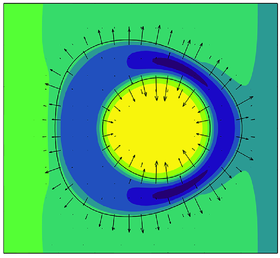
To better appreciate the reason behind the FCD deformation under the impact of a UEMF, figure 13 displays the magnetic force vectors exerted on the FCD along with the pressure field inside the microchannel, in which
 $p^*={p}/({\rho c_s^2 })$
is the normalised pressure. The results are presented at
 $t^* = 2.45$
and
 ${Bo}_m = 2$
for two different values of the magnetic field angles by supposing either the core or shell is ferrofluid. When the core is ferrofluid, it is observed that the magnetic force is not imposed on the outer droplet. Moreover, independent of
 $\alpha$
, a relatively great pressure applied to the shell’s rear side, generates a flat shape. Additionally, at
 $\alpha =0^\circ$
, the inner droplet’s horizontal elongation increases the pressure inside the shell, causing its frontal side to stretch horizontally, as delineated earlier. At
 $\alpha =90^\circ$
, the inner droplet’s vertical stretch compresses the fluid in the upper and lower sides of the shell, making it elongate vertically. In contrast, when the shell is ferrofluid, the magnetic force is applied on both interfaces, whose direction is from the ferrofluid to the non-ferrofluid region. Identical to the former case, high pressure on the rear side of the shell results in a flat shape such that at
 $\alpha =90^\circ$
, the outer droplet approaches a triangular configuration. Also, the pressure inside the inner droplet is noticeably higher than that inside the shell, which is allegedly due to magnetic force direction, pulling the core inward and augmenting the pressure accordingly.
Normalised pressure field inside the microchannel and magnetic force vectors applied to an FCD during its migration at
 $t^* = 2.45$
and
 ${Bo}_m = 2$
for different magnetic field angles when either the core or shell is ferrofluid.

To put it succinctly, meticulously interpreting the magnetic Bond number impacts, the results yielded in this section proved that taking the shell as ferrofluid and exploiting a UEMF along
 $\alpha =0^\circ$
can outstandingly retard the breakup of an FCD moving in a fluid flow. Hence, in the rest of the paper, the shell is assumed to be ferrofluid and the magnetic field is brought to bear at
 $\alpha =0^\circ$
to investigate the effects of other overriding parameters.
3.2. Impact of the capillary number
The capillary number plays a pivotal role in compound droplet deformation. Microfluidic devices regularly perform in a restricted range of
 ${Ca}$
. Therefore, in this research, by varying the flow velocity, the capillary number is altered between 0.05 and 0.30 so that the results are applicable to the pragmatic microfluidic systems. Figure 14 represents
 $T_o$
and
 $T_i$
as a function of time for three distinct values of the capillary number at
 ${Bo}_m = 1$
and
 $\alpha =0^\circ$
when the shell is ferrofluid. Figure 15 exhibits the snapshots of a compound droplet over the course of the movement in the microchannel.
Influence of
 ${Ca}$
on the FCD deformation and breakup over the course of traversing in a microchannel at
 ${Bo}_m = 1$
: (a) variation of the shell deformation with respect to the dimensionless time; (b) variation of the inner droplet deformation with dimensionless time; and (c)
 $L_b^*$
,
 $t_b^*$
and
 $y_b^*$
as a function of the capillary number. The shell is supposed to be ferrofluid and
 $\alpha =0^\circ$
.

Migration of an FCD inside a microchannel from the initial point to the outlet over time for three different capillary numbers at
 ${Bo}_m =1$
and
 $\alpha =0^\circ$
when the outer droplet is ferrofluid. From left to right:
 $t^* = 0, \ 1.36, \ 2.72, \ 4.08, \ 5.44, \ 6.8$
and
 $ \ 8.16$
.

At low capillary numbers (e.g.
 ${Ca} = 0.05$
), the viscous force is inconsequential though the interfacial tension force is notable, which tends to keep the shell in a spherical shape. However, as it was proven in § 3.1, the magnetic force stretches the rear and frontal sides of the shell concurrently. Consequently, as the viscous force is attenuated, the shell procures an ellipsoid configuration owing to the predominance of the magnetic and interfacial tension forces, which is also evident in figure 15 at
 ${Ca} = 0.05$
. Furthermore, as shown in figure 14(a), a smaller
 ${Ca}$
number results in greater horizontal deformation of the shell, and consequently, a higher
 $T_o$
value. By contrast, at the higher values of
 ${Ca}$
, the interfacial tension force is undermined, while the viscous force is accentuated, which flattens the shell’s rear side as described previously. Therefore, at
 ${Ca} = 0.30$
, in which the viscous force is conspicuous, a triangular-like shape is attained (see figure 15). Accordingly, the horizontal elongation of the shell’s rear side, which results from the magnetic force, is suppressed by the viscous force, which in turn reduces the shell deformation, as clear in figure 14(a). Given the inner droplet (figure 14
b), decreasing
 ${Ca}$
attenuates the viscous force that competes with magnetic force. Thus, applied horizontally, the magnetic force deforms the inner droplet more straightforwardly, justifying the appreciable deformation of the inner droplet at
 ${Ca} = 0.05$
when
 $t^* \lt 1.5$
. However, at
 $t^* \gt 1.5$
, for the larger values of
 ${Ca}$
, the viscous force prevails over the magnetic force and eventually deforms the inner droplet into the prolate-like shape.
According to figure 14(c), which plots
 $y_b^*$
,
 $t_b^*$
and
 $L_b^*$
as a function of
 ${Ca}$
, varying
 ${Ca}$
, caused by flow velocity changes, slightly affects dimensionless rupture length and non-dimensional rupture time. Quantitatively speaking, by changing
 ${Ca}$
from 0.05 to 0.30,
 $t_b^*$
increases by merely 5.5 %, equivalent to a negligible delay in the rupture process. In view of the vertical elongation of the inner droplet with the
 ${Ca}$
increment, it is expected
 $y_b^*$
grows, which is also axiomatic in figure 14(c).
3.3. Impact of the density ratio
This section assesses the effect of the density ratio (
 $\rho _r$
) on the FCD breakup occurrence by altering the shell density while keeping the density of the inner drop and the ambient fluid constant and equal. Five different values of the shell density are considered, corresponding to
 $1\leqslant \rho _r \leqslant 10$
. Figure 16 depicts the temporal evolution of the inner and outer droplets’ deformation in advance of the rupture for various density ratios at
 ${Bo}_m = 4$
and
 $\alpha =0^\circ$
, in which the shell is presumed to be ferrofluid. The transport of the compound droplet in the microchannel over time is revealed in figure 17. Contemplating figures 16 and 17, reducing the shell density trivially affects the outer and inner droplets’ deformation. Additionally, decreasing
 $\rho _r$
expedites the rupture process (see figure 16
c). Quantitatively speaking, changing the density ratio from 1 to 2 results in a 17.1 % decrement in the dimensionless rupture time. Curtailing the density of the outer droplet undermines the viscous drag force the inner droplet experiences (Bijarchi et al. Reference Bijarchi, Yaghoobi, Favakeh and Shafii2022), assisting it in moving inside the shell more promptly. Therefore, the inner droplet touches the interface of the shell more swiftly, making the breakup occur sooner, which is also clear in figure 17. Based on figure 16(c), as the density ratio grows,
 $y_b^*$
declines since lessening the outer droplet density (increasing
 $\rho _r$
) alleviates the viscous drag force exerted on the core, decreasing its vertical elongation, which in turn diminishes the height at which the inner droplet reaches the interface of the shell.
Influence of the density ratio (
 $\rho _r$
) on the FCD deformation and breakup over the course of traversing in a microchannel at
 ${Bo}_m = 4$
: (a) variation of the shell deformation with respect to the dimensionless time; (b) variation of the inner droplet deformation with dimensionless time; and (c)
 $L_b^*$
,
 $t_b^*$
and
 $y_b^*$
as a function of the density ratio. The shell is supposed to be ferrofluid and
 $\alpha =0^\circ$
.

Migration of an FCD inside a microchannel from the initial point to the outlet over time for three different density ratios at
 ${Bo}_m = 4$
and
 $\alpha =0^\circ$
when the outer droplet is ferrofluid. From left to right:
 $t^* = 0, \ 1.22, \ 2.86, \ 4.49, \ 6.12, \ 7.75, \ 9.39$
and
 $ \ 11.02$
.

Influence of the viscosity ratio (
 $\nu _r$
) on the FCD deformation and breakup over the course of traversing in a microchannel at
 ${Bo}_m = 1$
: (a) variation of the shell deformation with respect to the dimensionless time; (b) variation of the inner droplet deformation with dimensionless time; and (c)
 $L_b^*$
,
 $t_b^*$
and
 $y_b^*$
as a function of the viscosity ratio. The shell is supposed to be ferrofluid and
 $\alpha =0^\circ$
.

3.4. Impact of the viscosity ratio
Changing the shell viscosity while maintaining the viscosity of the inner droplet and ambient fluid constant and equal, this section scrutinises the viscosity ratio (
 $\nu _r$
) effects. Five distinct values of the shell viscosity are picked out, equivalent to
 $1 \leqslant \nu _r \leqslant 10$
. Hence, the ternary system operates as an O/W/O configuration. Figures 18 and 19 show the time variation of the FCD deformation and the snapshots of the FCD transport inside the microchannel for different viscosity ratios at
 ${Bo}_m = 1$
and
 $\alpha =0^\circ$
, in which the shell is assumed to be ferrofluid. Higher viscosity causes the shell to behave more like a solid, resulting in less deformation. This explains the reduction in outer droplet deformation as the viscosity ratio decreases (see figures 18
a and 19). Interestingly, the influence of the viscosity ratio on the compound droplet deformation under a UEMF is similar to that in the absence of the magnetic field, which is reported by Vu et al. (Reference Vu, Vu and Bui2019a
) and Liu et al. (Reference Liu, Lu, Li, Yu and Sahu2021). Moreover, by augmenting the viscosity ratio (reducing the shell viscosity), the magnetic force may deform the inner droplet more simply when
 $t^* \lt 1.22$
, causing it to be more deformed horizontally (see figures 18
b and 19). Conversely, by lowering the viscosity ratio, in the wake of the higher viscous drag force, the inner droplet ends up conspicuously deforming vertically at the rupture moment. Given figure 18(c), raising the viscosity ratio precipitates the breakup process. To put it differently, for the lowest value of the viscosity ratio (
 $\nu _r=1$
), the FCD can further transport in the microchannel prior to encountering the rupture. Indeed, boosting the shell viscosity (decreasing the viscosity ratio) raises the force the inner droplet requires to move forwards and contact the shell interface, which retards the breakup. Last but not least, regarding figure 18(c),
 $y_b^*$
is not altered by the viscosity ratio.
3.5. Impact of the radius ratio
Preserving the outer droplet radius at 35 lattice units and altering the inner droplet radius, this section is allotted to surveying the influence of the radius ratio (
 $r_r$
). The considered radii for the inner droplet in lattice units are 15, 20 and 25, which correspond to
 $r_r=2.3$
,
 $r_r=1.75$
and
 $r_r=1.4$
, respectively. The changes in inner and outer droplets’ deformation with dimensionless time before the rupture for three distinct radius ratios are depicted in figure 20 at
 ${Bo}_m = 2$
and
 $\alpha =0^\circ$
when the shell is ferrofluid. Also, figure 21 provides the traversing process of the FCD. The shell space is confined as the radius ratio declines. Accordingly, by a finite deformation, the inner droplet touches the shell interface, provoking the breakup. In other words, reducing the radius ratio dramatically accelerates the breakup process, which is consistent with figures 20 and 21. The swift rupture prompted by the inner droplet’s sizeable radius (low radius ratio) prevents the outer droplet from being exposed to the magnetic and drag forces for a sufficient time prior to the rupture, exceedingly limiting its deformation, which is obvious in figure 20(a). Intriguingly, when
 $t^* \lt 1.0$
,
 $T_o$
does not rely on the radius ratio and solely depends on time. According to figure 20(b), by increasing the core radius (curtailing the radius ratio), the inner droplet undergoes a more substantial horizontal deformation when
 $t^* \lt 1.5$
. That is because enlarging the core size impedes the flow development inside the shell (Che et al. Reference Che, Yap and Wang2018), diminishing the velocity magnitude in the shell, which alleviates the drag force applied to the inner droplet. Thus, the magnetic force can further deform the core horizontally. Additionally, the decrement in the drag force allows the core to transport inside the shell more promptly, markedly precipitating the rupture process (see figure 20
c). To exemplify, decreasing the radius ratio from 2.3 to 1.75 accelerates the rupture incidence by 23.9 %. Distinctly, a decrement in the inner droplet size (raising
 $r_r$
) lessens
 $y_b^*$
.
3.6. Impact of the surface tension coefficients
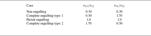
Surface tension between the involved phases critically impacts the FCD morphology. To explore the effects of surface tension coefficients, disparate cases are considered using the stability diagram provided by Guzowski et al. (Reference Guzowski, Korczyk, Jakiela and Garstecki2012), where the feasible equilibrium topologies of two immiscible droplets immersed in a third fluid are proposed. The examined topologies are defined as follows:
-
(i)
 $\left |{\sigma _{13}}/{\sigma _{12}}-{\sigma _{23}}/{\sigma _{12}}\right |\lt 1$
and
${\sigma _{13}}/{\sigma _{12}}+{\sigma _{23}}/{\sigma _{12}}\gt 1$
, where the droplets of the first and second phases bear a common interface and are subjected to the third phase, which is called partial engulfing;
-
(ii)
${\sigma _{13}}/{\sigma _{12}}+ {\sigma _{23}}/{\sigma _{12}}\lt 1$
, where a pair of simple droplets remains separated (Qu & Wang Reference Qu and Wang2012), which is called non-engulfing; -
(iii)
${\sigma _{13}}/{\sigma _{12}}\gt {\sigma _{23}}/{\sigma _{12}}+1$
, where the first phase is engulfed utterly by the droplet of the second phase, which is called complete engulfing-type 1, under which the core is kept inside the shell for a noticeable time; -
(iv)
${\sigma _{23}}/{\sigma _{12}}\gt {\sigma _{13}}/{\sigma _{12}}+1$
, where the second phase is engulfed utterly by the droplet of the first phase, which is called complete engulfing-type 2.


Table 2 summarises the ratio of surface tension coefficients for the various cases discussed earlier. It should be expressed that
 $\sigma _{23}$
is kept constant in all examined cases so that the capillary number is not changed (see (2.37)).
Surface tension ratios of various equilibrium topologies considered in this research.

Migration of an FCD inside a microchannel from the initial point to the outlet over time for three different viscosity ratios at
 ${Bo}_m = 1$
and
 $\alpha =0^\circ$
when the outer droplet is ferrofluid. From left to right:
 $t^* = 0, \ 1.22, \ 2.86, \ 4.49, \ 6.12$
and
 $\ 7.75$
.

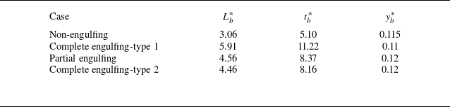
Figure 22 illustrates the time evolution of the deformation of the outer and inner droplets prior to the breakup for different surface tension coefficients at
 ${Bo}_m = 4$
and
 $\alpha =0^\circ$
when the shell is treated as ferrofluid. Interestingly, the core deformation has a direct relation with the
 $\sigma _{23}/\sigma _{12}$
ratio, while the outer droplet deformation has an inverse relation with this parameter. Since
 $\sigma _{23}$
remains constant,
 $T_o$
and
 $T_i$
actually vary with the surface tension coefficient between the inner and outer droplet (
 $\sigma _{12}$
). Thus, though boosting the shell deformation, increasing
 $\sigma _{12}$
diminishes the inner droplet deformation. That is expected as the interfacial tension force impedes the core deformation. This elucidation concurs with figure 22, in which the non-engulfing case bearing the lowest amount of
 $\sigma _{23}/\sigma _{12}$
instigates large deformation of the outer droplet while hindering the significant deformation of the inner droplet. By contrast, bearing the highest value of
 $\sigma _{23}/\sigma _{12}$
, the complete engulfing-type 2 case suppresses outer droplet deformation though causing a remarkable deformation of the inner droplet. This occurrence is clear-cut in figure 23 as well where the transport process of the FCD is shown for several surface tension coefficients. It should be mentioned that in advance of the rupture, inasmuch as the inner droplet and ambient fluid are not in direct contact,
 $T_i$
does not rely on
 $\sigma _{13}$
. However,
 $\sigma _{13}$
plays a crucial role after the breakup as the inner droplet is exposed to the ambient fluid. Concerning figure 23, in the case of non-engulfing, rupture occurs expeditiously since the frontal side of the shell does not maintain the spherical shape and becomes narrower gradually. Therefore, a nose-like structure is eventually created, which restricts the region between the inner and outer droplets, provoking the breakup in a short time (
 $t_b^*=5.10$
). Conversely, the complete engulfing-type 1 condition noticeably delays the rupture incidence as predicted. Dimensionless rupture time (
 $t_b^*$
), dimensionless rupture length (
 $L_b^*$
) and non-dimensional rupture height with respect to the channel centre line (
 $y_b^*$
) are listed in table 3. Contemplating table 3, one may realise that by altering the surface tension coefficient so that the complete engulfing-type 1 condition is procured,
 $t_b^*$
and
 $L_b^*$
grows by 34.2 % and 29.6 %, respectively, compared with the case at which all surface tension coefficients are equal (partial engulfing), which is equivalent to a sharp delay in the breakup. However, surface tension coefficients inconsequentially affect
 $y_b^*$
.
 $L_b^*$
,
 $t_b^*$
and
 $y_b^*$
for various equilibrium topologies considered in this research at
 ${Bo}_m = 4$
and
 $\alpha =0^\circ$
. The shell is presumed to be ferrofluid.

Influence of the radius ratio (
 $r_r$
) on the FCD deformation and breakup over the course of traversing in a microchannel at
 ${Bo}_m = 2$
: (a) variation of the shell deformation with respect to the dimensionless time; (b) variation of the inner droplet deformation with dimensionless time; and (c)
 $L_b^*$
,
 $t_b^*$
and
 $y_b^*$
as a function of the radius ratio. The shell is supposed to be ferrofluid and
 $\alpha =0^\circ$
.

Migration of an FCD inside a microchannel from the initial point to the outlet over time for three different radius ratios at
 ${Bo}_m = 2$
and
 $\alpha =0^\circ$
when the outer droplet is ferrofluid. From left to right:
 $t^* = 0, \ 1.22, \ 2.45, \ 3.67, \ 4.9, \ 6.12, \ 7.35, \ 8.57, \ 9.79$
and
 $\ 11.02$
.

Influence of the surface tension coefficients on the FCD deformation and breakup over the course of traversing in a microchannel at
 ${Bo}_m = 4$
: (a) variation of the shell deformation with respect to the dimensionless time; (b) variation of the inner droplet deformation with dimensionless time. The shell is supposed to be ferrofluid and
 $\alpha =0^\circ$
.

Migration of a ferrofluidic compound droplet inside a microchannel from the initial point to the outlet over time for disparate surface tension coefficients at
 ${Bo}_m = 4$
and
 $\alpha =0^\circ$
when the outer droplet is ferrofluid. From left to right:
 $t^* = 0, \ 1.22, \ 2.86, \ 4.49, \ 6.12, \ 7.75, \ 9.39$
and
 $ \ 11.02$
.

3.7. Regime diagrams of the deformation and breakup
In this section, the morphology of the FCD is analysed thoroughly when the shell is ferrofluid and the UEMF is applied along
 $\alpha =0^\circ$
, the circumstance under which the onset of the breakup is strikingly postponed (see § 3.1). By varying
 ${Bo}_m$
and
 ${Ca}$
, five distinguished regimes were observed: semi-spherical, triangular-like, egg-like-type 1, egg-like-type 2 and tadpole-like, all of which are discussed here.
Figure 24 displays a typical example of the observed regimes. Depicted in figure 24(a), the semi-spherical regime happens at the small values of magnetic Bond (
 ${Bo}_m \leqslant 2$
) and capillary (
 ${Ca} \leqslant 0.15$
) numbers. In light of the gentle magnetic force, the outer droplet elongation is small (e.g. for the shown case,
 $T_o=0.047$
at the rupture moment). Moreover, due to the small
 ${Ca}$
, the interfacial tension force is significant, which prevents the shell from deviating from the spherical configuration. Accordingly, the shell’s configuration roughly resembles a spherical shape. The meagre elongation of the shell’s frontal side originates from the magnetic force. In this regime, the inner droplet stretches vertically at the rupture instant, which corresponds to
 $T_i\gt 0$
.
Figure 24(b) represents the triangular-like regime, taking place when
 ${Bo}_m \leqslant 4$
and
 ${Ca} \geqslant 0.15$
. In this regime, the viscous drag force is intensified due to the higher values of
 ${Ca}$
, which flattens the rear side of the shell. Similar to the previous regime, as the magnetic force is inconsequential, the horizontal elongation of the shell is restricted. Consequently, the shell eventually reaches the triangular configuration. Furthermore, in this regime, the inner droplet generally stretches along the
 $y$
-axis.
Revealed in figure 24(c), the egg-like-type 1 regime is observed merely three times for the lowest studied
 ${Ca}$
(0.05) and
 $2 \leqslant {Bo}_m \leqslant 4$
. By virtue of the low
 ${Ca}$
, the interfacial tension force strives to maintain the outer droplet in a spherical configuration. However, the magnetic force elongates both sides of the shell, implying that the shell approaches an ellipsoid shape. Moreover, since the viscous force is negligible relative to the interfacial tension force, the vertical elongation of the inner droplet is suppressed. Hence, intriguingly, the inner droplet does not touch the shell at the upper and lower sides at the breakup moment; instead, solely, the tip of the inner droplet contacts the shell, ending up with an egg-like configuration. In this regime,
 $T_o$
and
 $T_i$
are negative, referring to the horizontal elongation.
A typical example of the distinct regimes occurring during the movement of an FCD in a microchannel in the simultaneous presence of the pressure-driven flow and a UEMF. The shell is presumed to be ferrofluid and the UEMF is applied along
 $\alpha =0^\circ$
: (a) semi-spherical regime (
 ${Bo}_m = 0$
,
 ${Ca} = 0.05$
); (b) triangular-like regime (
 ${Bo}_m = 1$
,
 ${Ca} = 0.25$
); (c) egg-like-type 1 regime (
 ${Bo}_m = 2$
,
 ${Ca} = 0.05$
); (d) egg-like-type 2 regime (
 ${Bo}_m = 4$
,
 ${Ca} = 0.20$
); and (e) tadpole-like regime (
 ${Bo}_m = 7$
,
 ${Ca} = 0.25$
).

Figure 24(d) exemplifies the egg-like-type 2 regime, taking place at the moderate
 ${Bo}_m$
(
 $3 \leqslant {Bo}_m \leqslant 5$
) for
 ${Ca} \geqslant 0.10$
. The morphology of inner and outer droplets resembles the previous regime; by contrast, in this regime, as
 ${Ca}$
grows, the viscous force instigates the vertical elongation of the inner droplet, causing it to touch the shell at the upper and lower sides instead of a point.
By further augmenting
 ${Bo}_m$
, the tadpole-like regime arises, as demonstrated in figure 24(e). Observed at high magnetic Bond numbers, the tadpole-like regime embraces the notable horizontal elongation of the shell induced by the magnetic force. Actually, the shell’s rear side becomes longer and narrower, ending up approaching a tail-like structure. However, the frontal side of the shell’s interface remains wider at the breakup moment. Among the five distinguished regimes, the core and shell’s deformation is the greatest in the tadpole-like regime. Identical to the previous regime, the core touches the outer droplet at the lower and upper sides when the breakup occurs.
The regime map of the FCD traversing in the microchannel is given in figure 25 for a wide range of
 ${Bo}_m$
(0–8) and several
 ${Ca}$
ranging from 0.05 to 0.30. The semi-spherical regime is restricted to the region where magnetic and viscous forces are small compared with the interfacial tension force so that the FCD structure does not deviate remarkably from its initial spherical shape. The triangular-like regime emerges when
 ${Ca} \leqslant 0.30$
and
 ${Bo}_m \leqslant 4$
. As
 ${Bo}_m$
rises, one should boost
 ${Ca}$
so that this regime happens. That is because the viscous force should be so considerable that it can compete with the magnetic force and deform the shell’s rear side into a flat shape. As discussed earlier, the egg-like-type 1 regime only arises for the lowest
 ${Ca}$
surveyed and low to moderate
 ${Bo}_m$
. By augmenting
 ${Ca}$
, the transition from the egg-like-type 1 regime to the egg-like-type 2 regime takes place. Ultimately, as
 ${Bo}_m$
increases, the tadpole-like regime is observed, whose characteristics were delineated previously.
Regime map of an FCD moving in a microchannel under the concurrent effects of the pressure-driven flow and a UEMF in
 ${Bo}_m {-} {Ca}$
parameters. The shell is presumed to be ferrofluid, and the UEMF is applied along
 $\alpha =0^\circ$
. The demarcation lines are for illustrative purposes.

Eventually, figure 26 illustrates the variations of the dimensionless breakup length of FCD (
 $L_b^*$
) versus
 ${Ca}$
and
 ${Bo}_m$
when the shell is ferrofluid and
 $\alpha =0^\circ$
, in which each colour corresponds to a specific regime. This diagram unveils how altering
 ${Ca}$
and
 ${Bo}_m$
may result in a dramatic increase in breakup length, which alludes to a delay in the rupture incidence. To be pragmatic in a circumstance where one requires to retard the breakup until
 $x/H = 4$
, in figure 26,
 $L_b^*\lt 4$
is represented by rectangular cuboids, while
 $L_b^* \geqslant 4$
is indicated by cylinders. For
 ${Bo}_m \lt 3$
, altering the capillary number trivially raises the breakup length. Furthermore, when
 ${Ca}$
is low, augmenting
 ${Bo}_m$
insignificantly raises the dimensionless breakup length. However, as
 ${Ca}$
grows, the impact of the magnetic Bond number on retarding of the rupture process becomes more pronounced. Quantitatively speaking, when
 ${Ca} = 0.20$
, augmenting the magnetic Bond number from 1 to 2 results in a 12.0 % increment in the breakup length. Moreover, interestingly, in the case of the semi-spherical, triangular-like and egg-like-type 1 regimes, the dimensionless rupture length is below 4 for all values of
 ${Ca}$
and
 ${Bo}_m$
, alluding to a prompt rupture. Conversely, for the egg-like-type 2 regime, the rupture length is higher than 4, independent of the
 ${Bo}_m$
and
 ${Ca}$
values. Also, concerning the tadpole-like regime, except for two cases where
 ${Ca} = 0.05$
and
 ${Bo}_m \lt 7$
, the dimensionless rupture length is greater than 4. Consequently, to increase the breakup length until
 $x/H = 4$
for a genuine application, one should select the
 ${Bo}_m$
and
 ${Ca}$
such that the egg-like-type 2 and tadpole-like regimes are obtained.
Dimensionless breakup length (
 $L_b^*$
) with respect to
 ${Ca}$
and
 ${Bo}_m$
for five distinct regimes observed during the traversing of an FCD in a microchannel under the impacts of the pressure-driven flow and UEMF. The shell is supposed to be ferrofluid and
 $\alpha =0^\circ$
. Cylinders represent
 $L_b^* \geqslant 4$
, whereas rectangular cuboids demonstrate
 $L_b^*\lt 4$
.

4. Conclusion
For the first time, the hydrodynamics and morphology of a single-core ferrofluid compound droplet (FCD) migrating in a channel flow under a uniform external magnetic field (UEMF) were scrutinised exhaustively. The chief objective of this study is to determine the dominant parameters such that the breakup phenomenon is retarded. The finite-difference method was coupled with the two-dimensional (2-D) multiple-relaxation time lattice Boltzmann approach to systematically assess the ternary fluid system and magnetic field. The influences of (1) magnetic Bond number (
 ${Bo}_m$
), (2) capillary number (
 ${Ca}$
), (3) density ratio, (4) viscosity ratio, (5) radius ratio and (6) surface tension coefficients were investigated on (1) outer droplet deformation (
 $T_o$
), (2) inner droplet deformation (
 $T_i$
), (3) dimensionless breakup time (
 $t_b^*$
), (4) dimensionless breakup length (
 $L_b^*$
) and (5) the breakup height with respect to the channel centreline (
 $y_b^*$
) by presuming either the inner droplet (core) or the outer droplet (shell) is ferrofluid when the UEMF is enforced along
 $\alpha =0^\circ$
and
 $\alpha =90^\circ$
relative to the fluid flow. Succinctly, the following overriding conclusions may be drawn.
-
(i) Regardless of the magnetic field angle, when taken as ferrofluid, the inner droplet undergoes a considerable deformation, while the shell deformation is restricted, gradually confining the region between the core and shell and resulting in a swift breakup. Moreover, as the core is supposed to be ferrofluid, the magnetic force is not brought to bear on the shell. However, interestingly,
$T_o$
increases with
${Bo}_m$
since the magnetic force elongates the core horizontally, which in turn compresses the fluid inside the shell, boosting the shell deformation. -
(ii) Selecting the shell as ferrofluid and imposing the UEMF at
$\alpha =90^\circ$
dramatically precipitates the rupture. Conversely, when applied at
$\alpha =0^\circ$
, the magnetic field may retard the breakup process. Hence, the rest of the simulations were conducted at
$\alpha =0^\circ$
by supposing the shell to be ferrofluid. -
(iii) When the shell is ferrofluid, the pressure inside the core is augmented, possibly by virtue of the magnetic force direction pulling the core inward.
-
(iv) Curtailing
${Ca}$
accentuates the interfacial tension force striving to hold the compound droplet in a spherical configuration. Thus, when
${Ca}$
is low, applying a UEMF brings about an ellipsoid configuration as the magnetic force stretches the frontal and rear sides of the shell simultaneously. In contrast, as
${Ca}$
increases, the viscous force flattens the shell’s rear side. Under this condition, enforcing a gentle magnetic force generates a triangular-like shell. -
(v) Though expediting the rupture process, increasing the density ratio (reducing the shell density) negligibly affects
$T_i$
and
$T_o$
. -
(vi) Raising the viscosity ratio undermines the drag force applied to the core. Accordingly, the core can transport inside the shell more promptly, accelerating the breakup.
-
(vii) As the core radius is reduced, the region between the core and shell increases, allowing the flow development inside the shell, which in turn enlarges the velocity magnitude in the shell. The velocity increment intensifies the drag force applied to the inner droplet, slowing down its movement and drastically retarding the rupture.
-
(viii) While reducing the inner droplet deformation, increasing the surface tension coefficient between the core and shell augments the shell deformation. Additionally, by altering the surface tension coefficient such that the complete engulfing-type 1 condition is attained, the rupture length grows by 29.6 % compared with a circumstance under which all surface tension coefficients are equal, corresponding to a striking delay in the breakup.
-
(ix) By varying
${Bo}_m$
from 0 to 8 and
${Ca}$
from 0.05 to 0.30, five distinct breakup regimes were observed: (1) semi-spherical; (2) triangular-like; (3) egg-like-type 1; (4) egg-like-type 2; and (5) tadpole-like, whose regime map was constructed in
${Bo}_m {-} {Ca}$
parameters. -
(x) Surveying the FCD breakup length in various regimes, one may ascertain that by changing
${Ca}$
and
${Bo}_m$
so that the egg-like-type 2 and tadpole-like regimes are accomplished, the breakup length increases, which postpones the rupture process accordingly.


Having an immediate application in drug delivery in which retarding the breakup incidence is favourable, the study endeavours to bridge the gap between FCD hydrodynamics and microfluidics. However, the hydrodynamics and morphology of an FCD under the simultaneous influence of the fluid flow and UEMF is a convoluted topic, entailing more thorough investigations to elucidate all the ins and outs of this paramount issue.
Supplementary material
Supplementary material is available at https://doi.org/10.1017/jfm.2025.10226.
Declaration of interests
The authors report no conflict of interest.
Data availability statement
The data that support the findings of this study are available on request from the corresponding author, [M.A.B].